Experimental Validation of the Solid State Substation
with Embedded Energy Storage Concept
Christian Klumpner Mohamed Rashed Dipankar De Chintan Patel Pongorn Kulsangcharoen Greg Asher Department of Electrical and Electronics Engineering
University of Nottingham Nottingham, UK [email protected]
Abstract— This paper proposes the concept of integrating the energy storage within a Medium Voltage to Low Voltage solid state substation in order to provide new features compatible with the requirements from future more intelligent grids. The principles for the system development are presented and the role of each subsystem is explained. The experimental evaluation of the 1.9kVrms/25kVA substation with 1.5MJ of supercapacitor storage consists of subsystem tests showing the waveform quality, step transients as well as system tests of the efficiency, ride-through and power peak shaving operation.
Keywords— DC/DC converter; energy storage; efficiency; interleaved converter; multilevel converter;ride through.
I. INTRODUCTION
Energy storage [1] is considered the solution to multiple problems existent in today’s transmission and distribution of electricity related to the intermittency of renewable power generation, large scale (wind) or small scale (residential PV) or to the typical mismatch that exists between power consumption that follows consumer demand and the traditional power generation that is slow varying to maximize conversion efficiency and financial returns. Various technologies exist
i) pumped hydro [2], a technology already commercially available, suitable for large scale with fast response and high round trip efficiency but requiring significant investments and significant alteration of the natural habitat (mountain);
ii) compressed air which has the capability to provide low capital cost with low environmental impact as compressed air can be stored in underground caverns (medium scale) or under water “Energy Bags” [3] (large scale) but not offering very high conversion efficiency and not having fast response time;
iii) electrochemical storage in batteries or supercapacitors [4] are more expensive, but as the energy is stored/retrieved in electrical form, can result in significantly higher conversion efficiency and very fast response time, which is essential to improve the stability of a power grid, especially for weak grids that may contain also distributed generation.
Most large scale Energy Storage Systems (ESS) rely on electromechanical conversion via an AC electrical machine operating both as generator (discharging) and motor (charging), which means an additional converter is needed to convert hydraulic or pneumatic power to mechanical. Operation with variable speed of the mechanical actuators may be beneficial to
maximize the conversion efficiency when the reference power for the ESS deviates significantly from the rated conditions but this implies the need of an additional AC(variable frequency)/DC/AC(fixed frequency) converter that adds additional cost and losses. For this reason, most medium and large scale ESS will have a very restricted power range capability. In applications where accurate power peak leveling is required, it may not be acceptable to disable the ESS at low power which means a versatile ESS technology is needed. This can work alone or in conjunction with a bulk/large ESS to complement its capability, resulting in a hybrid ESS solution.
Today’s distribution networks face also a challenge related to the need to enable redistribution of renewable energy generated at the point of consumption, to potential consumers which may result in situations where renewable/distributed generation exceeds local consumption, so the excess electrical power travels upstream to new potential consumers. This however, is not fully supported by the technologies involved in today’s substations and it is envisaged that more power electronics will be used to provide additional functionality (reactive power and voltage control, improved power quality by means of active filtering, interphase power balancing etc) whilst the use of medium frequency in the power transformers may enable important size reductions that are essential for supporting future needs for more power to be delivered to consumers in a given footprint of the substation. It is easy to imagine that embedding energy storage within a solid state substation already containing the AC/DC/AC conversion stages may be a straightforward upgrade with a clear set of benefits: - Possibility to store locally the excess generated power/energy
that can be consumed later during peak consumption times; - Possibility to operate the distribution grid in an islanded
mode, completely disconnected from the main grid, in case maintenance work is needed to the MV interconnection or in case of short term grid faults, by implementing grid fault ride through capability within the substation;
- Possibility to delay upgrades in the interconnection lines to accommodate a higher peak power requested by the loads, by implementing peak power shaving at substation level; - Possibility to take advantage of dynamic electricity pricing,
by buying cheap electricity during nigh to cover consumption of electricity during early morning before domestic renewable/PV generation is fully available.
This paper proposes and experimentally evaluates the concept of a substation with embedded energy storage. The project objectives that led to the development of the power converter structure will be first presented followed by the topology and operation of each subsystem. Then the experimental evaluation showing the performance of each subsystem will be shown and last, the performance of the whole system during relevant tests will be discussed.
II. THE TOPOLOGY OF THE SOLID STATE SUBSTATION WITH
INTEGRATED ENERGY STORAGE
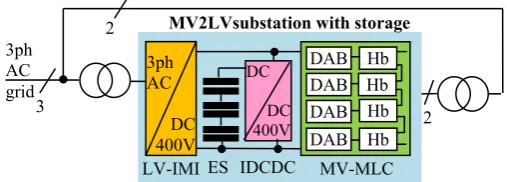
The main objective of the research project reported in this paper was to implement a medium voltage (MV) to low voltage (LV) substation demonstrator with integrated energy storage that involves extensively power electronic technologies and experimentally assess its performance to determine in full the benefits this technology could offer if deployed on large numbers in distribution networks. Since the solutions investigated were aimed at MVA power levels that could support also large amounts of energy storage, a modular solution was considered, consisting of a multilevel inverter front end interfacing with the MV port, with modular DC/DC converters connected to the DC-links of each inverter module, having the ability to provide the galvanic isolation between the different DC-links and to process bidirectional power with a common low-voltage (<1kV) DC-bus where the LV inverter stage connects to the LV distribution network, but also where the modular energy storage stacks with individual DC/DC converters connect in a three-port fashion. The topology of this system is shown in Fig. 1. Due to increased complexity of the system, only a single phase multilevel inverter with the capability to generate 31 voltage levels has been considered. The voltage rating was chosen to match the phase-to-neutral voltage level of a 3.3kVrms MV system which is 1.9kVrms. On
the LV side, a 3-phase modular inverter topology with interleaved channels was considered, which offers important switching ripple reduction and small size of passive components with minimal control effort. A similar interleaved DC/DC converter structure was considered to interface the energy storage (supercapacitor stack) characterized by variable voltage (dependent on the supercapacitors state of charge), to the constant voltage (400V) of the interconnecting DC bus.
Considering the topology of the system shown in Fig. 1, a secondary objective was assumed, to perform a comparative evaluation of the performance of two converter technologies for energy storage systems aimed at being connected to an MV grid. First technology was based on a low-voltage converter technology considered state-of-the-art in medium/high power inverter by the power electronics industry that can be optimized for low cost and minimizes complexity, connected to MV grid via a 50Hz transformer. The second technology was a true MV multilevel converter technology that can be considered state-of-the-art in power electronics research that maximizes performance and functionality. In terms of performance indicators, not only the level of rated/peak round trip efficiency was considered important but also the range of load powers where this efficiency remains constant because highly versatile energy storage systems are supposed to be able to operate in peak power shaving mode where it is expected that for a
[image:2.595.306.560.87.178.2]significantly longer period of time, they will operate at reduced power levels, where efficiency typically degrades significantly.
Fig. 1. The block diagram of the lab demonstrator design and built to demonstrate the concept of solid state substation with embedded storage
A detailed simulation study was carried out initially in order to identify the realistic power converter candidates that can enable the implementation of the solid state substation with embedded storage concept, considering a power rated of 10MVA [5]-[8]. Priority was given to converter topologies that enabled for modularity, and also had their implementation aspects extensively investigated by the research community, resulting in a low implementation risk for the potential system integrator. Simulation models provided results for validating the design specification, the control methods and assessing the stress of components, the harmonic performance and the power losses [5]-[9]. Based on this, a reduced scale demonstrator rated at 25kVA with a 1-phase MV input at 1.9kVrms was
implemented which allowed for a realistic experimental validation to be carried out. Another aspect considered to make the projection of experimental performance realistic was the choice of materials. For power semiconductors, the reasonably priced Infineon Trench/Fieldstop IGBT3 and Emitter Controlled 3 diode devices packed in an Easypack power module were chosen as these offered a good loss vs cost tradeoff. In the design of magnetics, metglass core was considered for the coupled inductors subject to full switching frequency magnetization cycle whist for the medium frequency transformers, ferrite core was used to keep core losses minimum, which is typically achieved in distribution transformers, whist the frequency of operation was kept to a realistic level (5kHz) achievable also at higher power rating with semisoft or resonant operation of the H-bridge inverter in the DAB, but also to allow for a higher efficiency which is an important aspect in energy storage and also distribution substation applications. The stresses in the magnetic core as well as in the winding were kept at reasonable high levels, so that the resulting performance will be realistic for a power electronic system designed in a cost-effective manner.
A. The Cascaded Multilevel Inverter with Asymetric Bridges
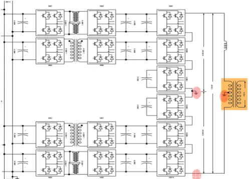
In order to be able to produce a MV waveform with minimum consumption of semiconductors but high quality of the waveform, an asymmetric cascaded structure of H-bridge inverters that can generate 31-voltage levels shown in Fig. 2, was adopted. To minimise the design effort, only two designs for the H-bridges were considered: a high voltage (operating at 800V in the dc-link) and a low voltage (operating at 400V and below in DC-link) that was extensively used in the other subsystems.
3ph AC
DC 400V 3
2
2 3ph
AC grid
MV2LVsubstation with storage
LV-IMI
DC
DC 400V
MV-MLC DAB DAB DAB DAB
Fig. 2. The topology of a 31-level multilevel converter with asymmetric H-bridges fed from a low voltage DC-bus via modular Dual Active Bridge DC/DC converters using medium frequency transformers to provide isolation. Note: only one grounding point in the MV circuit can be used at any time.
To minimize the potential voltage stresses on the isolation, the string structure was built in a mirrored arrangement, with the lowest voltage rated bridges located in the middle and the highest voltage rated at the edges. This gave the possibility for the midpoint of the string to be grounded for safety reasons, which kept the voltage potential at each end of the string terminal just under 1kVrms even though the full leg would
produce 1.9kVrms (the rated phase voltage of a 3.3kV MV
[image:3.595.39.289.58.237.2]grid). In a 3-phase MV-MLC, the lower terminal of the string which is shared with the other phase strings will be grounded.
Fig. 3. The cabinet containing the MV cascaded multilevel converter and the associated dual active bridge (DAB) DC/DC converters as represented in Fig.2. Cabinet size: W=1600, H=2000, D=500mm.
The MLC uses a combination of resonant controllers to mitigate the influence of harmonics and a combination of repetitive+resonant controllers in the Park-PLL block to decouple any negative effects of disturbances contained in the supply voltage, as illustrated in Fig. 3. The full implementation and validation of the control are found in [9].
θ
-j
e θ
j e
θ
-j
e ejθ
PI
α u
* dq
i idq^
^ Ldq
i
~ Ldq
i ^
Ldq
i
θ
-j e θ
j
e
1 + s τ
1
1 + s τ
1
^ q
U u
Fig. 4. a) The control scheme for the single phase multilevel converter (MLC) and b) the Park-PLL scheme with RPC based filters
The waveform quality of the MV multilevel inverter operating in steady state is shown in Fig.5a for rectifier (Pac = 20.3kW; Pdc= 18.6kW) and Fig 5b for inverter mode (Pdc = 22.67kW; Pac= 21.9kW), with the difference (1.7kW) accounting for the MLC losses. The typical multilevel voltage profile that follows a sinusoidal shape with small PWM ripple (fsw=5kHz) is clearly visible in both situation and the result of
[image:3.595.307.564.376.492.2]this high quality PWM waveform is a very high quality current.
Fig. 5. Steady state performance of the MLC in both rectifier mode (left) and inverter mode (right)
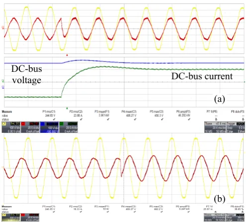
Fig. 6 shows the MV side AC voltage and current and the DC-bus voltage and current during an inverter to rectifier power reversal. The DC voltage/active power control seems to reach quasi steady state in ≈60ms whilst the initial power swap takes place within few ms. The 100Hz ripple seen in the DC-bus current and power is the result of the having a single phase inverter with limited smoothing embedded in the cascaded H-bridges and a stiff voltage control implemented in DABs [11].This ripple cannot be contained within the DAB decoupling capacitors because the DC-bus that interconnects the three subsystems is low inductance and the ripple is shared by all capacitors connected to the DC bus from all three subsystems.
Fig. 7 shows a reactive power step change from leading to lagging which happens instantly. A very small distortion of the waveforms is visible after the step due to the repetitive nature of the controller that needs 1-2 periods to settle.
DAB input HF trafo
4xHF trafo DAB
HV DAB
LV DAB
HV HB HF trafo
LV HB LV HB float
[image:3.595.40.284.418.602.2]Fig. 6. The transient performance is also evaluated in active power reversal tests performed at 17.5kW AC side power.
Fig. 7. Full capacitive to inductive reactive power step transient
[image:4.595.38.289.283.433.2]B. The Supercapacitor Interleaved DC/DC Converter
Fig. 8a shows the topology of the 8 channel interleaved buck-boost DC/DC converter with coupled inductors arranged in three stages that is used to interface the variable voltage supercapacitor stack (384V/200A) able to deliver 75kW peak power to the 400V constant DC bus. The DC-DC converter uses the same design as the LV-H-bridge used in MV-MLC. The design of the magnetics and the control has been detailed in [10]. The cabinet where the actual supercapacitor subsystem was integrated is shown in Fig.8b. The subsystem consists of eight series connected 165F/48V Maxwell boostcap modules.
The typical response to a constant power charge/discharge cycle of the interleaved DC/DC converter is shown in Fig. 9. By sampling the state variables at 40kHz, it is possible to achieve a current response time of less than 0.15ms as shown in Fig. 9b. The other advantage of employing the interleaved technique is that even though the inductors are designed for a relatively high ripple of the channel currents to minimize their size, the overall ripple will be significantly reduced by harmonic cancelation as the waveform of the cumulated supercapacitor current proves, having an insignificant level of ripple of a much higher frequency.
Fig. 8. a) 8-channel interleaved buck-boost DC/DC converter with multistage coupled inductors for interfacing a supercapacitor stack to the constant DC-bus; b) the prototype implementation of the 20F/384V supercapacitor based energy storage system. Cabinet size: H=2000mm; W=1200mm; D=500mm.
Fig. 9. Experimental validation of the supercapacitor converter subsystem whilst performing a) 17.5kW constant power cycling (20s/div) and b) zoom in (0.2ms/div) the power reversal. Switching frequency is 10 kHz/ch; Supercapacitor current ripple is 80kHz.
(b) (a)
Channel current (10A/div)
Cumulated supercapacitor current (50A/div) Ch 1 current (10A/div)
Ch1+2 current (20A/div) Supercapacitor (Ch 1-8)
current (80A/div)
Supercapacitor stack Voltage (50V/div)
(b) (a)
MV Converter Voltage (1kV/div)
MV Converter Grid Current (10A/div)
DC-Bus Voltage [100V/div]
DC-Bus Current (20A/div) in dark green
[image:4.595.307.559.415.674.2]This allows for the reduction of the size of magnetic core used in the inductors designed to limit the circulating current. Since magnetic components have the poorer specific energy (J/kg) this technique enables a significant reduction in the weight of the equipment and also cost as the core (metglas) needs to be high quality as is subject to high frequency full magnetization cycle. Another interesting property of this arrangement is that the size of the magnetic core for each of the 3 stages remains the same, leading to larger numbers of the same magnetic core component resulting in lower unit price.
C. The Low Voltage Interleaved Modular Inverter (LV-IMI)
The topology of the LV-IMI is shown in Fig. 10. It consists of multiple H-bridge inverters of an identical design as the LV-HB used in the MLC subsystem. Each H-bridge uses interleaving of the gating signals for the two legs and has its outputs interconnected via a coupled inductor in order to achieve the highest degree of switching ripple cancelation. Further cascading in successive stages is possible, similar to the Supercapacitor DC/DC converter subsystems but since the output voltage capability of the bridge is smaller, it was chosen to interconnect this subsystem to the grid via two 50Hz transformers that allowed the investigation of the secondary objective, the evaluation of the performance of a MV ESS that uses LV inverters and a step up 50Hz transformer. It can be seen that this design is highly modular, resulting in a dual structure which may prove advantageous in cases where redundancy is required or to improve the efficiency at reduced processed power by completely disabling one of the units and removing the associated stand-by (core) losses with the operation of the transformer at no load.
[image:5.595.307.568.52.209.2]Fig. 10.The topology of the LV Interleaved Modular Inverter (LV-IMI). Note: the transformers depicted have been used to provide added functionality in assessing the performance of an LV system to be potentially connected to an MV system via a 50Hz step up transformer.
[image:5.595.37.286.403.577.2]Fig. 11 shows how the PWM switching ripple present in the voltage at different stages of the coupled inductor filter is reduced in the LV interleaved modular inverter. It can be noticed that the effect of interleaving in conjunction to the use of coupled inductors leads to multilevel type waveforms.
Fig. 11.Illustrating how the first switching harmonic is reduced in the LV interleaved Inverter: a) pole (phase-to-mid-dc-link) voltage; b) line-to-line cell voltage (3 levels); c) transformer secondary (inter-cell) voltage (5 levels); d) FFT of secondary voltage; e) FFT of line-to-line voltage; f) FFT of differential mode voltage; g) FFT of pole (phase-to- dc-link midpoint) voltage.
Fig. 12a shows the response of the LV-IMI to an inverter to rectifier power steps transient that reveals a response time of 60ms. The control scheme involved in the LV-IMI (not shown) is a standard one that uses PI controllers to control the d and q synchronous reference frame current components and the use of a PLL to extract the angle of the direct sequence of the grid voltages. This works reasonably well with some minor distortion noticed in the currents due to the influence of voltage harmonics present.
Fig. 12b shows the result of performing a step change in the reactive power from full capacitive to full inductive reactive power injection. Since the DC-bus voltage is not disturbed, this transition is only characterized by the bandwidth of the current controller which results in response time of under 1ms.
Fig. 12.Transient performance when a) the active power (17.3kW) is reversed and b) the reactive power changes from 14.7kVAr capacitive to inductive.
(a) (b) (c) (d) (e)
(f) (g)
(a)
(b) DC-bus current DC-bus
[image:5.595.305.553.440.665.2]D. Comparison of the Front End InverterTechnologies
The harmonic performance of both competing power electronic technologies is excellent, as denoted by the waveforms presented. The MV MLC, however, achieves this whilst needing much smaller size of magnetic components because MV/LV isolation is achieved via medium frequency transformers rather than 50Hz and also because the 31-level inverter is having significantly smaller PWM voltage ripple and current rating which leads to significantly smaller size needed for the line side inductance. On the other hand, it should be noted that the LV-Interleaved Modular Inverter operates in fact with a fairly high virtual switching frequency as seen by the magnetics which allowed a further minimisation of the coupled inductors beyond what would be available if the power level of one unit will be increased in the range of hundreds kW as needed in a multi MW system.
The reactive power transient performance of the two active front end technologies is similar, even though it is expected to differ since the line-side inductance that opposes the fast change of the current can be much smaller for the MV-MLC converter than the LV-IMI. The reason why there was no visible difference is that in order to achieve a safe and simple hardware implementation of the MV MLC setup, a step up 50Hz transformer was in fact inserted in the main AC path inherently increasing its input impedance and the associated line-side inductance.
III. EXPERIMENTAL VALIDATION OF THE SOLID STATE
SUBSTATION SYSTEM WITH INTEGRATED ENERGY STORAGE
This stage included assessing the efficiency of the system in substation mode as well as the roundtrip efficiency of the system used in energy storage mode and also the performance when performing grid fault ride through and peak power shaving.
A. Efficiency Evaluation of theSystem
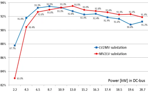
[image:6.595.307.558.53.211.2]The evaluation of the system efficiency is conducted in two conditions shown in Fig. 13 and 14. The efficiency of the system demonstrator operating in MV(1-ph)-to-LV(3-ph) substation mode is shown in Fig. 13 for both directions of power flow. In this case, the associated losses with the transformer connecting the interleaved LV inverters are not included in the overall efficiency calculations as it is considered a transformer will not be needed to connect the LV inverter to an LV distribution grid. It can be seen that a top efficiency of >93% can be achieved in a power range of 20-50% of the rated power level which is where most distribution transformers are operating for most of the time. It should be noted that this efficiency level was achieved even at this relatively low power rating of the demonstrator and using standard components and that implementation at MW power levels with more specialized components (SiC devices) may result in better efficiency.
Fig. 13.Efficiency curves of the solid state substation when the active power flows from the MV side to the LV side (MV2LV) and viceversa (LV2MV). The power flow (x-axis) was measured in the 400V interconnecting dc-bus
If the proposed system is characterized for energy storing applications, it is possible to exchange power with the grid via any of the two inverters. This means it is possible to do a comparative experimentally assessment of the roundtrip efficiency of an energy storage system connected to an MV grid based on each of the two active front end technologies: the low voltage interleaved modular inverter with 50Hz step-up transformer and the true MV inverter which has the galvanic isolation provided by the medium frequency transformers within the DABs. In this case, it is noticed that the losses in the 50Hz step up transformer of the LV-IMI have to be now considered in the calculation of the round trip efficiency. Measurements have been carried out using two separate measurement methods, by setting up the supercapacitor system to perform a series of identical constant power charge/discharge cycles between two predefined voltage limits and measure power and energy flow with a 12-bit oscilloscope (Lecroy) and a Power analyzer (PPA3530 from N4L). Several efficiency points were calculated for each processed power and the average for each power level is displayed in Fig. 14. It can be seen that using averaging reduces significantly the errors which is also denoted by a good convergence of the efficiency levels recorded by the two instruments/methods. It can be noted that the roundtrip efficiency exceeds 86% (these include also losses in the supercaps) for an ESS interfaced via the MV multilevel converter and this is significantly higher than the efficiency of the inverter with 50Hz step-up transformer which was a component procured on a commercial basis based on a most competitive quote (no efficiency target imposed). It can be noted that the efficiency of the LV inverter could be improved by specifying the transformers to have low standby (core) loss, which is achievable by using metglas core but this may then lead to significant increases in the costs. On the other hand, the MV inverter provides a fairly flat efficiency curve (>85%) in a wide range of powers (7.5-20+kW) mainly due to the
Fig. 14.Comparative evaluation of the round trip efficiency of the two Energy Storage Systems based on the MV multilevel converter (MV_MLC) and the LV interleaved converter (LV_interleaved) using two different measurement methods based on a power analyser (PPA) and a 12-bit oscilloscope.
B. Ride through Operation of the Substation System
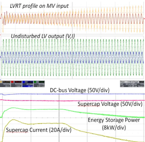
The operation of the substation with embedded energy storage under a grid fault on the MV port is illustrated in Fig. 15. An electronic power supply was used to emulate a voltage drop with an envelope specified by the grid codes. Voltage levels were lower due to the impossibility of the electronic AC power supply to generate 1.9kVrms. The MLC initially operates
with rated active power but once the drop of supply voltage is sensed by the control, the MV converter control switches to full reactive current injection (grid support mode) which is reflected by the grid current maintaining its amplitude but starting to lead the voltage by 90°, which means it can no longer supply active power to the DC-bus/LV inverter. The DC bus voltage experiences a small voltage dip but the benefit of having energy storage capability connected to the DC-bus via a very fast DC/DC converter is seen in Fig.15. This shows that the supercapacitor system which is controlled to provide fast DC-bus voltage control, senses the disturbance in the 400V DC bus system caused by the impossibility of the MV converter to supply the active power required by the LV loads and compensates for the missing power/energy, reflected in the supercapacitor current and power rising sharply. The result is that the LV side inverter continues to operate unaffected throughout the grid fault as reflected by the LV grid voltage and currents, providing full grid fault ride-through functionality as specified in the grid codes. As the grid voltage recovers, once it exceeds 50% of the rated level, the MLC converter is allowed to absorb also active power and this is denoted by the supercapacitor current and power decreasing linearly as the voltage continues to recover which allows the grid current to contain more active component.
Fig. 15.Operation of the Solid state Substation with embedded storage during a standard profile of a low voltage ride through fault on the MV port: a) MV voltage and current; b) LV voltage and current; c) operation of the supercapacitor subsystem. Total capture time = 1 s.
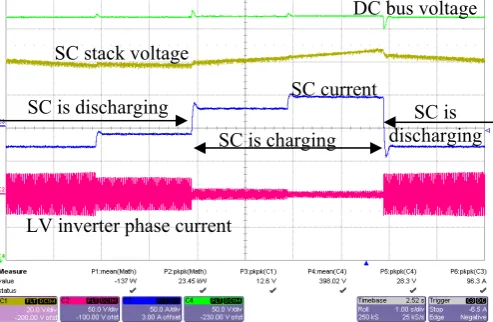
C. Power Peak Levelling of the Power Transferred from a
Weak Medium Voltage Grid
[image:7.595.36.290.54.244.2]conjunction to the feedforwarding mechanism of the power delivered by the LV inverter cause an immediate reaction from the Supercapacitor converter and this is seen in the critically damped supercapacitor current response. The supercapacitor voltage rising and falling slopes are also revealing the periods of time the supercapacitor subsystem charges and discharges in response to the power peak levelling operation.
Fig. 16.Operation of the Energy Storage Subsystem and the LV Interleaved converter: a) DC-bus voltage; b) Supercapacitor stack voltage; c) Supercapacitor current; d) LV inverter grid currents.
IV. CONCLUSIONS
Deploying energy storage in distribution networks is expected to improve the handling of excess renewable energy generated at consumer end and offer extended ride-through operation (including islanding operation) in addition to the already common expectations of better voltage regulation and improved power quality. This paper proposed the concept of integrating the energy storage within a solid state substation and presents the experimental evaluation of a 25kVA demonstrator rated at 1.9kVrms. The improved operation
consists of excellent harmonic performance of the MV and LV inverters, very fast response to step changes in active and reactive power and the ability to provide power peak shaving or ride through operation with full voltage and power availability at the consumer end whilst the MV feeder experiences a grid fault as characterized by the grid codes.
In terms of efficiency, the operation in MV/LV substation mode resulted in efficiencies of 92-93% over a wide range of powers. The efficiency level may be improved in larger size designs that may also use more modern semiconductor and magnetic devices. Also, the added features (active filtering of harmonics, rebalancing unbalance load currents etc) may enable additional energy savings in the equipment of the utility company or the end user. When operating the system as an energy storage system connected to an MV grid, the LV converter technology that requires a 50Hz step up transformer experiences lower roundtrip efficiencies (<81%), mainly due to the poor efficiency of the 50Hz transformer which was specified/chosen on low cost basis. Further improvements of this technology are possible by using lower current densities (winding losses) and lower core flux (core loss) or by employing more expensive core materials such as metglas. This aspect highlights the fact that a potential manufacturer of
an energy storage system that works as a system integrator will need to control very tightly the supply chain if the targeted roundtrip efficiency needs to be maximised. The multilevel converter technology, assuming it can be built to match the voltage level of a MV grid without the need of a 50Hz transformer, can provide higher round trip efficiency (86%) and may potentially react much faster to step changes in reactive current due to the significantly lower line side inductance needed but requires a significantly more complex control and hardware implementation.
It can be concluded that the main features and benefits of a solid state substation with integrated energy storage have been proven experimentally at realistic power (25kW) and voltage levels (1.9kVrms).
REFERENCES
[1] A. Dekka, R. Ghaffari, B. Venkatesh,. B. Wu, “A survey on energy storage technologies in power systems”, IEEE Electrical Power and Energy Conference (EPEC), pp. 105 – 111, 2015, DOI: 10.1109/EPEC.2015.7379935.
[2] G. H. McDaniel; A. F. Gabrielle, “Dispatching pumped storage hydro”, IEEE Transactions on Power Apparatus and Systems, vol. PAS-85, no. 5, pp. 465 – 471, 1966. DOI: 10.1109/TPAS.1966.291683
[3] A.J. Pimm, S.D. Garvey, M de Jong, “Design and testing of Energy Bags for underwater compressed air energy storage”, Energy, Vol 66, pp. 496-508, march 2014. DOI: 10.1016/j.energy.2013.12.010.
[4] E. Chemali, M. Peindl, P. Malysz, A, Emadi, “Electrochemical and electrostatic energy storage and management systems for electric drive vehicles: State-of-the-art review and future trends”, IEEE Journal of Emerging and Selected Topics in Power Electronics, in press, 2016. DOI: 10.1109/JESTPE.2016.2566583
[5] C.Klumpner, G.Asher, GZ Chen, ”Choosing the power electronic interface for a super-capattery based energy storage system”, Proc. of IEEE PowerTech (organized by the IEEE Power Engineering Society), paper #799, Bucharest, Romania, June 2009.
[6] M. Rashed, C. Klumpner, G. Asher, “Hybrid cascaded multilevel converter with integrated series active power filter for interfacing energy storage system to medium voltage grid”, Proc. of IEEJ International Power Electronics Conference IPEC’10, pp. 1236-1243 (paper 23P1-5 on conference CD), Sapporo Japan, June 2010.
[7] M. Rashed, C. Klumpner, G. Asher, “High performance multilevel converter topology for interfacing energy storage systems with medium voltage grids”, IECON 2010 - 36th Annual Conference of IEEE Industrial Electronics, paper #011169, pp. 1819-1825, Glendale, AZ, USA, 7-10 Nov. 2010.
[8] M. Rashed, C. Klumpner, G. Asher, “ Power losses evaluation of three multilevel converter topologies for direct interface with medium voltage grids”, Proc. of European Power Electronics and Applications Conference EPE’11, paper#0618 on CD-ROM, ISBN: 9789075815153, Birmingham/UK, Sept 2011
[9] M. Rashed, C. Klumpner, G. Asher, “Repetitive and resonant control for single phase grid connected hybrid cascaded multilevel converter”, IEEE Trans on Power Electronics, Vol. 28, No. 5, pp. 2224-2234, 2013. DOI 10.1109/TPEL.2012.2218833.
[10] D. De, C. Klumpner, C. Patel, P. Kulsangcharoen, M. Rashed, G. Asher, “Modelling and control of a multi-stage interleaved DC-DC converter with coupled inductors for super-capacitor energy storage system”, IET Power Electronics Journal, Vol. 6, No. 7, pp. 1360-1375, 2013, DOI: 10.1049/iet-pel.2012.0529.
[11] D.De, C. Klumpner, M. Rashed, C.Patel, P. Kulsangcharoen, G.Asher, “Achieving the desired transformer leakage inductance necessary in DC-DC converters for energy storage applications”, IET Proc. of Power Electronics Machines and Drives Conf. PEMD’12, paper #213, Bristol/UK, March 2012, DOI 10.1049/cp.2012.0212.
SC is charging
SC is discharging SC is
discharging DC bus voltage
SC stack voltage
SC current