C. J. Hyde, T. H. Hyde and W. Sun
Department of Mechanical, Materials and Manufacturing Engineering, The University of Nottingham, Nottingham, NG7 2RD, UK
ABSTRACT
In service components such as steam pipes, pipe branches, gas and steam turbine blades, etc. which operate in engineering applications such as power plant, aero-engines, chemical plant etc., can operate at temperatures which are high enough for creep to occur. Often, only nominal operating conditions (i.e. pressure, temperatures, system load, etc.) are known and hence precise life predictions for these components, which may be complex in terms of geometry or weld characteristics, are not possible. Within complex components it can also be the case that the proportion of the material creep life consumed may vary from position to position within the component. It is therefore important that non-destructive techniques are available for assisting in the making of decisions on whether to repair, continue operating or replace certain components. Small specimen creep testing is a technique which can allow such analyses to be performed. Small samples of material are removed from the component to make small creep test specimens. These specimens can then be tested to give information on the remaining creep life of the component. This paper presents the results of small ring specimens tested under creep conditions and shows the comparison to standard (full size) creep testing for materials used under high temperature in industry.
1. INTRODUCTION
Figure 1: Schematic representation of a conventional creep curve.
Figure 2: “Standard” uniaxial creep test specimen (GL ≈ 30 – 50mm; dGL ≈ 6 – 10mm; L ≈ 100 – 130mm).
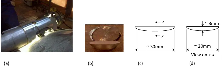
Figure 3: Scoop sample (a) Extraction of, (b) Close-up image, (c) Schematic representation of a typical scoop sample and (d) Schematic representation through x-x.
Another example application for small specimen creep testing is when creep information is required for the airfoil material of heavy-duty gas turbine components. The complex geometry of the internal cooling channels in turbine blades and vanes reduces the available material of what are sometimes already relatively small components. In such a case the component must be taken out of service and small specimen/s manufactured from the component, the results from which can assist decisions on similar/replacement components such as how much longer the component can safely stay in service and for ranking assessments [2].
t
Primary creep Secondary creep Tertiary creep c ε = Fracture = constant)
t
Primary creep Secondary creep Tertiary creep c ε = Fracture = constant)
t
Primary creep Secondary creep Tertiary creep c ε = Fracture = constant)
ε
cL
GL
d
GL x x ~ 30mmView onx-x ~ 3mm
~ 20mm
[image:2.499.48.432.425.540.2]small amounts of material, namely sub-size conventional test specimens [3], impression creep (IC) specimen tests [4], small punch (SP) specimen tests [5] and small ring (SR) specimen tests [6], the performance of which is the subject of this paper. Each specimen type has its own unique advantages and disadvantages and in some cases it may not be obvious which one is the most appropriate test method to use. This paper shows the results SR testing of a Nickel-based superalloy (which is not possible with other small specimen types, as discussed in section 2.2) and gives a description of the major advantages of this specimen type.
2. SMALL RING CREEP TESTING
[image:3.499.185.325.271.369.2]SR creep testing (see Figure 4) has some unique advantages over other small specimen creep test types as discussed below. The test consists of diametrically loading of a (circular or elliptical) ring and measuring the load line deformation of the specimen.
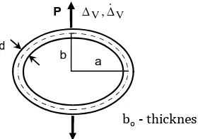
Figure 4: Schematic diagram of a SR specimen.
Typical geometrical values are as follows: a = b = 5mm, d = 1mm and bo= 2.5mm. For this test geometry, an analytical solution for the load line deformations has been obtained, based on the complementary strain energy approach [6]. A reference stress approach was used to establish the conversion relationships between the applied load and the equivalent uniaxial reference stress and between the experimentally measured load-line creep deformation rate, ∆̇ , and the equivalent uniaxial creep strain rate,ߝሶ, [6], these conversions are as follows:
ߪ=ߟܾܲܽ
݀ଶ (1)
ߝ̇൫ߪ൯= ݀
4ܾܽߚΔ̇ (2)
where η and β (conversion factors) are constants and vary with the specimen dimensions, as shown in Figure 5,aandbare the major and minor axis dimensions of the elliptical specimen, as shown in Figure 4,bois the specimen depth anddis the specimen thickness as shown in Figure 4.
V V,
d
a b P
Figure 5: Variation of the η and β parameters with a/b.
[image:4.499.214.299.372.526.2]2.1. Experimental procedure
Figure 6 shows a photograph of the experimental set-up shown in Figure 4 for the SR specimen test. The SR specimen is placed into the test machine and a load applied diametrically to the specimen via loading pins with large resulting deformations in comparison to that of the sub-size uniaxial and impression creep test types. This is due to the flexible nature of the SR specimen type which results in a large equivalent gauge length of the SR specimen type. These high levels of deformation allow for tests to be performed at lower equivalent stresses than the other specimen types and allows for low strains to be obtained from these relatively large deformations.
Figure 6. Experimental set-up for the SR test.
2.2. Advantages of the small ring testing technique
An analytical solution for the deformation of the specimen has been obtained by use of the complimentary strain energy approach and mechanics-based (reference stress) conversion relationships for load and deformation to the corresponding uniaxial stress and creep strain rate, which are relatively insensitive to the geometry changes which occur during deformation can be made.
0.2 0.4 0.6 0.8 1
0.5 1 1.5 2
h
an
d
b
and therefore very easy to manufacture and test. Also, it is a highly sensitive test and hence the deformations measured during the test are large meaning that testing can be performed at low equivalent stresses. Hence low strains can be related to these larger deformations. The deformations from this test are large due to both the flexibility and the large equivalent gauge length (EGL) of the specimen. Due to the large deformations, the test is relatively insensitive to experimental noise.
In addition to above, a unique major advantage of the SR type of small specimen creep test type (and the main focus of this paper) is that, any material can be tested provided that the loading pins are similarly creep resistant to the specimen (could be made from the same material). For the other small specimen types, impression testing for example, the indenter must be significantly more creep resistant than the specimen. This makes testing materials such as Nickel-based superalloys extremely difficult for specimen types other than the small ring specimen.
3. INCONCEL 738 MATERIAL
Inconel 738 was selected for SR creep testing as Laborelec required the creep conditions of a service-aged turbine blade. It is one of the first nickel-based superalloys used for gas turbine hot gas path sections. Inconel 738 is considered as a standard reference material in literature and its creep properties have been widely studied. Mainly consisting of nickel (providing high strength at high temperature), Inconel 738 also contains alloying elements such as Chromium, Aluminium, Cobalt, Titanium, Tungsten and Tantalum in order to add further strength properties as well as corrosion and oxidation resistance. A scanning electron microscope equipped with an energy dispersive spectroscope provided a semi-quantitative analysis of the base material. The results of a semi-quantitative analysis using an energy dispersive spectroscope are provided in Table 1.
Table 1: Chemical composition of blade material compared with literature data, semi-quantitative analysis (wt.%).
Ni Al Ti Cr Co Mo Ta W Nb
Blade material 60.39 3.13 3.46 17.20 8.58 1.94 1.88 2.52 0.83
IN738[7] bal 3.40 3.40 16.00 8.50 1.70 1.70 2.60 0.90
4. SPECIMEN MANUFACTURE
Figure 7: Third stage gas turbine blade from a heavy-duty gas turbine.
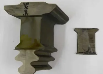
Figure 8: Piece of root extracted along the main direction of the blade.
Figure 9: Ring specimens and remains from EDM operations.
5. SMALL RING CREEP TESTING RESULTS FOR INCONEL 738
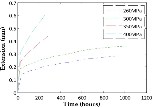
[image:6.499.48.363.375.525.2]Figure 10: SR creep test data for Inconel 738 (nickel-based superalloy) at 800°C.
Due to the effect of the specimen deformation which occurs during the test, a small amount of continual curvature (decreasing deformation rate) is present within the ‘secondary region’ and a completely saturated (constant) strain rate is not quite achieved. It can be seen form equation (1) that the expression used to calculate the applied test load,P, which is assumed to remain constant throughout the test (calculated based in the initial specimen geometry) is based on a desired test reference stress,σref. Whilst boanddare constant throughout the test and the variance ofηwith deformation as the test goes on is negligible (see Figure 5), the change in the ring major axis,a, should not be neglected and hence P should be updated based on the instantaneous specimen geometry. However, (as within this paper) if it is intended that the data is used to obtain the constants for a material model such as the Norton secondary creep model [8] as shown by equation (3), and for corresponding conventional plots of stress vs. minimum strain rate be made from the SR data, values for the secondary MSRs are required and can be obtained.
ߝ ̇ =ܣߪ (3)
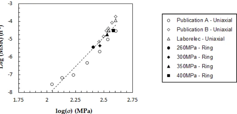
By considering the data within the secondary (small amount of curvature) creep region (see Figure 10), local values of extension and extension rate at regular time intervals can be used to calculate the values ofߪandߝ̇ at each interval position. The averages of theߪvalues and the ߝ̇ values from each time interval can then be taken in order to give the final values. These values can be used to produce a plot of stress vs. MSR on a log-log scale has been produced as shown in Figure 11 where these results are compared to equivalent conventional (full-size) uniaxial tests (see Figure 1) for the same material at the same temperature and shows that the SR data compares extremely well with this conventional creep test data.
0 200 400 600 800 1000 1200 0
0.1 0.2 0.3 0.4 0.5 0.6
Time (hours)
Ex
te
ns
io
n
(m
m
)
Figure 11: Data shown in Figure 10 plotted as stress vs. MSR (minimum creep strain rate) on a log-log scale and compared with equivalent uniaxial data (see Figure 1).
Work is currently being conducted in order to allow for adaptive load tests to be carried out for this SR creep test type in order that the σrefbe constant throughout the test. This is expected to result in a clear secondary (constant strain rate) region being present in the resulting creep data (equivalent to Figure1 0). This will eliminate the need to interpret the data as described above and will allow for interpretation of the data to be identical to that of a conventional creep test in order to produce plots of the data in the form as shown in Figure 11.
6. CONCLUSIONS
This paper describes and demonstrates a recently been developed ring type small specimen creep test [6, 9, 10]. This specimen type displays many advantages compared to other small specimen creep test types. These advantages include the fact that any material, including highly creep resistant materials such as nickel-based superalloys, can be tested, as is the main topic of this paper. The current work, which shows the method applied to the root of an ex-service blade made of Inconel 738 material, is extremely encouraging when compared with conventional uniaxial data. In addition, an analytical method which relates the specimen load and dimensions to the load-line displacement has been obtained.
As mentioned in section 5, the reference stress will change, due to the changes in the dimensions of the specimen, which occur during a test, if a constant load is applied to the specimen throughout the test (see equation (1)). This results in a small amount of curvature (reducing strain rate) in the creep data in the secondary creep region. In order to rectify this, software is currently being developed at the University of Nottingham which will allow for the load to be adapted during the test according to equation (1) as the specimen deforms. It is believed that this will further improve the already extremely encouraging results presented in this paper in terms of both a more clear secondary creep region and the comparison of the small ring creep test data with the uniaxial equivalents.
The authors would like to thank S. Nardone and E. De Bruycker from Laborelec, Belgium for providing the material test specimens, uniaxial data their technical expertise. The authors would also like to thank Shane Maskill for his assistance with the experimental testing.
REFERENCES
[1] T. H. Hyde, W. Sun and S. J. Brett, “Some recommendations on standardisation of impression creep testing”, European Creep Collaborative Committee on Creep and Fracture in high Temperature Components – Design and Life Assessment, 21st-23rdApril 2009, Dubendorf, Switzerland.
[2] W. Sun, T. H. Hyde and S. J. Brett, “Application of impression creep data in life assessment of power plant materials at high temperatures”, Proceedings of the Institution of Mechanical Engineers, Part L , Journal of Materials: Design and Applications222, 175-182.
[3] Askins M. C. and Marchant K. D. Estimating the remanent life of boiler pressure parts, EPRI Contract RP2253-1, Part 2, Miniature specimen creep testing in tension, CEGB Report., TPRD/3099/R86, CEGB, UK, 1987.
[4] Hyde, T.H., Sun, W. and Becker, A.A. Analysis of the impression creep test method using a rectangular indenter for determining the creep properties in welds,Int. J. Mech. Sci.,38, 1089-1102. 1996.
[5] Parker, J.D. and James, J.D. Creep behaviour of miniature disc specimens of low alloy steel, ASME, PVP279,Developments in a Progressing Technology, 167-172, 1994. [6] T. H. Hyde, and W. Sun, “A novel, high sensitivity, small specimen creep test”,J. of
Strain Analysis44(3), 171-185.
[7] Sims C.T., Stoloff N.S., “Superalloys II: High Temperature Materials for Aerospace and Industrial Power”, John Wiley & Sons, USA, 1987
[8] F. H. Norton, “Creep of steel at high temperatures”,McGraw-Hill Book Co., New York. [9] T. H. Hyde and W. Sun, “Some considerations on specimen types for small sample
creep tests”,Int. Conf. WELDS 2009: Design, Testing, Assessment and Safety of High Temperature Welded Structures, 24th-26thJune 2009, Fort Myers, Florida, USA.