TEMPORAL AND FREQUENCY CHARACTERISTICS OF
DISTRIBUTED FEEDBACK DYE LASERS
Michael E. Lusty
A Thesis Submitted for the Degree of PhD
at the
University of St Andrews
1989
Full metadata for this item is available in
St Andrews Research Repository
at:
http://research-repository.st-andrews.ac.uk/
Please use this identifier to cite or link to this item:
http://hdl.handle.net/10023/14312
Temporal and Frequency Characteristics
of Distributed Feedback Dye Lasers.
ProQuest Number: 10166842
All rights reserved
INFORMATION TO ALL USERS
The quality of this reproduction is d e p e n d e n t u p on the quality of the co p y subm itted.
In the unlikely e v e n t that the author did not send a c o m p le te m anuscript
and there are missing p a g e s , these will be n o ted . Also, if m aterial had to be rem o v ed , a n o te will in d icate the d eletio n .
uest
ProQ uest 10166842
Published by ProQuest LLO (2017). C opyright of the Dissertation is held by the Author.
All rights reserved.
This work is protected a g a in st unauthorized copying under Title 17, United States C o d e Microform Edition © ProQuest LLO.
ProQuest LLO.
789 East Eisenhower Parkway P.Q. Box 1346
Eci^liiriiüüii
I, Michael Edward Lusty, hereby certify that this thesis has been composed by myself, that it is a record of my own work, and that it has not been accepted in partial or complete fulfilment of any other degree or professional qualification.
Signed ^ Date
1 was admitted to the Faculty of Science of the University of St. Andrews under Ordinance General No 12 on the 1 st October 1985 and as candidate for the degree of Ph.D. on 1 St April 1986
Signed Date "^344^ / f f j
I hereby certify that Michael Edward Lusty has fulfilled the conditions of the Resolution and Regulations appropriate to the degree of Ph.D.
Signature of Supervisor Date
£QP.y,cight
Acknowledgements
1 would like to thank my supervisor Dr Malcolm H. Dunn for all his encouragement, help and support, which he gave so freely both during the research and in the writing of this thesis.
Many thanks also extend to all of the other members of staff within the department and especially those of the electrical and mechanical workshops and the teaching laboratories. Thanks to the staff of the University Computer Laboratory and in particular Dr John R. Ball.
1 am grateful to Professor Wilson Sibbett for the loan of the streak camera and to Dave Walker for assistance in using it.
The other 'PCs' also deserve thanks for help, making an enthusiastic and productive working environment, and in seeing me through the rough times. Colleagues worthy of a special mention are Messrs (correct at time of press) Andy Finch and Simon Wenden. There are some people who must be acknowledged for helping to make my time at St. Andrews such an enjoyable one. Firstly, all of the above who I regard as friends as well as colleagues. Some of the people I will never forget include Araz All, Nina Donnelly, Ian Ferguson and Mohammed Nasban who, by extending their friendship, have given me a new outlook on life.
Many thanks also to all the staff of David Russell Hall. Truth be told, they deserve a medal, not thanks, for putting up with me for over four years!
The above list is by no means exhaustive and many others have helped. To all those people, I have forgotten to mention, many thanks.
Abstract
Previous studies of distributed feedback dye lasers (DFDL’s) have identified that the linewidth of the device scales, to a first approximation, with the level of pumping employed. A more recent development is that the DFDL can be used to produce single ultrashort pulses. To produce such pulses the main requirement is that the laser is operated close to its threshold. An apparent contradiction exists here since, by lowering the pump power to achieve narrow linewidth operation, the near threshold region must be avoided since pulsing operation acts to increase the linewidth (to at least the Fourier transform of the pulse duration).
This thesis further investigates the mechanisms which contribute to the temporal and linewidth properties of the laser. It is identified that by judicious choice of operating conditions a regime exists where the DFDL may be operated with a linewidth approaching that of the transform limit for the nanosecond pulse durations involved.
After introducing the different types of distributed feedback lasers the thesis first reviews previously understood DFDL behaviour. Different DFDL geometries are considered with a view to their particular temporal and linewidth properties. A strategy for the development of a narrow linewidth DFDL is presented.
The experimental laser system is described detailing the operation and characteristics of the frequency doubled Q switched Nd:YAG pump laser and the two different DFDL geometries. A high resolution computer aided interferometry (CAIN) system is described which provided single shot linewidth measurements. This system was used extensively in the experiments reported.
DFDL linewidth is seen to depend on the thermo-optical properties of the dye's host solvent and as such a full characterization of commonly used solvents is presented.
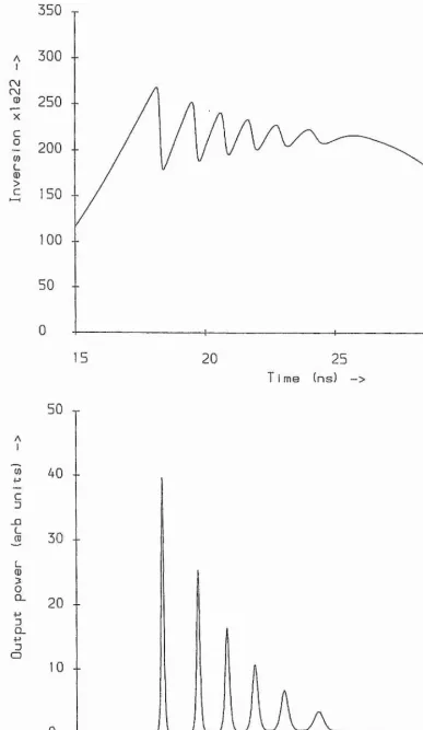
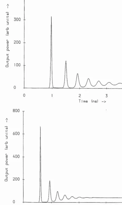
The temporal behaviour of the laser is considered theoretically with the aid of a coupled rate equation model which describes the interplay between the population inversion and the cavity photon flux. The model is used to predict short (picosecond) and smooth (nanosecond) pulse operation of the laser.
Contents
Declaration
Acknowledgements Abstract
Chapter I~An introduction.
1.1 Introduction to the Distributed Feedback Laser... 1
1.1.1 The tunable dye laser.
1.1.2 The distributed feedback laser.
1.1.3 The distributed feedback dye laser of Kogelnik and Shank.
1.1.4 Other types of DFB laser.
1.2 The Distributed Feedback Dye Laser:
Review of Previous Work...6
1.2.1 Introduction.
1.2.2 Developments of DFDL geometries.
1.2.3 DFB theory - Linewidth and temporal behaviour.
1.2.4 Linewidth behaviour of DFDLs.
1.2.5 Temporal behaviour of the DFDL.
1.2.6 Summary.
1.3 Temporal and Frequency Characteristics of Distributed
Feedback Dye Lasers: Thesis Review... 23
Chapter II~The experimental laser system.
2.1 Introduction... 27
2.2 The Nd:YAG Pump Laser...27 2.2.1 Introduction.
2.2.2 The Standaid Quantel YG480.
Contents
2.3 The Distributed Feedback Dye Laser... 35
2.3.1 Introduction. 2.3.2 The DFDL Components. 2.3.3 Basic Experimental Details. 2.4 Summary and Conclusion... 38
Chapter Ill-Computer aided interferometer.
3.1 Introduction... 393.2 Design of CAIN...40
3.2.1 Interferometer. 3.2.2 Image relay and observation. 3.2.3 CCD camera. 3.2.4 Video framestore. 3.2.5 Computer system. 3.2.6 Algoritlim for linewidtli determination, 3.3 Results and Summary...66
Chapter IV-Thermo-optical properties of dye laser solvents.
4.1 Intioduction... 684.2 Themial effects in dye lasers... 68
4.3 Origin of heating of dye solvent... 69
4.4 Experimental metliod...71
4.5 Refractive index, polarizability and density...71
4.6 Results... 72
4.5.1 Organic solvents.
Contents
4.5.3 Solvent mixtures.
4.7 Summary and conclusion...77
\
Chapter V-DFDL rate equation analysis.
Introduction. ... 78
5.2 Rate equation model... 78
5.3 Numerical Solution of Rate Equations ...82
5.3.1 The fourth order Runge-Kutta metliod.
5.3.2 Model parameters.
I
I 5.4 Rate Equation Solutions... 84
5.4.1 Picosecond pulse regime.
5.4.2 The role of pumping.
5.4.3 Nanosecond pulse regime.
5.4.4 Equation constants.
5.5 Summary. ... 90
Chapter VI-Experimental results.
6.1 Introduction and background... ...91
6.2 Experimental apparatus... 93
6.3 Picosecond pulse regime:
Time and frequency domain measurements...100
6.3.1 Introduction.
6.3.2 Background and experimental details.
6.3.3 Streak camera and interferometer results.
Contents
6.4 Smooth pulse regime:
Time and frequency domain measurements...105
6.4.1 Introduction. 6.4.2 Experimental Details. 6.4.3 Results. 6.4.4 Summary. 6.5 DFDL stability...110
6.5.1 Introduction. 6.5.2 Stability measurements. 6.5.3 Origin of wavelength instability. 6.6 Summtuy and conclusion...112
Chapter Vll-Conclusion.
1.1 Introduction... 1147.2 Summary of results... 114
7.3 The rate equation analysis: Its fit with experiment...115
7.4 Consideration of DFDL grating length...116
7.5 A general model of DFDL behaviour...117
7.5.1 General model. 7.5.2 Specific considerations of the laboratories' DFDL system. 7.6 Conclusion... 122
Plates
Chapter I-An introduction.
1.1 Introduction to the Distributed Feedback Laser...1
1.1.1 The tunable dye laser.
1.1.2 The distributed feedback laser.
1.1.3 The distributed feedback dye laser of Kogelnik and Shank.
1.1.4 Other types of DFB laser.
1.2 The Distributed Feedback Dye Laser:
Review of Previous Work...6
1.2.1 Introduction.
1.2.2 Developments of DFDL geometries.
1.2.3 DFB theory - Linewidth and temporal behaviour.
1.2.4 Linewidth behaviour of DFDLs.
1.2.5 Temporal behaviour of the DFDL.
1.2.6 Summary.
1.3 Temporal and Frequency Characteristics of Distributed
Chapter I
1.1 Introduction to the Distributed Feedback Laser. 1.1.1 The tunable dye laser.
A tunable laser has four requirements: 1) A broad bandwidth active medium.
2) Some means of pumping or supplying energy to the active medium. 3) Some form of feedback mechanism, so as to sustain oscillation.
4) Wavelength or frequency selective elements so as to produce a narrow linewidth of radiation, important for many applications.
The organic dye laser is an important category of tunable lasers. The active medium (denoted as (1) in the above list) consists of an organic dye, such as one of the rhodamine series, contained in a host solvent. The operation of a dye laser can be considered with reference to figure (1) which is a schematic diagram of the Eigenstates of a typical dye molecule. Energy is supplied to the dye, in a process normally referred to as pumping (requirement (2) above), either from flashlamps or by another laser. On absorbing a pump photon, the molecule is excited into a rotational-vibrational state contained within the first excited electronic state (S^). This is followed by a rapid (-1 picosecond) decay to the potential energy minimum of the Sj state in a process known as thermalisation. This relaxation is rapid because the large dye molecule experiences greater than 10^^ collisions/second with the solvent molecules. The energy from this nonradiative decay is Uansferred into the kinetic energy of the solvent. Relaxation of the molecule to the ground (G) state can occur via one of three routes; stimulated emission, spontaneous emission (also known as fluorescence) or nomadiative decay. Through the process of stimulated emission the dye can produce optical gain at certain wavelengths. Spontaneous emission typically occurs with a lifetime of the order of 1 to 5 nanoseconds. Nonradiative decay mainly occurs directly from the lowest excited singlet state (Sj) to the ground state (G). The molecule can also decay nonradiatively to the lowest electionic state of a system of triplet states (Tj). For optimal lasing efficiency it is desirable that stimulated emission dominates over fluorescence and nonradiative decay. Once the molecule is in its ground state thermalisation rapidly returns the molecule to its potential energy minimum. As will be seen in the next section, in conventional lasers the feedback (requirement (3)) is
Chapter I
provided by means of two (or more) carefully aligned mirrors. The frequency selection (requirement (4)) becomes increasingly complex according to the frequency selectivity required, using prisms or diffraction gratings for coai'se and interferometric methods for fine tuning. The important developments in the realisation of tunable narrow linewidth dye laser sources are now traced.
Chapter I
improves the frequency resolution of the grating. This modification, which reduced the bandwidth by a factor of 3 over that of the Hansch resonator was first demonstrated by Gallagher et al. [6]. By reduction of the cavity length of a grazing incidence grating geometry to approximately 5 cm, Littman [7] produced a tunable dye laser which, when pumped with a Nd:YAG laser, produced a time averaged linewidth of < 150 MHz. The reduction in cavity length increases the number of round trips and passes through the frequency selective element.
The resonator geometries described above represent what, for the purposes of this thesis, will be termed conventional geometries. Other novel geometries have been developed which fulfil the four requirements of a tunable line-narrowed laser source. One such geometry is the distributed feedback dye laser, the properties of which are the subject matter of this thesis. Another interesting geometry is that of the modeless, variable bandwidth laser of Ewart [8]. The operation of the laser can be considered with reference to figure (3). Light which originates as spontaneous emission from the central gain region experiences a number of trips (typically 4) through the cavity. During each pass the light receives amplification and is line-nairowed as the light passes through the gain region and frequency selective device. The frequency selective device is a 1800 lines mm-i holographic diffraction grating used at grazing incidence. Wavelength tuning is ac complished by the rotation of the prism used in conjunction with the diffraction grating. The bandwidth of the device is determined by the setting of the grating. Simultaneous rotation of the grating and prism varies the number of lines of the grating illuminated hence altering its resolution. Using four passes through the system the linewidth of the device has been lowered to approximately 6 GHz although, significantly, the time averaged bandwidth of the device was quoted in [8] as around 10 GHz.
The distributed feedback laser is now considered.
1.1.2 The Distributed Feedback Laser.
Chapter I
of the refractive index and/or gain along some or all of the length of the active medium. For reasons that will become appaient shortly certain wavelengths can be 'reflected' from the modulated region. Because of certain similarities with the diffraction grating the modulated region in DFB lasers is often referred to as a grating region. The analysis of these types of optical Bragg structures is identical to that of Bragg diffraction of X-rays from crystal planes. Light of wavelength X is diffracted at an angle 0 from a grating which has a period A when the Bragg condition is satisfied, i.e.,
2ASin 0 = n l (1.1)
where n is an integer. As can be seen from (1), light which is at normal incidence (0=90°, sin0=l) to the gating planes experiences back reflection when its wavelength is equal to twice the grating period, i.e.,
X = 2A (1.2)
The light with a wavelength at or near to the Bragg wavelength, travelling perpendiculai' to the modulations in the medium, will therefore be backscattered in the opposite direction to its original direction of propagation. Figure (4) is a simplified illustration of the growth of two waves inside a gain medium containing a Bragg sti ucture, and is obtained using a coupled wave tlieory which is outlined later [9]. The waves are represented as vectors and are labelled as R and S, representing waves travelling to the right and left respectively. As each wave travels through the Bragg grating, it receives a portion of the oppositely travelling wave through the coherent backscattering. If the feedback has a frequency that is within the gain region of the active medium then both waves will increase enabling laser oscillation to occur. Distiibuted feedback refers to the fact that, as has been described, tlte feedback is distributed throughout the gain length. Lumped feedback would best describe the type of feedback in conventional lasers. Spectral selection occurs due to the wavelength sensitivity of tlie Bragg effect.
To date, several types of DFB lasers have been demonstrated. These include DFB dye lasers (DFDLs) which are the subject of this thesis. Other types of DFB laser include the semi-conductor and gas DFB lasers which are briefly considered in section 1.1.4.
Chapter I
The first distributed feedback dye laser (DFDL) was demonstrated by Kogelnik and Shank [10]. Figure (5) is a schematic diagram of the laser. The interference pattern produced by the overlapping of two coherent beams obtained from a He-Cd laser was recorded onto a dichromated gelatin film. After exposure the gelatin film was developed causing a refractive index variation between the exposed and unexposed regions. The porous developed gelatin was tlien soaked in a solution of the laser dye rhodamine 6G. A spatially modulated region, or Bragg grating, of the type outlined above was therefore created in the gain medium. The ultra-violet light from a nitrogen laser provided the pumping of the structure. Pump powers greater than 1 MW cm"^ resulted in laser output at a wavelength of 630 nm. The linewidth of this first DFDL was less than 0.05 nm. Under similar conditions a uniform film of gelatin lased with a linewidth of 5 nm, centred around 590 nm. Tlie incorporation of a distiibuted feedback structure into the dye medium therefore resulted in a 100 times reduction in the laser linewidth.
Before further considering the DFDL it is interesting to consider some other types of DFB laser. Semiconductor and gas distributed feedback lasers are now briefly considered.
1.1.4 Other Types of DFB Laser.
Chapter I
demonstiated operating in the wavelength region of 1.5 |im using InGaAsP/InP [13]. This spectral region is of particular interest to optical fibre communication systems since the transmission of single mode silicon fibres is at a maximum (0.2 dB/km loss) around this wavelength. Fibre optic transmission systems employing such lasers are now available commercially (from STC, BT&D and Plessey) which offer high speed data transmission at greater than 2.4 Gbits/s for distances exceeding 60 km.
Using a rectangular metallic waveguide with mechanically milled corrugations with a period of 248 pm Affolter and Kneubull [14] obtained the operation of a DFB gas laser using the gas CH3F. Pumping the medium was done optically using a grating tuned single mode CO2 laser (A, = 10.6 pm). The spectral linewidth of the device was at the transform limit of - 22 MHz for the 50 ns output pulse. Research continues into DFB gas lasers with much interest concentrating on the possibility of providing line-narrowed output from a CO2 laser.
Having introduced the DFB laser and its variations, a review of some of the most significant DFDL developments which predate this work is now presented.
1.2 The Distributed Feedback Dye Laser. 1.2.1 Introduction.
Since 1971, and the first DFDL of Kogelnik and Shank, the laser has developed in many important respects, this section presents a review of the physical and theoretical developments of the DFDL which predate this thesis. Physical changes are described first. Developments in previous theoretical descriptions of the laser are then considered. As will be seen in the review, the models which best fit the observed behaviour of the laser are;
i) a rate equation model developed by Bor which describes the laser's temporal behaviour in the near threshold region, and,
Chapter I
As can be seen however, these theories are limited to specific areas of DFDL operation and the need for a further theoretical and experimental investigations into the behaviour of the laser then becomes apparent
The developments of the DFDL are now traced.
1.2.2 Developments of the DFDL Geometry, i) The Shank style DFDL.
The first DFDL, demonstrated by Kogelnik and Shank [9], had the disadvantage that the laser wavelength was pre-determined by the recorded grating period. Within a period of three months of this first demonstration Shank, Bjorkholm and Kogelnik [15] reported a tunable DFDL. When the ability to tune the laser is added, the DFDL the laser fulfills all four of the requirements listed above for a tunable narrow linewidth laser. The structure of the Shank laser is shown on figure (6) and is very simple. The second hannonic light from a single mode ruby laser is split into two using a beam splitter and is then recombined inside the dye cell containing the dye rhodamine 6G. Here, the coherent beams interfere to produce a gain and refractive index Bragg grating along the pumped length of dye, the period A of which is given by,
a_ J L Ae_ (1.3)
2 Sin e
where ng is the solvent refractive index, A,p the pump laser wavelength and 0 is the half angle of intersection of the two pump beams. From (2) and (3) it can be seen that the wavelength of tlie Shank DFDL is given by.
Thus the DFDL contains all of the four functions necessaiy for a tunable nairow linewidth laser, within a single element, namely the pumped gain medium.
Chapter I
varying the refractive index of the dye solvent. By changing 0 Shank et al. achieved a
tuning range of 64 nm in the dye rhodamine 6G. A similar tuning range was also observed by varying the refractive index of the solvent from 1.33 to 1.55 by proportionate mixing of methanol and benzyl alcohol. This method of providing tuning by tlie dynamic production of tlie grating in tlie active medium became the standard approach in subsequent DFDL geomehies.
One limitation to the Shank style DFDL is that for a given pump laser the minimum output wavelength is given by the product of iig and Xp. In a slight modification to the Shank design Bakos [17] mounted an isosceles prism in front of the dye cell enabling a DFDL to be pumped by a laser whose wavelength is close to that of the DFDL. A labelled schematic diagram for the prism coupled DFDL is shown on figure (7). Expression (7) is now no longer valid and is replaced by,
e (1.5)
Up S in [(j) + S in - K “T— )]np
where iip is the refractive index of the prism, <|) is the base angle of the prism and 0 is the angle of incidence of the pump beam on the entrance face of the prism. This type of geometry was employed in the majority of experiments performed in this laboratory where, using a frequency doubled Q-switched Nd:YAG laser (Xp = 532 nm) we have operated our DFDL in tlie wavelength range 580-680 nm.
ii) The Bor style geometry.
By replacing the beam splitter of the Shank style DFDL with a diffraction grating Bor [16] demonstrated a DFDL where the DFDL linewidth is decoupled from the effects of pump laser linewidth and spatial incoherence. This allowed Bor to produce a DFDL which when pumped (near threshold) by a partially coherent N2 laser, produced pulses of duration around 100 picoseconds with a near transform limited linewidth of around 0.05 Â.
Chapter I
is a schematic diagram of the Bor style DFDL geometiy. The diffraction grating splits tlie pump beam into the +1 and -1 orders at an angle determined by the grating equation,
Sin a = Xp e (1.6)
where e is the grating constant (-1/ number of lines per metre). The two identical pump beams are, after reflection from the mirrors, then recombined inside the dye cell producing a dynamic grating region of distributed feedback similar to that of the Shank style DFDL. Assuming that the two mirrors are perpendicular to both the dye cell and diffraction grating the wavelengtli of the laser is tlierefore given by,
(1.7) Sin a
Combining (6) and (7) the output wavelength of the Bor style DFDL is given by,
(18)
It is.therefore seen that the DFDL output wavelength is independent of the pump laser wavelength. Achromatism was the term used by Bor to describe this de-coupling of the pump and DFDL wavelengths. The geometry has another important property in that, to a first approximation, for each point on the dye cell the interfering beams have been diffracted from the same point on the grating. This property, along with the achromatism, relaxes some of the constraints on the spatial coherence and linewidth on the pump laser and as such allowed Bor to pump his DFDL with a N2 laser.
Tuning of the laser while still retaining the desirable achromatic properties of the device is achieved by varying the refractive index of the dye solvent. In his first report of the geometry Bor [16] demonstrated a tuning range of over 80 nm (employing three laser dyes) using this method. Tuning can also be employed by tilting the two beam steering mirrors, however, in doing so, the structure loses its achromatic properties. Achromatic properties are also lost if a prism is mounted on the front face of the dye cell.
Chapter I
wavelength. This condition is completely relaxed in a two diffraction grating geometry
demonstrated by Szatmari and Racz [18]. The geometry for which the authors claim a complete relaxation of wavelength and spatial coherence is illustrated schematically on figure 8(b).
1.2.3 DFB theory - Linewidtli and Temporal Behaviour.
Before considering further DFDL developments and experimental investigations, it is interesting to consider some of the previous tlieoretical predictions made about the laser.
Within the first report of distributed feedback laser action, Kogelnik and Shank presented a coupled mode analysis of the laser which formed the basis for much of the theoretical work to follow. A detailed account of the theory can be found in [9] to which the reader is referred (see also Yaiiv [19] section 13.6). The periodic modulation of the medium is modelled as a combination of modulation in the refractive index n or the gain a as,
n(z) = n + ni Cos kz
a(z) = a + aj Cos kz ( 1.9)
where z is measured along the optic axis, a and n are the average values of gain and refractive index, a^ and n^ are the modulation amplitudes of the gain and refractive index, and k is the Bragg wavenumber (27t/A). The coupled mode picture assumes that the field E in the device is of the foim,
E = R(z) e-W2 + s(z) e W 2 (1.10)
consisting of two counter-running waves with complex amplitudes R and S representing waves travelling to the right and left respectively. As indicated in figure (4) the two waves grow in the presence of gain and, due to the spatial modulation of the medium, couple energy into each other. Using this analysis the authors derived expressions for the threshold and specti al bandwidth of the output of the DFB laser. The main limitations of tlie model me (i) the model is time independent, and (ii) it is a linear theory, tlie model can therefore only predict steady state solutions at laser threshold. Within these limitations two important conclusions were obtained with regmd to the predicted spectral output. The
Chapter I
first is the existence of resonance 'modes' separated in frequency by c/2nL ie the same as in a usual two mirror laser cavity with length L. A distinction became apparent depending on the type of coupling used in modelling. When gain coupling was assumed there is a resonance at exactly the Bragg frequency, whereas if refractive index coupling is assumed then the modes aie situated symmeti'ically about the Bragg frequency. An estimation of the linewidth of the device is obtained by evaluating the wavelength offset AX required to reduce the coupling to half its maximum value and is shown to be,
AX Q
where a is the gain per unit length in the medium and Kq is the propagation constant at the laser wavelength.
More elaborate theories of DFB laser action Iiave since appeared in an attempt to describe more fully the operation of these lasers. The effect of saturation was included by Hill and Watanabe [20J although spatial hole burning and dispersion in the active medium were neglected. Sargent et al. [21] treated the DFB semiclassicially by describing the electromagnetic field classically while treating the active medium according to the laws of quantum mechanics. This approach allowed Sargent's model of the DFB laser to include spatial hole burning and atomic linewidth in the analysis. Duling [22] added time dependence to the semiclassical theory to account for field propagation within the DFB laser cavity. Despite these and other attempts to describe the DFDL little headway has been achieved in the interchange of theory and experiment. For example, the modes of a DFB laser predicted by the coupled wave model have never been observed.
With regards to the temporal form of the laser, a simple rate equation model, first developed by Bor [23] was successful in predicting the temporal profile of the laser. This model consists of a pair of coupled rate equations which describe the inteiplay between the cavity photon flux and the atomic inversion. Bor restricted his attention to near threshold in his interest in the production of single ultrashort pulses. This model is re investigated later in Chapter V to explore its validity outside the near threshold region.
A review of experimental investigations into the processes contributing to both the linewidth and temporal foim of the DFDL now follows.
Chapter I
1.2.4 Linewidtli Behaviour of DFDLs.
This section draws together some general conclusions about DFDL linewidth from several sources including including investigations in our own laboratory [24,25], It will be seen that DFDL linewidth depends on:
(a) properties of the pump laser (e.g. linewidth, coherence, beam divergence etc), and,
(b) the level of pumping of the DFDL, through thermal and dispersive effects on refractive index which are seen to depend on choice of dye parameters used in the DFDL's active medium (i.e. laser dye and type of solvent used).
These are now considered in turn along with the transient behaviour of DFDL wavelength and linewidth saturation.
(a) Pump laser parameters (i) Pump laser linewidth
Several authors, including the original report of Shank [15], have reported that the linewidth of the DFDL scales with the linewidth of the pump laser. However, as yet no quantative measurements have appeared in the literature. An estimate of the effect of how a pump laser, with linewidth AXp, can contribute to the linewidth of the DFDL may be obtained by differentiating equation (4) to obtain,
( 1.12)
Sin 0
Alternatively, if the laser is used with a front mounted prism equation (8) can be used to give,
n Sin + S i n - l ( ^ ) ]lip
Therefore if the laser is operating in the wavelength range of 600 to 650 nm then the minimum expected linewidth is around 1.2 times AXp. In the majority of our DFDL research reported before this thesis our Nd:YAG laser was operated with a conventional Q switch. The linewidth of the laser was measured as approximately 3 GHz (0.03 Â) representing oscillation over 20 longitudinal modes. Thus if all other (often more
Chapter I
dominant) linewidth effects can be neglected the minimum DFDL linewidth using the
pump laser in this configuration is approximately 3.5 GHz.
(ii) Pump laser coherence
As can be seen from figure (6) that pump beam which is transmitted by the beam splitter undergoes one less reflection than that beam which is reflected. The consequence of this is that the interference pattern in the dye cell is formed by the wavefront interfering with the mirror image of itself. This places a restriction on the wavefront coherence of the pump beam if a high visibility grating is to be produced.lt will be seen later that a high grating visibility contiibutes to increased spectral selectivity of the DFDL. Bakos [26] observed an increase in DFDL linewidth by a factor of seven when using a ruby laser with poor spatial coherence over that when using a high quality ruby laser pump source. Shank [15] in his DFDL used a TEMoq SLM ruby laser hence ensuring maximum fringe visibility. Vashchuk [27] demonstrated a special splitting prism enabling the formation of a high visibility grating when derived from a laser of poor spatial coherence.
(iii)Pump laser divergence
The influence of pump beam divergence on the DFDL linewidth may be estimated by differentiating equations (5) and (6) with respect to 0 to obtain,
X,i cos 0
A^d = — A0 (1.14)
sin^ 0 or.
AXd = ---
\
= A 8 (1.15)tan [(j) + S i n - i ( )]
y
(n^ - sin^ 0 ) npfor the basic Shank and prism coupled Shank style geometries respectively. The effect was considered and verified experimentally in this laboratory (see for example [24,25]) by vaiying the effective divergence of the Nd:YAG laser used in the pumping of our DFDL. The beam from the pump laser was passed through two 20 cm (nominal) focal length lenses which were spaced by approximately 40 cm (see figure 9(a)). The divergence was altered by moving one of the lenses with respect to the other and the resulting linewidth measured (see figiue 9(b)). This experiment showed that the linewidth
Chapter I
of the DFDL is dependent on the divergence, coming to a minimum for a separation between the lenses (41.2 cm) corresponding to the beam waist formed by the lens combination falling in the dye cell when the divergence of the pump beams in the cell is a minimum.
(b) Power dependence of linewidth.
Although the DFDL demonstrates a dependence of linewidth on the pump laser parameters considered above, the effects cannot account for the power dependence of linewidth which has been reported by several DFDL experimenters. Shank [15] found that the linewidth of his device was very small at threshold, - 0.001 nm (1 GHz), but tljiis increased to 0.05 nm when the pump power was five to fourteen times threshold. This was confirmed by Bakos [26] who found that the linewidth increased from 0.013 nm to 0.4 nm at high pump powers. The work in this laboratory with our DFDL has shown that, before the onset of linewidth saturation at pump powers greater than ~ 20 mJ, the DFDL linewidth scales with the level of pumping employed. Saturation of linewidth is considered in a following section. Two refractive index effects were identified which enable the pump power dependence of DFDL linewidth to be explained. These effects are:
(i) a time dependent refractive index for tlie solvent due to thermal effects, and (ii) a time dependent contribution to the refractive index of the active medium due to the dispersion associated with the optical gain.
Substituting the time dependent refractive index, ng(t) into equation (4) the time dependence of the output wavelength is written as,
^d(t) Sin 0 (1.16)
Thus the effect of a changing refractive index during the course of the pump pulse is therefore to produce a dynamic sweeping (or chirp) of the DFDL wavelength. On integrating over the whole pulse the sweep is observed as a contribution to linewidth which is given by,
A X d = - ^ A n , (1.17)
Sin 0
Chaptej' I
or,
+ Sin-1
for tlie basic Shank and prism coupled Shank style geometries respectively. The thermal and dispersive contributions to the linewidtli are now considered separately.
(i) Thermal effects in dye laser solvents.
Heating effects are inherent in the absorption and emission of optical radiation in a dye molecule. Localised heating changes the density of the solvent hence causing a change in the solvent refractive index. The refractive index change in the pumped region of tlie dye, of volume V, due to heating is given by,
where E is the pumping energy (per pulse). The other parameters are properties of the solvent used; p is the density, s the specific heat capacity, A the fraction of photon energy converted to heat and dn/dT is the rate of change of refractive index with temperature.
The mechanism by which thermal effects contribute to the linewidth is that, during a pumping pulse, the temperature of the active volume increases, thus reducing the refractive index (for negative dn^/d f) with a consequent reduction in the DFDL wavelength. On integrating over the whole pulse, tills sweep in DFDL wavelength is seen as a contiibution to the linewidtli, given by,
XjAE dn.5
A^d = - ^ d T
pVsng(1.20)
Equation (20) assumes that during the course of the pump pulse there is sufficient time to reach thermal equilibrium. However, for the timescales involved (tens of nanoseconds) for most DFDLs this assumption is probably not valid. General conclusions can be made however and these have been validated experimentally. In this laboratory we have observed a linewidth dependence on solvent dn/dT. When the laser was operated using methanol as the dye solvent a larger linewidth was recorded over that when using water. Methanol has a high dn/dT (-47x1 (H K'^) whereas water has a low dn/dT (-8x10-^ K-i). It would seem plausible that by reducing the pump power and using a larger active
Chapter I
volume that thermal effects can be reduced. However, a more careful analysis of these
effects is needed, and this forms part of the contribution of this thesis.
(ii) Dispersive effects on active medium refractive index.
In the previous section the pump power dependence of DFDL linewidth has been related to thermal effects in the dye solvent. MHntyre and Dunn were the first authors to report that the DFDL linewidth was also dependent on its operating wavelengtli. While operating the Nd:YAG pumped DFDL at high pump powers while using rhodamine B dissolved in water, it was observed that the linewidth increased from 0.15 Â to 0.4 Â when operated at the wavelengths of 580 nm and 6(X) nm respectively. The incorporation of a dispersive contribution to the refractive index of the active medium was sited by M‘^Intyre and Dunn as an explanation of the dependence of the linewidth on wavelength. As will be seen later dispersive effects further explain the pump power dependence of DFDL linewidth.
The refractive index of a medium varies rapidly with frequency for frequencies close to an atomic or molecular resonance of the medium. More particularly, if a resonance has a Lorentziau profile, with a halfwidth Av say, the dispersion resulting from the resonance has the functional dependence on frequency,
n(v) = 1 + (1.21)
2 7Ï V Av
where c is the speed of light, v^ is the resonant frequency and a(v) is the frequency dependent gain of the medium, and depends on tlie relative populations in the upper and lower states of the resonance and also the transition cross-section (if a is negative then the medium exhibits absorption and the more usual condition of anomalous dispersion applies).
A consequence of this dispersion is that the refractive index of the active medium is dependent on the upper and lower state populations, and also on wavelength. In the case of a DFDL this can result in an oscillation frequency which is dependent on the intracavity laser radiation intensity. Moreover, since this intensity changes during the course of a pulse, i.e. increases and then decreases, it is to be expected that the oscillation frequency
Chapter I
will also undergo an "excursion" during the pulse, and if the output is integrated over the length of the pulse, this excursion will be interpreted as a linewidth.
Dispersion in a dye laser active medium is more complicated than implied above; for instead of having a single Lorentzian gain profile, the (fluorescent) emission resonance is Stokes-shifted with respect to the absorption resonance (see figure 10(a)) for the emission and absorption spectra of rhodamine B), and so the resulting dispersion curve has two frequency-dependent components, one arising from absorption and the other from emission. In addition, the absorption and emission spectra do not have Lorentzian profiles and so the exact form of the dispersion relation given in equation (21) does not hold; numerical methods now being necessary to determine dispersion curves. However, certain general conclusions regarding the fonn of the dispersion profile may be deduced from the absorption/gain profile using the Kramers-Kronig relations without knowing the exact gain profile [28]; namely the dispersion is always zero where the frequency derivative of the gain or absorption is zero and the dispersion reaches a peak when the gain or absorption is changing fastest with frequency. Since these general relations exist between gain/absorption and dispersion, it is appropriate to represent the absorption and emission spectra of the dye molecule by a reasonable, analytic approximation (e.g. Lorentzian) and expect the resulting dispersion curve to show the correct general behaviour. Such an approximation allows tlie functional dependence of the dye dispersion to be examined with respect to relative populations and DFDL wavelength without recourse to an extensive numerical solution to the Kramers-Kronig relations, but gives only an estimate of the magnitude of such effects.
Using this Lorentzian approximation, the refractive index of a dye solution may be written as the sum of refractive indices,
„r„-, c (v .,-v )N , a„(v) c(v „-v )(N -N i)o ^(v )
«vv; = iij.--- +
---;---T---2 7t V AVg 2 Tt V AVa
where ng is the bulk refractive index of the solvent, Vg is the frequency of the fluorescent .emission peak, AVg is the halfwidth of fluorescent emission, is the frequency of maximum absorption, and Av^ is the halfwidth of absorption. The density of dye
Chapter I
molecules is N and the population in the upper, Sj, state is N^, The frequency dependent
emission and absorption cross-sections are and respectively. These are
approximated here by Lorentzian profiles with the above half widths and appropriate magnitudes. In figure 10(a) the measured absorption and emission cross sections for rho damine B are plotted. Lorentzian approximations for this data are plotted in part (b) of the figure. The second term on the right hand side of (22) represents dispersion due to gain and the third term represents dispersion due to ground state absorption. Dispersion due to triplet absorption has been ignored because the 10 ns pulse is too short to allow the growth of a significant triplet state population.
As can be seen from equation (22), the dispersive contributions to the refractive index are dependent on the excited state population, Nj, and also the frequency of the DFDL radiation hence indicating its power and wavelength dependence.
The mechanism through which the dispersion affects the linewidth of the DFDL is that, during a pumping pulse, the upper level population, Nj, grows from zero to a maximum and then falls back to zero again, while the ground state population, Nq, suffers a dip during the pulse. As this happens, the refractive index of the medium, given by equation (22) undergoes an excursion, the instantaneous refractive index being determined by Nj and Nq. Any change in the refractive index of the DFDL results in a change in the oscillating wavelength, and so the time averaged linewidth appears to be broadened. This incorporation of a dispersive contiibution in the DFDL linewidth can therefore explain tlie dependence of the linewidth on both pump energy and laser wavelength.
Figure 11(a) shows the dispersive contribution to the refractive index as a function of relative excitation (Nj/Nq) for various wavelengths for the dye rhodamine B. The wavelength dependence of equation (22) is illustiated more clearly on figure 11(b). This figure indicates a maximum contribution by dispersion to the time averaged linewidth at around 600 mm, and this is exactly what is observed (see Table 1). Interestingly, aiound 558 nm the dispersive contribution to the refractive index is zero, i.e. the refractive index
is decoupled from (Nj/Nq). This occurs when the dispersive contribution from emission
is equal and opposite to that of absorption, the linewidth then being determined only by
Chapter I
the three previously mentioned processes. Unfortunately at this wavelength for this dye absorption exceeds emission so laser oscillation cannot occur.
Thus the dispersive model of line broadening has been used to explain the observed dependence of linewidth on both pump power and operating wavelength. Moreover, as is considered next, it successfully predicts the temporal behaviour of the DFDL wavelength during the course of a pumping pulse.
Transient behaviour of the DFDL wavelength.
An important distinction exists in the time evolution of the thermal and dispersive components which contribute to the DFDL linewidth. The dispersive component is seen to sweep (or chirp) the frequency of the laser in two directions. Operating on the high wavelength side of the gain profile the laser down chiips reaching a maximum value at the peak of the pumping pulse before returning to its original value in the latter part of the pulse. The direction of the frequency chirp is reversed when operating at a lower wavelength side of the gain cuiwe. The magnitude of the effect is dependent on the laser wavelength and, before the onset of saturation (see next section) scales directly with the level of pumping. However, since the temperature of the solvent contained within the ac tive volume has insufficient time to reach thermal equilibrium with its surroundings the frequency chirp produced is in the downward direction only (downward because the dn/dTs of all solvents are negative).
In investigating the transient behaviour of the DFDL wavelength these two components were observed directly. A full explanation of the method used is given in [24] which is included as an appendix to the thesis. Using the dye rhodamine B the two way frequency chirp associated with dispersion was, as expected, observed to be dependent on wavelength. A larger two way chirp was recorded for 600 nm than for 580 nm which is just as expected considering the wavelength dependence of equation (22) (see also figure
11). The one way chirp associated with thermal effects was seen to be dependent on solvent dn/dT. The transient behaviour of the DFDL further supports the evidence for the existence of a dynamic thermal and dispersive contributions to its linewidth.
Linewidth saturation.
Chapter I
As was stated above the linewidth of the DFDL scales with the level of pumping employed until reaching a saturation value. The nature and origin of linewidth saturation is now discussed. In the linear region of moderate levels of pumping (5-20 mJ), the dominant processes determining linewidth are thermal and dispersive contributions to refractive index. Pumping the DFDL with energies less than approximately 20 mJ it was found that the linewidth scaled linearly with pump energy. For pump energies greater than 20 mJ the linewidth remained constant. Figure (12) illustrates linewidth behaviour for pump energies around this saturation value. The saturation of linewidth can be explained with reference to figure (13) which plots the measured amplified spontaneous emission (ASE) as a function of pump power. As can be seen from the figure the ASE, similar to to linewidth, also saturates around 20 mJ. This behaviour suggests that the saturated gain above 20 mJ is independent of pumping energy, i.e. the maximum upper state population, Ni, is independent of pumping energy. Below 20 mJ, the saturated gain (as shown by the ASE behaviour) increases with pumping power, implying that the maximum value of Ni also increases with increased pumping. Thus, since Ni behaves in this manner, so must the dispersive component, i.e. it increases with pumping energy up to about 20 mJ and then remains constant. As a result, the laser is expected to sweep during an increasingly shorter fraction of the pulse duration for energies above 20mJ, i.e. the laser frequency is constant at a frequency corresponding to the saturated gain for an increasingly longer fraction of the pulse. For a time averaged spectrum, this is interpreted as a decrease in contribution to the linewidth due to dispersion. Since thermal effects continue to contribute increasingly with pumping power the two effects now offset one another. The observed independence of linewidth on pump power for pump powers above 20 mJ (see figure 12) is consistent witli this behaviour.
Summary of linewidtli effects.
In this section the linewidth behaviour of the DFDL has been explained. The linewidth is seen to depend on two factors:
1) the properties of the pump laser (linewidth, divergence, etc.)
Chapter I
2) the level of pumping employed (through thermal and dispersive effects on refractive index).
Effect (1) mainly coiUribules to the linewidth by affecting the properties of the induced grating. For example, the coherence and linewidth of the pump beam determine the visibility and periodicity respectively of the grating which, in turn determine its spectral selectivity.
The power dependence of linewidth (effect 2) derives from thermal and dispersive contributions to refractive index which chirps the DFDL wavelength during the course of the pulse. When time averaged the chirping is interpreted as the device linewidth. As will be seen later (section 1.3), where the development of a narrow linewidth DFDL is discussed, these factors aie of considerable importance.
1.2.5 Temporal Behaviour of the DFDL.
In the period between 1971, when the DFDL was first demonstrated, and 1980 the DFDL was assumed to have a temporal behaviour which followed the pump laser pulse. In previous studies studies in this laboratory our time domain experiments (temporal resolution - 1.3 nanosecond) have been in agreement with this conclusion. Shank et al. [15] in their paper state that "The dye-laser pulse followed closely the smooth second harmonic pump pulse shape which had a duration of approximately 10 nsec". They continue in the next sentence to say, "Flowever, the dye-laser pulse was not smooth and showed a slight superimposed structure". These two sentences were quoted by Bor when in [29] he reviewed the previous two years work on ultrashort pulse generation in DFDLs. By operating a Ng pumped DFDL close to its threshold Bor produced a DFDL capable of generating single picosecond duration pulses. This worked has continued as an active area of DFDL research until the present day. To date (March 1989) the shortest reported directly generated pulse obtained from a DFDL is 320 fs [30].
Bor [29,30] presented a coupled rate equation model describing the interplay between the population inversion and the photon flux inside the laser 'cavity'. In the region near threshold for the device two operating regimes were identified using the model. Before considering the dynamics of the laser action it is important to draw an important
Chapter I
distinction between the DFDL and a conventional Fabry-Perot cavity laser. In a Fabry-
Perot laser the cavity decay time is a constant, depending mainly on mirror reflectivity. In contrast the decay time of a distributed feedback laser is a function of the modulation providing feedback. In particular, as will be developed in chapter 5, the feedback, (or cavity Q) of the DFDL is proportional to the square of the gain of the laser. The dynamics of the laser action are now considered.
In the early stages of pumping the population inversion and gain of the laser increase. As a consequence of the increased gain the cavity Q increases for the reason described above. Below threshold the cavity gain is exceeded by its loss. As the pumping continues laser threshold is reached and surpassed, the gain now exceeding the loss. The DFDL pulse now develops but in doing so stimulated emission causes a depletion of the population inversion which, in turn, lowers the cavity Q causing termination of the laser action. An important consequence of this switching process termed 'self Q-switching' is that the emitted DFDL pulse can be significantly shorter than that of the pump pulse. In the first regime identified by Bor the laser is operated sufficiently close to (around twice) threshold to allow only a single pulse to develop. By pumping above this level Bor identified a second regime where multiple pulsing of the laser occurs. The dynamics of the laser action is essentially the same as that of single pulse production with the exception that, as a consequence of increased pumping the gain can recover to again exceed the loss causing the generation of another short duration pulse. Pumping at levels much above threshold (i.e. greater than five times threshold) has not been reported by Bor nor has he considered tliis regime using the rate equation model.
1.2.6 Summary.
In this section aspects of the DFDL have been explored. An emphasis has been placed on the factors contributing to the temporal and linewidth behaviour of the DFDL. When reviewing the DFDL literature two regimes of operating the DFDL become apparent. Near threshold operation, leading to the production of short pulses is the first regime. In the second regime the laser is operating typically more than five times that of the threshold
Chapter I
value. Here the linewidth of the DFDL has been seen to depend on two main factors,
namely:
1) the properties of the pump laser (linewidth, coherence, divergence etc.) and, 2) the level of the pumping employed (through thermal and dispersive on refractive index).
These factors have been considered in full and estimates of the magnitudes of the effect of these par ameters has been given. When considering the power dependence of linewidth two power dependent parameters were discussed; a thermally and a dispersively derived dynamic sweep of refractive index which when time averaged contribute to the linewidth of the device.
However, in previous literature, no apparent connection exists between the two regimes. This suggests the need for a further investigation into the operation of the laser. Such an investigation forms the subject matter of this thesis an outline of which is presented in the next section.
1.3 Temporal and Frequency Characteristics of Distributed Feedback Dye
Lasers: Thesis Review.
In the previous two sections an introduction to the DFB laser is followed by a review of the processes affecting the linewidth and temporal behaviour of the DFDL, From this review two, seemingly distinct, operating regions of the DFDL have been identified. These are:
1) a neai' threshold region where self Q switching can lead to picosecond pulsing, and,
2) a well above threshold region where three processes were identified as contributing to tlie linewidth, namely:
(i) Pump laser par ameters (linewidth, coherence, divergence etc.),
(ii) a time dependent refractive index for the solvent due to thermal effects, and (iii) a time dependent contribution to the refractive index of the active medium due to the dispersion associated with the optical gain.
Chapter I
Processes (ii) and (iii) togetlier identify a general trend scaling the linewidth with the level of pumping employed and are the more dominant processes at moderate levels of pumping.
However, it has become apparent that, thus far, no general model exists which provides a description of the DFDL. Having seen that two, seemingly unconnected regimes exist in the experimentally observed behaviour of the laser, it is reasonable to ask if it is possible to reconcile tlie two in a such a model which provides a general description of distributed feedback dye laser action. Such a description should be consistent with all of the previously modes of operation e.g. in the production of ultrashort or narrow linewidth pulses. This apparent lack of understanding has stimulated this further experimental and theoretical investigation into the properties of the DFDL. This thesis presents the results of these further investigations. It will be seen that our experimental laser system could be configured for either short duration or narrow linewidth pulses. In the light of these investigations we present a new model which comprehensively describes the behaviour of the laser and is in good agreement with previous experimental observations.Tliis model should further aid the understanding of the DFDL.
A significant development of this investigation was the production of a DFDL which can operate at or near to its transform limited linewidth of 100 MHz for the 10 nanosecond duration pulse under a much less restrictive range of operating conditions than previously reported, namely 580 to 680 nm using a variety of laser dyes. Such operation was obtained by tlie following strategy:
1) Identifying, both theoretically and experimentally, pulsing regimes so as to avoid them,
2) Reducing pump laser effects to a minimum by employing a narrow linewidth, highly coherent, low divergence pump laser, and
3) Operating the laser at reduced pump powers while minimising, as far as practicable, thermal effects by the use of low dn/dT solvents and restricting oscillation to wavelength regions of low dispersion.
The remainder of this thesis considers the experimental and theoretical investigations into DFDL behaviour.
Chapter I
Chapter 2 contains details of the design and construction of the experimental DFDL system. The geometries of Shank [15] and Bor [16] are considered. In addition the modifications to the Nd:YAG pump laser enabling the production of TEMqo single
longitudinal mode pulses are described.
To facilitate linewidth measurements a computer aided interferometer (CAIN) system was constructed. Chapter 3 contains a full account of the device which was used for the majority of the linewidth measurement in later experiments. This self contained system allows single shot measurements down to 100 MHz level which is approximately the transform limit for the 10 ns DFDL pulses. The system consists of a non degenerate 1.5 GHz free spectral range interferometer and an image grabbing system which is made up from a CCD camera, a video framestore and a computer.
Chapter 4 contains an account of the heating mechanisms inside the dye medium and presents the results from an investigation into the thermo-optical properties of dye laser solvents. These properties are of considerable importance when assessing the thermally derived refractive index sweeps contributing to linewidth. The method of assessment is discussed together with a characterisation of a wide range of dye laser solvents.
Chapter 5 further investigates the coupled rate equation model of Bor. In addition to the near threshold region investigated by Bor, operation well above threshold is considered, conditions appropriate to our line nmowed DFDL. The equations are solved numerically using a fourth order Runge-Kutta method. A variety of parameters are explored in addition to that of increased pumping including the effect of reduced visibility of fringes, grating lengtli etc.
Chapter 6 comprises the main body of experimental work performed on the DFDL under the new pumping conditions (reduced power, line-narrowed pump laser etc.). A full interferometric investigation into the linewidth properties of the DFDL under a range of operating conditions is presented. In addition to this linewidth investigation results are presented where simultaneous linewidth using the CAIN system and temporal mea surements using a streak camera were made. The motivation for this investigation was to ascertain if the pulse envelope contained a lar ge number of picosecond pulses as has been
Chapter I
suggested by Bor [31], or if single narrow linewidth pulses may be produced by pumping well above threshold.
A conclusion to the thesis forms the last chapter. In the conclusion a new model is presented which links the various operating regimes. The model considers both ultrashort pulse and nanosecond pulse generation. The linewidth of the laser can also be predicted depending upon the particular operating circumstances.
The diesis also includes four appendices.
The first is a paper written by I.A McIntyre and myself under the supervision of M.H.Dunn which describes the processes determining the DFDL linewidth. The paper was published in the Journal of Modern Optics.
The second appendix is a paper written by myself and M.H.Dunn which reports on an investigation into the thermo-optical properties of dye laser solvents. This paper was published in the journal of Applied Physics B.
The third appendix contains details of the operation of the CAIN system and includes a listing of the computer software.
The fourth and final appendix contains a listing of the FORTRAN program used in the solution of the coupled differential rate equations describing the temporal behaviour of the DFDL. The algorithm employed was a fourth-order Runge-Kutta method.
Chapter I
Wavelength Linewidth at Linewidth ;
(nm) 5°C(Â) 22°C(Â)
580 0.15 0.22
590 0.22 0.32
600 0.4 0.6
Chapter I References
[1] P. Sorokin and J. Lankard: "Stimulated emission observed from an organic
dye, chloroaluminum phtalocyanine" IBM J. of Res and Dev 10, 162 (1966). [2] F.Schafer, W. Schmidt and J.Volze: "Organic dye solution laser" Appl. Phys Lett 9,306 (1966).
[3] B.B. McFarland: Appl. Phys Lett 10, 208 (1966).
[4] B.Soffer and B.B. McFarland: Appl. Phys Lett 10, 266 (1966).
[5] T.W. Ilansch: "Repetitively pulsed tunable dye laser for high resolution spectroscopy" Appl. Optics, 11,895 (1972).
[6] T. Gallagher, R. Kacliru and F. Gounand: "Simple linewidth - reducing modification for a Hansch dye laser" Appl. Optics, 21, 895 (1972).
[7] M.Littman: "Single mode pulsed tunable dye laser" Appl. Optics, 23,4465 (1972).
[8] P.Ewart: "A modeless variable bandwidth, tunable dye laser": Optics Commun. 55, 124 (1985).
[9] H.Kogelnik and C. V.Shank: "Coupled Wave Theory of Distributed Feedback Lasers" J. Appl. Phys 43,5,p2327 (1972).
[10] H.Kogelnik and C.V.Shank: "Stimulated Emission in a Periodic Structure" Appl. Phys. Lett. 18,4,pl52 (1971).
[11] M.Nakamura, A. Yariv, H.W. Yen, S.Soneth andH.L. Garvin: "Optically pumped GaAs surface laser with corrugation feedback" Appl. Phys. Lett
22,10,515 (1972).
[12] M.Nakamura, K. Aiki, J Umeda, A.Yariv, H.W.Yen and T. Morikawa: "GaAs-Gai_xAlxAs double-hetrostructure distributed feedback diode laser" Appl.Phys.Lett 25, 4887 (1972).
[13] K. Satai, K. Utaki, S. Akita and Y. Matsashime: "1.5 |im range InGsAsP/ InP DFB lasers", IEEE J. Quantum Electron, QE-18, 1272 (1982).
IEEE J. Quantum Electron, QE-17, 115 (1981).
[15] C.V.Shank, J.E.Bjorkholm and H.Kogelnik: "Tunable Distributed Feedback Dye laser" Appl. Phys. Lett. 18, 9, p395 (1971).
[16] Zs Bor: "A novel pumping arrangement for tunable simple picosecond pulse generation with aN^ laser pumped DFDL" Optics Commun. 29,103 (1979). [17] J.Bakos, Z Fuessy, Z Sorlei and J. Szigeti: "DFDL of wavelength tunable from 747 nm to 840 nm" Phys Lett 50A, 227 (1974).
[18] Szatmari and Racz: "Novel achromatic DFDL for subpicosecond operation" Appl. Phys B 43, 173 (1987).
[19] A.Yariv: Optical Electronics Third Edition, Holt, Rinehart and Winston (1985).
[20] K.Hill and A.Watanabe: "Envelope gain saturation in DFB lasers" Appl. Optics 14, 950 (1975).
[21] M.Sargent III, W. Swantner and J.Thomas: "Theory of a distributed feedback laser" IEEE J.Quantum Electron QE-16,465 (1980).
[22] LDurling III and M.Raymer: "Time dependent semiclassical theory of gain coupled DFB lasers" IEEE J.Quantum Electron Q E-20,1202 (1984).
[23] Z.Bor: "Tunable picosecond pulse generation by a N^ laser pumped self Q switched DFDL" IEEE J Quantum Electron. QE-16,517 (1980).
[24] I.MHntyre: Ph.D. Thesis "Dye lasers with induced Bragg gratings" University of St.Andrews (1985).
[25] I.MHntyre, M.E.Lusty and M.H.Dunn:"Linewidth determining processes in DFDLs" J.Mod.Optics 35, 325 (1988).
[26] J.Bakos, Z.Sorlei:"High power DFB laser tunable in the 7426Â to 10500
A
range"Optics Commun. 22, 258 (1977).[27] V.Vashchuck, E.Zabello and E. Tikhonov: "New dye laser systems with dynamic distributed feedback" Sov.J.Quantam Electron, 8,859 (1978).
[29] Z.Bor, A.Muller, B.Racz and F.Schafer: "Ultrashort pulse generation by DFDLs" Appl. Phys B 27, 9 (1987).
[30] S. Szatmari and B. Racz: "Generation of 320 fs pulses with a DFDL" Appl, Phys B, 43, p93 (1987).
Abs.
Tnr» Ips
T|r = 10 ns
Fluor
Tp = Ins / '^P/ h'=lps
Echelle Grating
Fabry - Perot Etalon
Telescope
Dye Cell
[image:45.620.138.465.171.496.2]Mirror N _-Laser
(a)
OUTPUT
ACTIVE
MEDIUM FREQUENCY DEVICESELECTIVE
(b)
OUTPUT
DYE CELL
d if f r a c t io n grating
PUMP BEAMS
Figure 3. The modeless dye laser of Ewart [8]. (a) Shows the basic geometry of the system while (b) shows the system in plan view. Tuning is achieved by rotation of PI.
OUTPUT
OUTPUT
K>
DISTANCE
L / 2
[image:46.620.220.465.368.619.2]UV PUMP
GELATIN', .'DYE
/ / ' / / / / .
liii
" / / i / Z
• GLASS S U B S T R A T E ' / ---L
---LASER
O U T P U T
Figure 5. Cross section of the first distributed feedback dye laser of Kogeinik and Shank [10]. The gain region modulation was provided by exposure to two overlapping beams obtained from a He—Cd laser. The structure was transversely pumped by an Nt
laser. Using a modulation period of approximately 300 nm and the dye rhodamine 6G laser action at approximately 630 nm resulted. The linewidth of the device was less than 0.5 Â.
O U T P U T
MIRROR DYE
C E L L
O U T P U T
L E N S E S
0.347/^
- P U M P L IG H T MIRROR
BEAM S P L I T T E R
dye cel
ourpur o u f p u r
prism
mirror m ir r o r
pump beam
le n s
PUMPING BEAM
ÜYE SOLUTION EXCITED VOLUME DFDL BEAM DIFFRACTION OllDEHS
TUNING
CL'
/_
H O L O G R A P HI C G R A T I N G
24 42 l/min
PUMPING
QUARTZ BLOCK
GRATING 2
DYE CELL
GRATING 1
DFB
diver ge nce = 0 - 5 mrsd
Nd:YAG pum p
I OF 3 '
Porh le n s e s f = 20 cm
C.0 cm
Nd:YAO pumo
Figvtre 9. (a) Arrangement used, to vary the divergence of the pump beam of the DFDL. (b) The dependence of the DFDL linewidth on lens seperadon (and hence divergence of
Pvt e vO I O c C3 (JJ tn 1 X ‘aa; 5
a b s or p t i o n
4
e mi s s i o n
3
2
16
14 18 20 22
3 1
wa v e n u m b er (10 cm '
L o r e n t z i a n a p p r o x i m a t i o n s c o Ü 0) CO I CO CO o L a
Rhodatn I ne
emm I s Ion
; a b s o r p t 1 on
15 16 17 18 19 20 21 22 23 24 25
w a v e n u m b e r >
S70 nm
SâO nm
592 nm
608 nm 600 nm
5 8 4 nm
0-3 0-4 O'S
ral excifat-ion ~
X 0)
“ac
0)
cn
c
(D
R h o d a m i n s B d i s p e r s i o n
5 1 6 1 7 » II
- i i r
9 20 21 22 23 24 25
wa ve n um b e r — >
(Inewidth Â
2-0
1-2
0-8
10 20 30
pump energy40
OFOL o utput
energy (mJI
0-1
00 1"
0-001
ASc
energy (arb units)
SO 100
pump energy (mJ)
![Figure 2. The tunable line-narrowed dye laser of Hansch [5], Coarse tuning is achieved](https://thumb-us.123doks.com/thumbv2/123dok_us/8569521.368069/45.620.138.465.171.496/figure-tunable-narrowed-laser-hansch-coarse-tuning-achieved.webp)
![Figure 3. The modeless dye laser of Ewart [8]. (a) Shows the basic geometry of the](https://thumb-us.123doks.com/thumbv2/123dok_us/8569521.368069/46.620.220.465.368.619/figure-modeless-dye-laser-ewart-shows-basic-geometry.webp)