Abstract – Optimisation algorithms hold the potential to
dramatically reduce computational time whilst ensuring the optimal solution is found. Within this paper, the feasibility of using this novel approach on complex 3-D Computational Fluid Dynamics models, which are required for thermal management of electrical machines, is proven. A model of a simplified generator is parameterised with the aim of minimising the peak stator temperature by varying the axial location of a single stator vent. By generating a single parameterised case, and automating the optimisation, the simulations are run independently after initial setup, hence reducing both computational and user time. Locating a vent in the optimal position reduced the peak stator temperature by 9.4 K. A sensitivity study linking peak temperature to vent position has been carried out developing a polynomial relationship between them for the aforementioned geometry. Mass flow and pressure distribution in the vent have been analysed in detail.
Index Terms—Alternator, CFD, Computational Fluid Dynamics, Cooling, Electrical Machine, Stator Vent, Synchronous Generator, Optimization, Thermal Management
I. NOMENCLATURE
Symbol Description Unit
A Area m2
h Heat transfer coefficient W/(m2K)
l Normalised vent position -
L Core length m
pn Normalised static pressure Pa
pvent,out Average pressure at vent outlet Pa
Tmax Maximum stator winding temperature K
Tmax,B Maximum stator winding temperature
of non-vented benchmark case
K
ΔT Normalised maximum stator winding temperature
K
Q̇conv Convective heat transfer W
vn Normalised velocity -
vtip Tip velocity m/s
z Axial vent distance from core inlet m
II. INTRODUCTION
Traditionally, designers of electrical machines focussed on improving the electromagnetic properties while paying less attention to the thermal design of said machines. In recent years however, the increasing demand for smaller, more efficient and reliable machines necessitated improving their thermal aspects [1].
K. Bersch (email: [email protected]), P. H. Connor (email: [email protected]) and C. N. Eastwick (email: [email protected]) are with the Fluids and Thermal Engineering Research Group. M. Galea (email: [email protected]) is with the Power Electronics, Machines and Control Research Group, all based within the Faculty of Engineering, University of Nottingham, Nottingham, UK. R. Rolston (email: [email protected]) is with Cummins Generator Technologies, Peterborough, UK.
The limiting temperature of an alternator is usually determined by the insulation material, most of which degrade above a temperature of 130-180° C. A 10° C rise in insulation temperature will half the machine lifetime [2]. Furthermore, the resistance of the windings and thus the induced copper losses increase with rising temperature reducing generator efficiency. The identification and appropriate cooling of hot spots is therefore important to achieve the above-mentioned improvements.
Since the main losses of an electrical machine occur in the stator windings [3] it is common practice to vent the stator in bigger machines to remove heat from the core via convection. Conduction alone is not sufficient to remove the heat generated in its centre. The addition of vents results in complex airflow and heat transfer which cannot be predicted adequately with analytical methods such as flow and thermal resistance networks [4].
Computational Fluid Dynamics (CFD) is the most extensive modelling approach for the thermal analysis of electrical machines. A physical domain is divided into a number of control volumes and the governing equations of fluid flow and energy are integrated over all cells. The integral equations are converted into a system of algebraic equations by discretisation and solved using an iterative method [5]. To date, it is the only modelling approach capable of solving convective and conductive heat transfer simultaneously. While CFD enables an accurate prediction of the conjugate thermal performance, its usage is limited by its high computational cost as well as the considerable amount of time and user experience required to set up the model correctly [1], [5].
In the early design stage it is often necessary to analyse a variety of different configurations. One of the most widely used CFD solvers in academia and industry is ANSYS Fluent which is integrated into the simulation environment ANSYS Workbench. Workbench offers several features facilitating simulation setup and minimising the number of cases required to run, hence reducing manual setup as well as computation time.
One of these features is the Response Surface Methodology (RSM) in conjunction with Design of Experiments (DOE). Response surfaces are functions describing the output parameters of an analysis in terms of the input parameters. DOE aims to minimise the number of sampling points necessary to explore the design space and create accurate response surfaces [6]. These techniques have been used successfully to optimise the design of wind turbines using 2-D CFD models [7], [8] and for the electrical analysis of alternators [9], [10].
While RSM enables the simultaneous optimisation of multiple parameters it is currently computationally too expensive (on a desktop PC) to use it for a complex 3-D model as it is required for the simulation of stator vents. It is feasible to optimise one output parameter dependent on one input parameter however. This paper presents the methodology by finding the optimal position of a single stator vent located to minimise the peak stator winding
CFD Optimisation of the Thermal Design for a
Vented Electrical Machine
temperature. As CFD model setup and computation time increase exponentially with the model complexity, a simplified geometry has been used for this investigation. This was necessary to enable the methodology development within a reasonable timeframe.
III. METHODOLOGY
A. Geometry and mesh
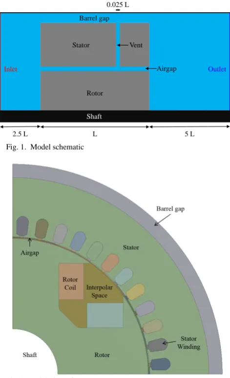
The model geometry has been created based on typical dimensions of a medium sized four-pole synchronous generator. Fluid as well as solid zones were considered. The vent width was chosen to be 2.5 % of the core length. To reduce the computational effort the machine is assumed to be rotationally periodic. Hence only one 90° pole sector was modelled. Furthermore, only the core of the machine without rotor or stator endwindings was represented. Fan and exciter are neglected. Casing, shaft and surrounding fluid are extended 2.5 core lengths upstream and 5 core lengths downstream of the core. To facilitate meshing of the vent region the vent gap supports are neglected as well. Fig. 1 shows a side view of the created geometry. An axial view of the core geometry can be seen in Fig. 2.
Barrel gap
Stator
Rotor
L 5 L
2.5 L
Outlet Inlet
Shaft
Vent
Airgap 0.025 L
[image:2.595.51.287.324.711.2]Fig. 1. Model schematic
Fig. 2. Axial view of core geometry
The creation of geometry and mesh as well as the subsequent simulation and the optimisation process all took place within ANSYS Workbench 17.2. This facilitates the creation of input and output parameters of interest and their interdependencies. Additionally, it enables the creation of a
model robust enough to handle the automatic updates during the optimisation process. Substantial effort has been put into the creation of a fully parametric geometry and mesh. While creating a parametric model adds time to the initial model setup, the total investigation time is reduced. The mesh has been created based on the methodology developed in [11]. Meshing of the stator vent and airgap were particularly challenging. They require special attention due to their high influence on the flow solution [4].
B. CFD
The CFD package used for this investigation is ANSYS Fluent 17.2. Air enters the computational domain through a velocity inlet at a temperature of 300 K. The outlet is defined as a constant pressure boundary. Both are perpendicular to the machine axis of rotation. They are placed far enough away from the zone of interest to not interfere with the flow solution. The heat generated inside the machine (mostly through copper and iron losses) has been taken into account by adding volumetric heat generation to all solid parts. The loss distribution is based on the findings in [12]. Conduction in all solids is assumed to be isotropic.
The standard k-ε model with Enhanced Wall Treatment was chosen for turbulence modelling due to its robustness and the possibility to use wall functions instead of having to resolve the boundary layer for all walls. It is commonly used for radial flux machines and has been validated for them by a number of researchers [12]–[16]. Pressure and velocity were coupled by the SIMPLE algorithm. The spatial discretisation of all variables is second order accurate.
Rotation is modelled using the Multiple Reference Frame (MRF) technique. While the flow inside a generator is transient, this approach allows the case to be simulated as steady-state with respect to the moving frame. The moving parts are frozen in a specific location and the flow field developing in that position can be observed [17]. While less accurate than using the fully transient Sliding Mesh (SM) approach, it is normally used for the analysis of electrical machines [12]–[16] due to the much lower computational effort required.
To avoid divergence during the first iterations the energy equation is turned off initially. This also reduces the computation time as the flow field requires more iterations to converge than the temperature distribution. Convergence is monitored using residuals and variables of interest such as moment coefficients, vent mass flow, winding temperatures etc. Early investigations showed that convergence is reached after solving the airflow only for 500 iterations followed by solving the full Conjugate Heat Transfer model for another 500 iterations. This resulted in a computation time of 4:30 h per design point (DP) on a desktop PC featuring a 3.5 GHz Intel Xeon Hexa-Core and 64 GB RAM. The mesh size is 9.2 million cells.
C. Design Optimisation
of interest such as the average stator winding temperature and the mass flow through the vent.
The minimum and maximum vent position was limited to be 0.1 core lengths away from the core ends to avoid meshing problems. The simulation results confirmed that this is a reasonable limitation of the domain which does not influence the optimisation results (view section IV.A).
Since only one variable input parameter exists, it was decided to perform a Direct Optimisation immediately instead of creating a response surface first. The Adaptive Single-Objective method is the optimisation algorithm chosen for this investigation. It creates a Response Surface from a small number of initial design points. Additional DP are selected based on gradient and used for refinement of the response surface as well as reduction of the search domain until the convergence criteria are met. [6] provides an overview and in-depth explanation of the optimisation algorithms available in ANSYS Workbench.
IV. RESULTS AND DISCUSSION
A. Optimisation
To quantify the benefit of adding a vent into the stator, a model without any vents was solved initially. The maximum stator winding temperature of this model is defined as the benchmark temperature Tmax,B. All following temperatures
are normalised as
B
T
T
T
max
max,
( 1 )with Tmax being the maximum stator winding temperature of
the vented cases. The vent position is normalised as
L
z
l
( 2 )L being the total core length and z the axial distance of the vent from the core inlet.
The optimisation procedure converged after 19 evaluations of different vent positions. The minimal temperature for a vented machine is 9.4 K below the temperature of the non-vented case. The average stator winding temperature decreased by 8.6 K for this configuration. Fig. 3 shows the maximum stator winding temperature for each tested design point chronologically over the course of the design optimisation.
The original response surface is built from the first three design points which are distributed evenly over the domain. Each additional design point is used to either refine the response surface or reduce the domain. While it takes 19 evaluations for convergence to be reached, the temperature difference between the optimal design point found on the initial response surface (DP 4) and the global optimum (DP 10) is negligible.
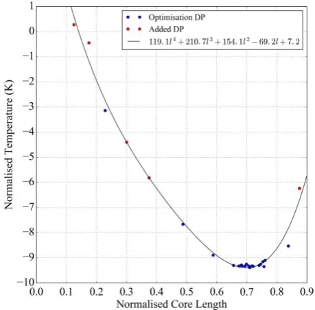
Fig. 4 shows the relationship between maximum stator winding temperature and vent position. As the optimisation algorithm quickly identifies the approximate optimal region, some design points have been added manually to better visualise the influence of vent position on stator temperature across the domain. The addition of DP also validates that the found optimum is indeed the global optimum and not just a local one.
[image:3.595.313.541.55.283.2]Fig. 3. Maximum stator winding temperature of configurations tested during the Design Optimisation in chronological order
Fig. 4. Relationship between maximum stator winding temperature and vent position
There is hardly any variation of stator temperature for 0.65 ≤ lvent ≤ 0.75. This is most likely the reason why the
optimisation algorithm quickly identifies the approximate optimal vent location but requires 15 additional evaluations to reach convergence. After the initial solves, it evaluates one configuration on either side of this region (DP 5 at lvent = 0.59 and DP 6 at lvent = 0.84) and determines them to
[image:3.595.311.541.330.556.2]The correlation between temperature and core length can be described by a 4th order polynomial with the equation
2
.
7
2
.
69
1
.
154
7
.
210
1
.
119
4
3
2
T
l
l
l
( 3 )The polynomial was fitted to the data using the Ordinary Least Square method. It provides a good fit to the simulation results with a R2-value of 0.99
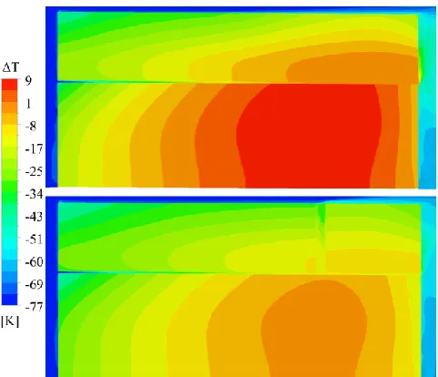
In Fig 5 the temperature contours in the core are compared between the non-vented case and the case with an optimally placed vent. The stator hot spot of the non-vented case is placed in the back third of the windings. The temperature of the air passing through airgap and IP space has increased too much by this point for it to provide sufficient cooling to the windings. By venting the stator in this area the winding surface area in contact with the cooling air, and hence the convective heat transfer, increase as
hAdT
Q
conv
.
( 4 ) with Q̇conv being the heat removed through convection, h the
local heat transfer coefficient, A the surface area and dT the temperature difference between surface and free stream.
Fig. 5. Temperature contours of non-vented case (top) and case with optimal vent position (bottom)
It can be seen in Fig. 5 that the machine hot spot is actually placed in the rotor. Interestingly enough, venting the stator decreases the maximum rotor temperature as well in this case. The vent position optimising the cooling of the rotor hot spot is located in the same region as for the stator. While the rotor temperature has not been considered for this optimisation, it is possible to target several objectives simultaneously and assign them weights depending on their importance [6]. This is particularly useful for contradicting objectives.
B. Vent airflow
As the airflow through the vent is of high importance for the thermal performance of the machine it is considered in detail in the following section. Velocities are normalised as
tip n
v
v
v
( 5 )with v being the local velocity and vtip defined as the rotor tip
velocity. Static pressure is normalised as
out vent n
p
p
p
, ( 6 )p being the local pressure and pvent,out the average pressure at
the joint of vent and barrel gap.
[image:4.595.309.551.141.242.2]Flow through the vent is driven by the pressure difference between the airgap and IP space and the barrel gap. As the pressure is higher in the centre of the machine, air flows radially outwards through the vent. Fig. 6 shows the velocity contours in the axial centre of the vent. Fig. 7 is a close-up of the velocity vectors around the two windings marked with a black circle in Fig. 6 in the same plane.
Fig. 6. Velocity contours in the axial centre of the vent
Fig. 7. Close-up of velocity vectors in the axial centre of the vent around the two windings marked in Fig. 6
When the air passes through the channel between two windings, the mass flow rate is higher at the side of the windings facing the direction of rotation. The flow attaches to the curvature of the windings due to the drastic change in dominant flow direction from circumferential in the airgap and IP space to radial in the vent. This observation is in agreement with the results in [18].
On top of the mass flow imbalance inside each channel, the flow is distributed unevenly between the various channels as well (view Fig. 8). The channel mass flow rate depends on its position relative to the rotor. The channels directly fed by the inter-polar space (6-8) show the highest flow rate with a proportion of 12-14 % of the total mass flow through the vent passing through each. In comparison, the minimum flow rate through the channel trailing the IP space (9) only amounts to 4.4 %. From there on it increases steadily against the direction of rotation until it reaches a value of 8.6 % in channel 3.
[image:4.595.306.551.260.406.2] [image:4.595.50.291.288.495.2]Fig. 8. Distribution of total mass flow through the vent between the channels; Channels are numbered from the left to the right in Fig. 6 (counter-rotation) with 1 being the channel split by the periodic boundary
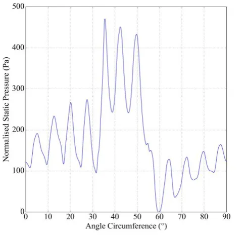
Fig. 9. Static pressure in the airgap around the circumference in the axial centre of the vent; 0° corresponds to the centre of channel 1
V. CONCLUSION
Even in smaller synchronous generators in the sub-MW range, the addition of vents can substantially reduce hot spot as well as average temperatures in the machine core. A CFD investigation of a simplified generator geometry has been carried out with the aim to minimise the peak stator winding temperature by positioning a single stator vent in the optimal location. It was possible to reduce the maximum stator winding temperature by 9.4 K in comparison to a non-vented case. The average stator winding temperature decreased by 8.6 K for this configuration.
The setup and solution of CFD simulations are time consuming processes, which can be a disadvantage during the early design stage where a variety of different configurations need to be considered. This paper presents a
novel methodology to find an optimal solution requiring no additional user input beyond the initial setup of the model using the Design Optimisation feature integrated into ANSYS Workbench. The application of automated simulation setup and optimisation algorithms reduces the investigation time compared to a manual analysis.
Airflow and heat transfer in vented machines is highly complex. As the flow through the vent is of high importance for the thermal performance, mass flow and pressure distribution in the vent have been analysed in detail. It has been found that the mass flow rate through the channels separating the windings depends on their position relative to the rotor pole and is driven by the pressure distribution in the airgap. The highest flow rates arise in the channels located above the inter-polar space.
Future work will use the methodology developed in this paper to investigate the influence that other design parameters have on a broader range of variables on a more complex geometry.
VI. REFERENCES
[1] A. Boglietti, A. Cavagnino, D. Staton, M. Shanel, M. Mueller, and C. Mejuto, “Evolution and Modern Approaches for Thermal Analysis of Electrical Machines,” IEEE Trans. Ind. Electron., vol. 45, 2009.
[2] J. Pyrhönen, T. Jokinen, and J. Hrabovcová, Design of rotating electrical machines. Chichester, 2014. [3] B. C. Mecrow and A. G. Jack, “Efficiency trends in
electric machines and drives,” Energy Policy, vol. 36, no. 12, pp. 4336–4341, 2008.
[4] P. H. Connor, C. N. Eastwick, S. J. Pickering, C. Gerada, and R. Rolston, “Stator and Rotor Vent Modelling in a MVA rated Synchronous Machine,” pp. 573–579, 2016.
[5] H. K. Versteeg and W. Malalasekera, An Introduction to Computational Fluid Dynamics - The Finite Volume Method. 2007.
[6] ANSYS Inc., “DesignXplorer User’s Guide v17.2,” 2016.
[7] S. Tabatabaeikia, N. N. B. N. Ghazali, W. T. Chong, B. Shahizare, N. Izadyar, A. Esmaeilzadeh, and A. Fazlizan, “Computational and experimental optimization of the exhaust air energy recovery wind turbine generator,” Energy Convers. Manag., vol. 126, pp. 862–874, 2016.
[8] M. Jafaryar, R. Kamrani, M. Gorji-Bandpy, M. Hatami, and D. D. Ganji, “Numerical optimization of the asymmetric blades mounted on a vertical axis cross-flow wind turbine,” Int. Commun. Heat Mass Transf., vol. 70, pp. 93–104, 2016.
[9] S.-J. Cho, Y.-W. Cho, M. G. Lee, and J. H. Kim, “Variable impact analysis of linear generator by using response surface method,” Int. J. Precis. Eng. Manuf., vol. 17, no. 9, pp. 1223–1228, 2016. [10] S. Lee, Y. Kim, K. Lee, and S. Kim, “Multiobjective
Optimization Design of Small-Scale Wind Power Generator With Outer Rotor Based on Box – Behnken Design,” vol. 26, no. 4, 2016.
[11] P. H. Connor, S. J. Pickering, C. Gerada, C. N. Eastwick, and C. Micallef, “CFD Modelling of an Entire Synchronous Generator for Improved Thermal
[image:5.595.53.284.54.283.2] [image:5.595.52.296.337.569.2][12] P. H. Connor, “Computational Fluid Dynamics Modelling of a Synchronous Electric Generator,” University of Nottingham, 2014.
[13] M. Shanel, “Investigation of Rotor Cooling in Salient Pole Electrical Machines,” University of Nottingham, 2002.
[14] C. Micallef, “End winding cooling in Electric Machines,” University of Nottingham, 2006.
[15] S. J. Pickering, D. Lampard, J. Mugglestone, and M. Shanel, “Using CFD in the Design of Electric Motors and Generators,” Comput. Fluid Dyn. Pract., 2001. [16] J. Mugglestone, D. Lampard, and S. J. Pickering,
“Effects of end winding porosity upon the flow field and ventilation losses in the end region of TEFC induction machines,” IEE Proc. Electr. Power Appl., vol. 145, no. 5, pp. 423–428, 1998.
[17] Fluent, “ANSYS FLUENT User’s Guide v17.2,” 2016.
[18] M. Schrittwieser, A. Marn, E. Farnleitner, and G. Kastner, “Numerical Analysis of Heat Transfer and Flow of Stator Duct Models,” Ind. Appl. IEEE Trans., vol. 50, no. 1, pp. 226–233, 2014.
VII. BIOGRAPHIES
Kevin Bersch received a B.Sc. and M.Sc. degree in Mechanical Engineering and Business Administration from the RWTH Aachen University in 2012 and 2015 respectively. He started his PhD in the Fluids and Thermal Engineering Research Group of the University of Nottingham
in 2015. His research focusses on the thermal improvement of electrical machines using CFD and experimental investigations.
Peter H. Connor received an M.Eng. and Ph.D. from the Department of Mechanical, Materials and Manufacturing Engineering Department, University of Nottingham, UK, in 2009 and 2014 respectively. He is a Research Fellow in the Fluids and Thermal Engineering Research Group and is a member of the Cummins Innovation Centre, both of which are based within the Faculty of Engineering at the University of Nottingham. Carol N. Eastwick received her BEng and PhD in Mechanical Engineering in 1990 and 1995 respectively. She is currently an Associate Professor in the Faculty of Engineering at the University of Nottingham, having worked on modelling and experimental investigations of thermofluids associated with rotating machinery for nearly twenty years.
Michael Galea received his PhD in electrical machines design from the University of Nottingham, UK, where he has also worked as a Research Fellow. He is currently a Lecturer in Electrical Machines and Drives within the PEMC research group of the University of Nottingham. He is the Deputy Director of the Institute for Aerospace Technology at the University of Nottingham, where he is also a Lecturer in Aerospace Systems Integration. His main research interests are design, analysis and thermal management of electrical machines and drives.