AMPEX _
Ampe. CO,pmaMn' On@"'TheS"loa.Camp,noes tAMPEX 230 plus
Video Display Terminal
Operation Manual
TABLE OF CONTENTS
Foreword
SECTION I· INSTALLATION
1.1 Installation Requirements
1.1.1 ACPowerCordandPlug 1.2 Installing the Display Unit
1.2.1 The Display Screen 1 .2.1.1 Status Line 1.2.1.2 User line
1.2.2 Interface Cable Connections
1.2.2.1 Optional Interlace Connections
1.2.3 Keyboard Port Connection
1.3 ON/OFF Swnch
1.3.1 Power On Procedures
1.3.2 Resetting the Terminal 1.4 The Keyboard
1.4.1 Main Keypad
1.4.1.1 Alphabet Keys: National Character Sets 1.4.1.2 Cursor Keys
1.4.1.3 Ed. Keys 1.4.2 Control Keys
1.4.3 Numeric Keypad
1.5 Locking and Unlocking the Keyboard 1.6 Indicators
SECTION 11· SETTING UP
2.1 Entering Set-up Mode 2.1.1 Set-up Lines
2.1.2 Modifying Parameters
2.1.3 Exiting and Saving Changes 2.1 .4 Exiting with Temporary Changes
2.1.5 Retrieving Previous Values 2.1.6 Retrieving Defauh Values 2.2 Set-Up Lines
2.2.1 Set-Up Line 1 2.2.2 Set-Up Line 2 2.2.3 Set-Up Line 3 2.2.4 Set-Up Line 4 2.2.5 Set-Up Line 5 2.2.6 Set-Up Line 6 2.2.7 Set-Up Line 7
2.2.8 Setting/Clearing Tab Stops
SECTION 111 • OPERATION
3.1 Operating Modes
3.1.1 Communications Mode 3.2 Displaying Data
3.2.1 Video Background 3.2.2 Video Attributes
3.2.2.1 Embedded Attributes 3.2.2.2 Non-Embedded Attributes
3.2.3
3.2.4
3.3 Scrolling and Flipping
3.3.1 Scrolling and Page Size 3.3.2 No Scroll
3.3.3 Customizing Scrolling
3.3.3.1 Defining a Scrolling Region 3.3.3.2 Locking Lines
3.3.4 Flipping from Page to Page 3.4 Entering and Editing Data
3.4.1 Write-Protecting Data 3.4.2 Moving the Cursor
3.4.2.1 Cursor Keys
3.4.2.2 Moving the Cursor using an Escape Sequence 3.4.2.3 Locating the Cursor with an Escape Sequence 3.4.2.4 Entering Data at the Hidden Cursor
3.4.3 Editing Data
3.4.3.1 Defining the Editing Mode 3.4.3.2 Edh Keys
3.5 Clearing Data
3.6 Entering Function Commands 3.6.1 Using lhe FUNCT Key
3.6.2 Using the Function Keys
3.6.2.1 Programming the Function Keys 3.6.3 Executing a Function Key from the Host 3.7 Sending
3.7.1 Programming Delimiters 3.7.2 Programming the SEND Key 3.8 Printing
3.9 Programming the Editing Keys 3.10 Setting the Time
SECTION IV· EMULATING OTHER TERMINALS
4.1 Enhanced Em.Jlation
4.2 ADDS
4.2.1 Viewpoinl Aland A2 4.3 Ampex
4.3.1 210 4.4 Hazeltine
4.3.1 1500 4.5 TeleVideo
4.5.1 910 4.5.2 920
4.5.3 9241914
4.5.4 925 4.5.5 950
4.6 Wyse
4.6.1 WY-50
SECTION V - TROUBLESHOOTING
5.1 Maintenance 5.2 Troubleshooting
5.2.1 Printing Test
APPENDIX A· SPECIFICATIONS APPENDIX B • INSTALLING OPTIONS
APPENDIX C· NATIVE MODE ESCAPE AND CONTROL SEQUENCES APPENDIX D· EMULATIONS ESCAPE AND CONTROL SEQUENCES APPENDIX E· ASCII CODE CHART
APPENDIX F· ASCII CODE DIFFERENCES BY CHARACTER SET APPENDIX G· ASCII CODES FOR ROW/COLUMN NUMBERS APPENDIX H· MONITOR MODE SYMBOLS
LIST OF ILLUSTRATIONS
Figure 1-1. Terminal Dimensions Figure 1-2. Terminal, Front View Figure 1-3. Power Cord/Plug Types Figure 1-4. Terminal, RearView
Figure 1-5. Terminal, Display Areas Figure 1-6 Terminal, Status Line
Figure 1-7. Keyboard Port on Display Terminal Figure 1-8. Character Keys
Figure 1-9. Cursor Keys Figure 1-10. Editing Keys Figure 1-11. Control Keys
Figure 1-12. Numeric Keypad
Figure 2-1. Set-Up Line 1 Figure 2-2. Set-UpUne 2
Figure 2-3. Set-Up Une 3
Figure 2-4. Set-Up Line 4 Figure 2-5. Set-Up Line 5
Figure 2-6. Set-Up Line 6 Figure 2-7. Set-Up Line 7 Figure 2-8. Set-Up Line 8
Figure 3-1. Special Graphics
Figure 3-2. Screen Relative to Memory Size Figure 3-3. Alternative Divisions of Memory
Figure 3-4. Scrolling Data Figure 3-5. No Scroll Figure 3-6. Scrolling Region Figure 3-7. Locking Lines
Figure 3-8. Flipping from Page to Page
Figure4-1. Ampex 21 a Graphics Figure 4-2. TV924 Special Graphics Figure 4-3. TV950 Special Graphics Figure 4-4. WY -50 Special Graphics
Table 1-1. Table 1-2. Table 1-3. Table 1-4. Table 1-5. Table 3-1. Table 3-2. Table 3-3. Table 3-4. Table 3-5. Table3-S. Table 3-7. Table3-B. Table 3-9. Table 3-10 Table 3-11. Table 3-12. Table3-13. Table3-14. Table 3-15 Table3-1S. Table 3-17. Table 4-1. Table 4-2. Table 4-3. Table 4-4. Table 4-5. Table4-S. Table 4-7.
Table 4-8. Table 4-9.
Table4-10. Table4-11.
Table 4-12.
LIST OF TABLES
Primary Port Pin Signal Assignments Printer Port Pin Signal Assignments Cursor Keys
Edit Keys Control Keys
Operating Mode Escape Codes Description of Operating Modes Video Attribute Escape Sequences Cursor Keys
Edit Keys
Clear Commands Function Key Sequences
Valuesofp1
Values of p2 Send Commands
Effects of Send Commands
Default Delimiter Values for SEND Programming the SEND Key Print Commands
Effects of Print Commands
Default Codes and Effects for Editing Key Default Codes and Effects for SHIFT/Editing Key Normal versus Enhanced Emulation
Function Key ASCII Code Values ViewPoint Function Key Codes Video Attributes forTV920 Values of p1 forTV924 Fn Keys Values of p2 for TV924 Fn Keys T eleVideo Video Attributes T eleVideo Clear Command Codes Values of p1 forTV950 Fn Keys Values of p2 forTV950 Fn Keys
WY-50 Function Key ASCII Code Values WY -50 Clear Command Codes
FOREWORD
The Ampex 230 plus desktop video display terminal is an inpuVoutput peripheral capable of interfacing with a variety of computer systems and peripheral devices. The Ampex 230
plus terminal has its own set of operating characteristics ("native mode"), is fully compatible
with the Ampex 230 terminal, and emulates the following terminals:
Manufacturer ADDS
Ampex Corp.
Hazeltine
TeleVideo Systems, Inc. Wyse Technology
HOW TO USE THIS MANUAL
Terminal Model
Viewpoint A 1 , Viewpoint A2
210 1500
910,920/912,9241914,925,950 WY-50
This manual contains the information necessary to operate the Ampex 230 plus Video
Display Terminal.
The manual describes how the Ampex 230 plus terminal works in its native mode.
Although it is likely that an action's effect (e.g., INSERT CHARACTER) is the same when emulating another terminal, differences are possible. Consult the manual for the terminal being emulated if the effect is not as expected. NOTE: The effect of an action available in an emulation but not in the native mode is
llil1
described in this manual.Sections are summarized as follows:
FOREWORD Provides general information about the Ampex 230 plus video display terminal, including a physical description and overview of features.
SECTION J Explains how to physically install the terminal.
SECTION II Describes how to customize the terminal's settings for operation.
SECTION III Explains how to operate the terminal, including how to choose the proper communications mode, different ways of displaying data, how to enter and edit data, how to use function keys, sending and printing text, and how to re-program the programmable keys.
SECTION IV Describes how to choose an emulation and notable operational differences between the Ampex 230 plus native characteristics and the emulation's characteristics.
SECTION V Provides a brief troubleshooting guide.
Operating Modes The terminal may be operated in a variety of "modes", which may be seleded from the computer or via the keyboard. The available modes include:
Page Memory
Printing
Mode
Block
Conversation
Local
Monitor
Protect( Text)
Wrtte Protect(ed Text)
Description
Stores a block of data entered from the keyboard in the terminal display memory. Data may then be edited "on-screen" -- before being transmitted to the host.
Transmits data to the host computer as it is entered from the keyboard on a character-by-charaderbasis.
Executes terminal functions locally -- transmission between the terminal and the host computer is prohibited.
Control characters entered via the keyboard or received from the host are displayed on screen but not interpreted or executed.
Protects text entered in Write Prated mode from erasure, change, or transmission to computer or printer. Used, for example, in data entry on electronic forms.
Entered text is marked so that it will be protected when terminal is in Protect mode.
The terminal can store 96 lines of data in its own memory, divisible into units of one page (96 lines), two pages (48 lines per page), or four pages (24 lines per page).
A printer can be attached directly to the terminal via the terminal's "Printer"
port.
Printing may be controlled in a variety of ways :Extension (Copy) Print
Page Print
Transparent Print
Prints data sent to the terminal by the host while displaying it on the screen.
Printing initiated via the keyboard or from the host; prints the text from the Home position through cursor position; printing may be either formatted or unformatted.
Scrolling
Set-up
Video Attributes
A variety of scrolling options may be set, including:
Extended Page A 48-line or 96-line page may be scrolled without loss of data.
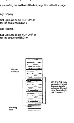
Flip Data exceeding the last line of a page may
continue to scroll on the same page or "flip" to a newpage.
Scroll Rate Data may be scrolled at any of four smooth rates or at a "jump scroll" rate.
Scroll Region Any block of adjacent rows may be defined as the scrolling region; or any set of individual rows or block of adjacent rows may be "locked" while data on the remaining lines scroll.
Terminal operation is customized using menu-driven Set-Up lines, accessed via the SET-UP key. Lines display current values of terminal's operating parameters. Parameter values may be changed and saved.
Video attributes can be assigned from either the terminal keyboard or the host computer. Video attributes may be either embedded (assigned to a field) or non-embedded (character-specific). Attributes can be assigned singly or in combination.
Blank (i.e., "invisible": characters not displayed) Flash
Reverse Underline
INSTALLATION
1.1.1 AC Power Cord and Plug
The Ampex 230 plus terminal is equipped with either a 115 VAC/60 Hz power plug (for use
[image:9.542.75.476.342.604.2]in the United States) or a 230 VAC/50 Hz power plug (for use outside the United States). Make sure that the cord and plug are appropriate for the power output you intend to use
(Figure 1-3).
NOTE: If you will be using the terminal in either the United Kingdom or Australia, you may need to customize the power plug in order to fit the receptacle.
WARNING
Before changing the plug, disconnect the cord from
the wall outlet (AC power). Electric shock may result if the power cord is connected to AC power when the
plug is cut from the cord.
~A,CGROUND_GREEN
"lsl
LINE-BLACK~
~I==' '==I[jW~
NEUTAAl_WHITE
NEMA TYPE 5_1SP
AC GROUND IGAEENIYELlOW)
A. POWER CABLE A
~
EUTRAL_BlUE€
~
$D=.
= = : : : j '£CjiFF=lll
LlNE-BAOWN DIN TYPE 49-400
CEE TYPE /-1
SCHUKO
B. I'OWEA CABLE B
Figure 1-3. Power Cord/Plug Types
~
ACGRQUND"GREENLINE_BLACK
,
, ,
NEUTRAL_WHITE CEE TYPE 22
IEC TYPE no
62956
~ GROUND_GREEN!YEllDW
~
""-'"OW,
~
NEUTRAL-SLUE CEE TYPE n IEC TYPE 320
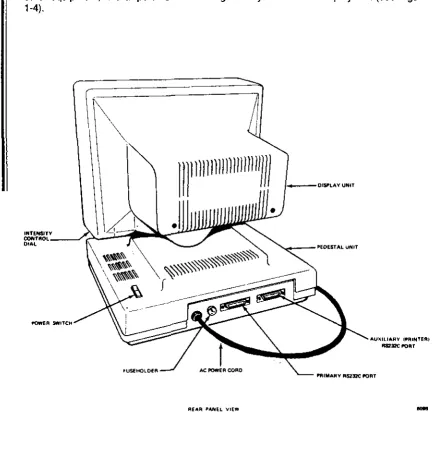
1.2 INSTALLING THE DISPLAY UNIT
The Display unit consists of a Cathode Ray Tube (CRT) mounted on a pedestal (Figure
1-2). The Display tilts and swivels forthe most comfortable viewing angle.
The pedestal holds the ON/OFF switch for the terminal, two "ports" for attaching the unit to other equipment, and a "port" for connecting the keyboard to the display unit (see Figure
1-4).
1IIIllll
n
11
n
11111111)))
[image:10.550.75.512.109.576.2]I
Figure 1~4. Terminal, Rear View
I'IIIMAMY 1ISl:J2C !'ORT
-INSTALLATION
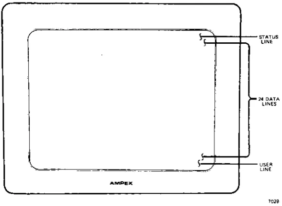
1.2.1 The Display Screen
The Display Screen is where characters you type or characters received from the host
computer appear. Twenty-six rows may be displayed (Figure 1-5), divided as follows: Row
Top
Middle 24 rows Bottom
Contents
Status line (reports terminal's status) Typed or received data
User Une {for operator or application program entries}
Underneath the lower right side of the CRT is a brightness control(see Figure 1-4).
A CRT Saver built into the terminal turns off the display after about 10 minutes if no new characters are sent to the screen. Note: Ordinarily, Set-Up Une 1 flashes if the CRT Saver comes on. You can set the terminal so that the set-up line does not flash in this situation
(Set-Up, Line 3: SAVER BLN).
NOTE
You can tum off the CRT Saver in Set-Up (Une 2: SAVE OFF). If you turn off the CRT Saver, be sure not to leave screen intensity at a high level for long periods of time. Doing so may wear the phosphor-coated screen unnecessarily.
This, and other options affecting the display screen, depend on choices you make when
you SET-UP (Section II).
.
,
I
[image:11.542.125.415.383.595.2]AM"E><
Figure 1-5. Terminal, Display Areas
>-STATUS
LINE
14 DATA
LINES
USER UN.
"" ... v .... I
1.2.1.1 Status Line
The Status Line (top of the screen) reports on the operating status of the terminal: caps lock, time of day, printing, operation attributes rmodes"), video attributes, DSR status, and cursor position. See Figure 1-6 for a complete listing of possible status entries.
The Status Line may be turned off (Set-Up, Line 1: STAT OFF). The CAPS indicator may also be turned off (Set-Up, Line 3: CAPS OFF). The contents of the Status Line may be sent to the computer (see "SENDING" in Section III).
,~,
C ... s cOC~ " " . , .. O,C"'OR Of "'... OH
Eon
' - '
.OIT MOO.
ootc
.0"
c, .. ,E01. ["r, '''G.
, .. S.. ' .... R' ,,,.,
... $. 'NS'AT •• 0.
I ,
<3,-" "","o".,OLOeK'O
...
,
..
"".,
0""""",,"'000' Bc' BLOC"
.". 'ucc OU'C'>('''O' SHO"~'
~o. .. .. " DUPe . . , .. ,,' S~o",,' COC LOC.C '''OT ,HO""J
.... , ""'lE 'AO!fe'
",ON "'0 .. "0" , .. OTSHO_J
"G
'H'"~'''... ".
0'0 ,.,T"'6 ... " E ... c'
;C. H"
ss<: S.ctT SCR"" 'R' '''OHCT
DSR ' " , . . ,
'-'"' '---'
","" .. c "TTR'8UtES • • c .... MO U ... "0,,, .. '0
, 'c"S~'''C "."'''SEO'''O.O
H H .. c'·"oT' .... rv
I
CUASOA LOC.flO~ ""G, AOW COCU"'~'".".
'"
A'AD'
PTG '.GE "" .. , .GK .ROGR ... 'u .. e"o .. ",y
_ • T"."S . . A ... ' 'A, .. ,
CI'P COf'V'"''''
u" U .. OOA .... TT.O .,., .. , 80'" a";>'''.cTm .... c
.R, .. -reA 'OR1 0 ..
Figure 1-6. Tenninal, Status Line
1.2.1.2 User Line
The User Line (bottom of screen) is a ''free'' line reserved for operator or application program entries. The length of the User Line depends upon the line length chosen in Set-Up: 80 or 132 columns.
Ordinarily, the User Line is not displayed.
To tum the User Line ON,
enter the sequence ESC g
To turn the User Line OFF,
enter the sequence ESC h
To enter data onto the User Line,
1. Enter the sequence ESC f 2. Type in the desired message.
INSTALLATION
1.2.2 Interface Cable Connections
The Ampex 230 plus terminal has two standard RS232C serial port interfaces (Figure 1-4) .
. One, the "PRIMARY" port, is used to connect the terminal to a host computer. The other, the "PRINTER" port, is used to connect the terminal directly to a printer (a printer may be
connected directly to the computer).
To connect the terminal to the computer andlor printer, use a standard RS232C serial
cable with a male connector on the terminal end. The type of connector on the opposite
end at the cable depends on the connector of the computer (/modemlprinter).
The maximum length for an RS232C cable connecting the terminal and other equipment is 50 feet.
NOTE
It is recommended that you use only shielded and jacketed cable. Using such a cable will help minimize electromagnetic interference, protecting your tenninal and any other electronic devices near the terminal.
•
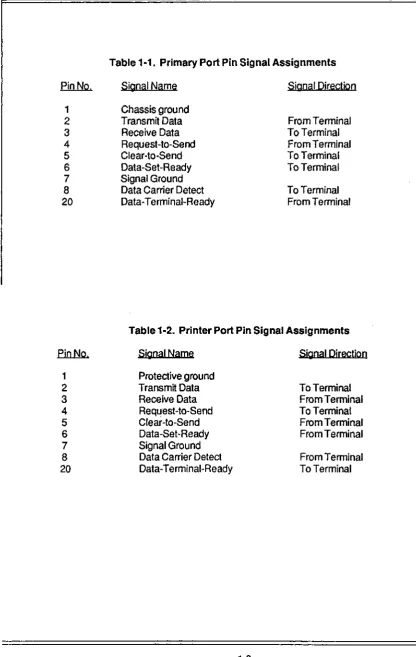
When connecting the terminal to other equipment, make sure that pins on the terminal connector are matched properly with the pins on the connector of the other equipment (see Section V). Pin assignments for the primary and printer port are given below.
Table 1-1 provides pin signal assignments for the primary port. Table 1-2 provides pin signal assignments forthe printer port.
1.2.2.1 Optional Interface Connections
The RS232C connection of the primary port may be replaced by either of two optional interlace connections:
RS422 Interlace (for more speed)
20 rnA Current Loop Interlace (for greater cable length)
These options are available in kits from Ampex and may be ordered through your Ampex Sales Representative. When ordering, be sure to specify the part number for the desired kit:
RS422 [nteriace Kit: Ampex Part No. 3515412-02A Current Loop Interlace Kit: Ampex Part No. 3515413-02A
;:)1:'''' IIVI't I
Table 1·1. Primary Port Pin Signal Assignments
pin No. Signal Name Signal Direction
1 Chassis ground
2
Transmit Data From Terminal3 Receive Data To Terminal
4 Request-to-Send From Terminal
5 Clear·lo·Send To Terminal
6 Data-Set·Ready To Terminal
7 Signal Ground
8 Data Carrier Detect To Terminal
20
Data·Terminal-Ready From TerminalTable 1·2. Printer Port Pin Signal Assignments
Pin No. Signal Name Signal Djrectjon
1 Protective ground
2 Transmit Data To Terminal
3 Receive Data From Terminal
4 Request-Ia·Send To Terminal
5 Clear-ta·Send From Terminal
6 Data-Set-Ready From Terminal
7 Signal Ground
8 Data Carrier Detect From Terminal
SECTION I
1.3 ON/OFF SWitch
The ON/OFF (power) switch is a rocker-type switch located to the right rear of the un~.
1.3.1 Power On Procedures
When you tum on the terminal,
it
performs a self-test to make sure ~ is working properly_ This self-test operation checks the following areas/functions:CMOS RAM (a check sum of the terminal's set-up information) DATA RAM
DISPLAY RAM ROM
VISUAL ATTRIBUTES (displays the test pattern")
NOTE: the results of the self-test do not depend on whether or not the terminal is connected to a computer and/or printer; Le., you can check the terminal is working properly without first connecting it in your system.
To tum on the terminal:
1. Plug the power cord into the properoutret or receptacle.
Make sure all interlace cables are connected properly.
2. Set the on/off switch to ON (rear Mswing" down).
IFTHE SELF-TEST FINDS NO PROBLEMS,
the cursor will appear in the HOME position (the upper left corner of the screen). The terminal is ready for use.
INSTALLATION
IF TH E SELF-TEST UNCOVERS A PROBLEM,
one of the following messages may appear: CMOS CHECKSUM ERROR
DATA RAM ERROR
ROM ERROR
DISPLAY RAM ERROR
II you get CMOS CHECKSUM ERROR, do thelollowing:
press SHIFT/NO SCROLL (= SETUP) press SHIFT/D
press SHIFT/NO SCROLL (= SETUP) press SHIFT/S.
tum the terminal off and then back on.
If the message does not appear, you are ready to proceed. If the message reappears, contact your service representative. If you get one of the other messages, do the following:
press CTRUSHIFT/RESET
If the message does not appear, you are ready to proceed. If the message reappears, contact your service representative.
1.3.2 Resetting the Terminal
Resetting the terminal returns the terminal to its state at power-on (nothing displayed, nothing in memory) and initiates asetf-test;Qlli power remains on.
SECTION I
1.5 Locking and Unlocking Keyboard
It is possible to "lock" the keyboard. If the keyboard is locked, "KB LK" appears on the
Status Line. Typing or pressing any key (or combination) is ignored, except for
CAPS LOCK
CTRUSHIFTIRESET
SHIFTINO SCROLL (~SETUP)
To lock the keyboard
- Via the keyboard, press SHIFTINO SCROLL (~SETUP) and change KB ON to KBOFF (Une4),or
- enter or receive from the host the sequence ESC # To unlock the keyboard·
a. DothefoUowing:
t. Go to the Set-Up procedures (Press SHIFTINO SCROLL). 2. Press the Down Arrow twice to move to Set-Up Line 3. 3. Press the Right Arrow until "KB OFF" is highlighted.
4. Press the space bar to change KB OFF to KB ON.
5. Press SHIFTINO SCROLLto exij Set-Up. OR
b. Press CTRUSH1FT/RESETto reset the terminal to default settings
(KB ON); or
c. Receive from the host the sequence ESC"
1.6 INDICATORS
The terminal has two audio indicators. Although they have been set to ON, they can be turned off in Set-up.
Indicator
Keyclick
Bell
Meaning
Sounds whenever an alphabetic (a, b, c) or numeric (1, 2, 3) character key is typed.
Sounds (a) when the terminal self-test is completed, (b) when typed characters approach the right margin (column 72 it line length"" 80; column 120 it line length := 132), (c) when the terminal receives a bell
INTRODUCTION
SECTION"
SETIING UP
SETIING UP
The Ampex 230 plus terminal is designed to operate in a variety of ways, attached to a variety of equipment. In order to make sure that the terminal will work properly with your particular configuration of equipment, you must first set it up; i.e., you must customize it to work with your equipment.
This section explains the options available in Set-up mode, how to enter and exit Set-up
mode, how to change settings, and how to save the changes.
2.1 ENTERING SET-UP MODE
To enter Set-Up mode. press SHIFT/NO SCROLL - SET UP. When you firsl enter Set-Up
mode, current parameter values are displayed.
Entering Set-Up signals (XOFF or OTR Low) the host to stop transmission. Exiting Set-Up
signals (XOFF or OTR High) the terminal to resume transmission.
2.1.1 Set-Up Line.
There are eight lines of parameters for customizing operation of the terminal. Each line
displays
as
the 26th (bottom) line on the screen. Each option is contained in a ~field",displayed in half-intensity, reverse video (dark letters against light background). The
cursor appears as
a
flashing block during set-up.To move the cursor between fields on a set-up line, use the appropriate arrow key:
Arrow Key
LEFT
RIGHT
Moves cyrsor to Preceding field, if any
Following field, if any
To view another set-up line, press the appropriate arrow key:
Arrow Key
UP DOWN
Moyes CUfSorto
Preceding line, if any
SECTION II
2.1.2 Modifying Parameters
The fields on each set-up line denote an option which determines how the terminal will behave when you exit Set-up mode. The nature of the parameter is suggested by the particular value displayed in the field; e.g., "USA" is one of the settings for the (implied) option, desired national character set.
The setting visible in a field when you first enterSet·Up mode is the setting in effect.
To see the othervaleus for a parameter, continue pressing the Spacebar or the 'T' key.
If you wish to change to a new setting, scroll though the choices until the desired setting is
visible in the field. I.e., the value displayed will be the value put in effect when you exit.
Changes to parameters are not made permanent until you save them.
2.1.3 Exiting and Saving Changes
Changes to parameters are not made permanent until you save them to n..:>n-volatile memory. Once saved, they remain in non-volatile memory until you save new changes.
To save setting(s)
as
changed, press SHIFT/S (simultaneously press the SHIFT and S keys). SHIFT/S saves the settings and causes the terminal to exit Set-Up Mode. These settings remain in effect until you save new ones.The following fields revert to their default setting when you tum the terminal off and then on:
.EWI!:I
Auxiliary port status Editing mode Graphics mode
Keyboard lock
Number of lines per page Page-to-page scrolling Printer port communication
lime
ofday
2.1.4 Exiting with Temporary Changes
Default Setting
AUXOFF EOTL GRAPH OFF KBON 24LNlPG FLIP OFF BIOIROFF 08-00
Changes to parameters may also be temporary; i.e., they remain in effect until new changes are made or until the tenninal is turned off.
To leave Set-Up with temporary changes, press SET·UP (SHIFTINO SCROLL).
SETTING UP
2.1.5 Retrieving Previous Values
Because changes to parameters are not permanent until you save them, you can recall the
set of last-saved values.
To recall last-saved values. enter SHIFTIR while viewing any of the Set-Up lines. The
settings will be restored and the terminal will exit the Set-Up mode.
2.1.6 Retrieving Default Values
You can also quickly return all settings to their initial, or "default", values (the ones set at
the factory).
To recall the default values and exit Set-Up, press SHIFT/D.
NOTE: SHIFT/D also returns any programmed function or editing key to its default value (see Section III for instructions on how to program these keys).
2.2. SET·UP LINES
There are a total of eight Set-Up lines containing operating parameters and feature
selections.
SET·UP LINE
1
2
3
4 5 6 78
SETS PARAMETERS FOR
Emulation mode, keyboard character set, appearance of the display
Appearance of the display; Operation of the keyboard
Miscellaneous, including Enhanced emulation
Appearance of the display; Operation of the keyboard
Primary p:>rt, Le., communication with host computer.
Printerp:>rt, i.e., communication with printer.
End of message terminators; Contents and transmission of
in~ial greeting to host computer.
••• IL ... ' " I IVI .. II
~OR VIO BlK fLH PROT-H.I. lNAT! f'OTL OOOOC
..
"
BLOCK
""
TV950"'
STATQFF REV VID BLK CUR PflOT-BOTH PG ATB EDTP 132COLLOCAL TV924
'"
UOl FlH PROT-NORM I~Sl65 HZ
VP-A'
"'"
UOl CUR PROT=REV INSPVP-A2 OWD CUR OFF
""V_flO
'"'
A210
'"
TV925'"
Tvg,O D"m~
[image:21.553.84.529.45.724.2]"'~
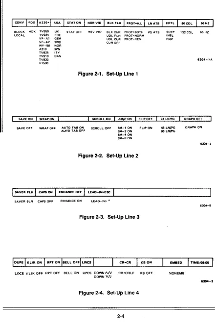
Figure 2-1. Set-Up Line 1
SAVE O~ WRAP ON SCROLL ON JU¥P ON FLIP Off 24 lNfl'G GRAPH OFF
SAVE Off WflAP OFF AUTO TAB ON SCROLL OFF SM-' ON FLIP ON 4B LN/PG GRAPH O~
AUTO TAB OFF SM-2 ON 96 LN/PG
SM-4 ON 8M-B ON
Figure 2-2. Set-Up Line 2
I
s...Vf'fII fLHI
CAPS OH ENHANCE OFFI
LEAD-IN-ESCSAVER BL~ CAPS OFF ENHANCE ON LEAD-IN= ~
63Qol-9
Figure 2-3. Set-Up Line 3
lOCE KLiK OFF RPT OFF BELL ON UPCS OOWNI\N CRooCRLF KB OFF NONEMB
DOWN V/J
HOST XMIT - 9600 19200 38400 ;0
"
'W 1)4 "' ; 0
,00
'"
120U 1800 2400 3600 4800 7200.lUX BAUD 1100
FIElD_ 19200 38400
"
"
,
"
lJ4.5'"
,CO ",c 1100 1800 2400 3600 4800 1200 96()O HEQLRECEIVE - XMIT
1920(,
38400
;0
"
'w
'J4 ~ 150 000
""
1200 1800 2400 3600 4800 1200 9600l i T ' _ 0
B1T8~1
1 BITS
$TI'AOT
BIT B _ 0 STOP 1 PAR OFF NO PARCHK
aiT B 1 STOP 2 PAR ODD
) Blrs PAR EVE;"
Figure 2-5. Set-Up Line 5
ITOP 1
STOP 2
PA" OFF
PAA 000 PAR EVEN
OTAONLV
OTR & XO"l
Figure 2-6. Set-Up Line 6
AUX OFF
AUX ON TPR ON
eNPROT- HEOM ANSWER
BACK-Figure 2-7. Set-Up Line 7
SETIING UP
OTR ONLY
XO"~)\L{ JT" Ilo xC)'.
,·,1
BOIR OFF
BOIR 0111
630"-5
'234567890123456789012J456789012345618901234567890123456789012345678901234567B90
~ECTION
II
2.2.1 Set-Up Line 1
EiWd
CONYFDX
A230+ USA STATON NORVID BLOCK LOCAL HDX TV950 TV924 VP-Al VP-A2 WY-50 A210 TV925 TV910 TV920 Hl500 UK FRE GER SWD NOR SPN lTV DAN STAT OFF REVVID DescriptionSets nature of link between terminal and host computer.
CHAR allows immediate data transmission between
terminal and the host computer; BLOCK allows for text entry and editing before sending data to the host
computer; LOCAL allows for text entry and editing
w~hout transmitting to
host.
Sets method of communication with host. Set to FOX
(full duplex) if host echoes codes received from terminal
back to the terminal. Set to HDX (half duplex) if host does not echo codes
back to
terminal.Sets general operating characteristics of terminal, to
native mode orto an emulation. A230+ Ampex 230 plus TV950 TeleVideo 950 TV924 TeleVideo 924 VP-Al ViewpointAl VP-A2 Viewpoint A2 WY-50 Wyse 50 A210 Ampex 210 TV925 TeleVideo 925 TV910 TeleVideo910 TV920 TeleVideo 920 H1500 Hazehine1500
Sets national character set of keyboard: USA American English UK British English FRE French
GER German
SWD Swedish
NOR Norwegian
SPN Spanish lTV Italian DAN Danish
Sets whether or not to display status line during normal operation.
BLKFLH
PROT.H.I.
LNATB
EDTL
BOCOL
60HZ
BLKCUR UDLFLH UDLCUR CUR OFF
PROT.BOTH PROT.NORM PROT. REV
PGATB
EDTP INSL INSP
132 COL
65HZ
SETTING UP
Sets appearance of cursor.
BLK FLH Flashing block BLK CUR Sleady block
UDL FLH Flashing underline UDL CUR Steady underline CUR OFF Notdisplayed
Sets the video attributes of characters in protected fields:
H.I. BOTH NORM REV
half intensity
reverse video & half -intensity normal
reverse video
Sets scope of affected characters when using embedded video attributes. If LN ATB, characters affected are only those to the end of the line containing the cursor. If PG ATB, characters affected are all those
to the end of the screen.
Sets style and scope ofedhing (see Section III):
EDTL replace characters, to end of line EDTP replace characters, to end of page INTL insert characters, to end of line INTP insert characters, to end of page
Sets number of columns (line length) to
be
displayed. Sets refresh rate of screen. Set to 65 HZ to eliminateSECTION II
2.2.2 Sel-Up Line 2
SAVE ON
WRAP ON
Q1Mr
SAVE OFF
WRAP OFF
Description
Turns on/off CRT Saver. If SAVE ON, CRT Saver is ON.
Then, if terminal is left on but data is not entered for a period of 10 minutes. displayed characters disappear. Pressing a key or receiving data causes previously displayed characters to reappear.
Sets effect of data which exceeds end of a line. If WRAP ON, cursor and subsequenct data wraps around to beginning of next line. If WRAP OFF, cursor remains at end of line and each subsequent character overwrites existing character in last column.
AUTO TAB ON (Only
if
emulation"" TV924) Sets range of linesAUTO TAB OFF accessible by tabbing
SCROLL ON SCROLL OFF
JUMPON SM-10N
SM-20N SM-40N SM-80N
FLIP OFF FLIP ON
24 LN/PG 48 LNlPG
96LNlPG
GRAPH OFF GRAPH ON
AUTOTABON entire screen
AUTO TAB OFF currentlineonly
Sets effect of data which exceeds end of last line of a page. If SCROLL ON. all data moves up one line (on the page) to make room for new data. If SCROLL OFF,
data remains in place; new data overwrites existing data,
beginning at HOME posRion (ofthe page).
Sets method of scrolling data that is received from host. If JUMP ON, data is scrolled on the screen as fast as it is received from the host. If SM-n ON, data is scrolled one line at a time, at -n"lines per secon:!.
Sets -writing location" of data exceeding last line on a page. If FLIP OFF, data is written on the same page. If FLIP ON, data is written on the next page.
Sets number of lines per page; i.e., divides 96-line memory capacity into pages. (lines/page affects, for example, way in which data is stored and scrolls.) Setting detennines total number of pages available:
Setting
24LNlPG 48LNlPG 96LNlPG
HBOcal 4 2 1
It 132 col 2 1
SETIING UP
2.2.3 Set·Up Line 3
SAVERFLH
CAPS ON
.Ql.!Jm: Description
SAVER BLN Sets/indicates appearance of the Set-Up Line when the
CRT Saver comes on. If SAVER FLH, the Set-Up Line
flashes when displayed data disappears; if SAVER BLN,
the Set-Up line does not appear so that the entire screen is blank.
CAPS OFF Sets/indicates the appearance of the CAPS LOCK
indicator H the Status Une is turned off (Line 1). If CAPS ON, "CAPS" appear in the Status Line area whenever the CAPS LOCK is in effect. If CAPS OFF. no indication is given in the Status Line area when CAPS LOCK is in effect.
ENHANCE OFF ENHANCE ON Sets availability of tenninal's native features to an emulation, "enhancing" the emulated terminal's
operation. Set to ENHANCE ON for the added features (programmable function keys, 132 column, graphics characters).
2.2.4 Set-Up Line 4
EimI!
DUPE KLiKON RPTON BEll. OFF LWCS CR.CR KBON EMBED TIME:08-00QIl!ru:
LOCE KLiKOFF RPTOFF BELLON UPCS DOWN AN DOWNA/J CR.CRLF KBOFF NONEMB DescriptionSets whether or not certain edit key codes are transmitted to host. If DUPE, codes are transmitted. If LOCE, codes are not transmitted. Applies only if
terminal is set to CONV and FOX (Line 1).
Sets effect of typing a key. If KLiK ON. electronically synthesized ~clickn accompanies typing a key. If KUK OFF, no sound accompanies typing a key.
S.ts effect of holding down a key. If RPT ON. held key will repeat. If RPT OFF, holding a key is same as typing key once: only one character results. NOTE: The following keys never repeat:
BREAK FUNCT
CAPS LOCK LOC ESC I ESC CLEAR I HOME RESET
CTRL SHIFT
Sets effect of CU/$Or approaching right margin. If BELL ON, bell sounds when cursor reaches column 72 if 80 COL. column 120 W 132 COl.
Sets the effect of pressing an alphabet key at power-up. If UPCS, it produces an upper case character (CAPS appears on the Status Line). If LWCS, it produces a lower--case character.
W errulatlon - TV924) Sets code transmitted by pressing DOWN arrow:
DOWW/J CTRUJ
Sets terminal's response to a typed or received carriage return. If CR-CR, moves cursor to column 1 of the same line; if CR",CRLF, moves cursor to column 1 of the next line.
Used to lock/unlock keyboard. KB OFF locks the keyboard; i.e., prevents data entry via keyboard.
Sets the type of video attributes. If EMBED, a video attribute
is
assigned to a range and occupies a column position. If NONEMB, a video attribute is assigned on character-by-character basis. See Section III for more information.2.2.5 Status Line 5
.EiWl!
Q!W
HOSTXMIT =9600 19200
38400 50 75 110 135 150 300 600 1200 1800 2400 3600 4800 7200
RECEIVE= XMIT 19200
38400 50 75 110 135 150 300 600 1200 1800 2400 3600 4800 7200 9600
BIT 8=0 BIT8=1
7 BITS
STOP 1 STOP 2
PAR OFF PAR ODD
PAR EVEN
NOPARCHK PAR CHECK
DTRONLY XONONLY
DTR&XON NONE
SETTING UP
pescriptjon
Sets the rate (bits/second) of transmitting data from
terminal to host.
Sets the rate (bits/second) of transmitting data from host
by terminal. XMIT sets receive rate to send rate.
Sets the data word configuration (the number of bits when transmitting data between host and terminal) and the contents of Bit 8. 7 BITS means there is no eighth bit.
Sets
the
stop bit configuration.Sets the type of parity applicable to each data word transmitted.
Set PAR CHECK if the terminal requires a parity check for compatibility with host.
Sets
the
transmission protocol:OTR ONLY Data Terminal Ready only
XON ONLY XONIXOFF only
SECTION II
2.2.6 Set-Up Line 6
AUX BAUD=9600
BIT8=0
STOP 1
PAR OFF
DTRONLY
AUXOFF
BDIROFF
19200 38400
50
75 110 135
150
300 600 1200 1800 2400 3600 4800 7200
Description
Sets the rate (bits/second) of transmitting data through the printer
port.
BIT 8 "" 1 Sets the data word configuration (the number of bits
7 BITS when transmitting data between host and terminal) and the contents of Bit 8. 7 BITS means there is no
eighth bit.
STOP 2 Sets the stop bit configuration for sending data to the
printer
port.
PAR ODD Sets the type of parity applicable to each data word
PAR EVEN
transmitted to
the printerport.
OTR & XON Sets the transmission protocol:
~
Protocol
OTR ONLY Data Terminal Ready only
DTR & XON Data Terminal Ready and XON/XOFF
AUX ON Sets the status of the printer
port.
usually where dataTPR ON received from the host is sent:
BDIRON
AUX OFF screen only
AUX ON
screen
and printerport
TPR ON printer port only
NOTE: During execution of page print command, message "PTG~ appears.
2.2.7
Set
Up Lino 7fiWlj
FIELD.FS
ANSWER BACK -X.X.1
SETTING UP
Descriptjon
Sets characters sent in place of protected field, when
protected fields are not transmitted. Type in desired
characters. Any two characters acceptable; default is FS (field separator) :: 1C (hex). NOTE: if mistake made in typing, use Arrow key to leave field. Then return to field
and type in correct characters.
Set to match
host's
~nd 21 line terminator. Type indesired characters. Any two characters acceptable; defau~ is US (unit separator) • 1 F (hex). NOTE:.
mistake made in typing, use Arrow key to leave field. Then retum to field and type in correct characters:
Sets characters sent denoting start of protected field. when protected fields are transmitted. Type in desired
characters. Any
two
characters acceptable; default is E(s)C}. NOTE: 'if mistake made in typing, use Arrow key to leave field. Then return to field and type in correct characters.Sets characters sent denoting end of protected field, when protected fields are transmitted. Type in desired characters. Any two characters acceptable; default is E(s)C (. NOTE: if mistake made in typing, use Arrow key to leave field. Then return to field and type in correct characters.
Set to match host's .and ~ message terminator. Type in desired characters. Any two characters acceptable; default is CTRUM (carriage return). NOTE: if mistake made in typing, use Arrow key to leave field. Then return to field and type in correct characters.
·:11::''''
IIUN II2.2.8 SetUp Line 8
Tab stops are !lQ1 saved when the tenninal is tumed off. Thus, when you first turn on or reset the terminal, there are no tabs set. If you want to use tab stops, you must first set them. Tab stops may be set in any column. Tab stops may be set or cleared in one of two ways, in Set~Up or by using an escape sequence.
10 Set~Up To set a tab stop,
1. Movelhecursorto the desired column.
2. Press the space bar. A NT" appears in the column.
To clear an existing tab stop,
1. Move the cursorlo the appropriate stop.
2. Press the space bar. The "T" disappears from the column .
Using an Escape Sequence
•
Tabs may also be set or cleared during nonnal operation without entering SET~UP.
To set a tab stop
1. Move the cursor to the desired column.
2. Press or execute via the host the sequence ESC 1.
NOTE
If write-protection is ON, this command generates a vertical column of half-intensity spaces, from the rowan which the cursor is positioned down to the first row containing a protected character in the column or to the end of the page, whichever comes first.
To clear an existing tab stop,
1. Move the cursor to the appropriate stop.
2. Pressor execute via the host the sequence ESC 2.
NOTE: If write-protection is ON, this command has no effect.
To clear all tab stops,
1. Enter or execute via the host the sequence ESC 3.
SECTION III
OPERATING AND PROGRAMMING THE TERMINAL
INTRODUCTION
This section explains how to operate and program the Ampex 230 plus terminal using its
native characteristics; i.e., when it is not emulating another terminal. Emulating another
terminal is discussed in Section IV.
3.1' OPERATING MODES
The Ampex 230 plus terminal has basically three "operating modesH
; two of these allow
communication between the terminal and a host computer. The desired operating mode
may be chosen while in Set-Up or by entering the appropriate escape code (see below).
Table 3al. Operating Mode Escape Codes
Operating Mode Escape Code
Conversation
Block
Local
ESC C
ESC B
Table 3-2. Description of Operating Modes
Operating Mode Description
Conversation
Block
Local
Data entered via the keyboard is transmitted immediately to the host. Its appearance on the screen depends on whether or not echoing is in effect (see "Communications Mode" below). Editing command codes are transmitted to the host, interpreted and acted upon, with the results displayed on the screen. Printing may be either executed via the host or initiated from the keyboard.
Data entered via the keyboard is displayed immediately but is not transmitted to the host until a SEND command is given. Editing is "local": editing commands are interpreted and acted upon by the terminal. Printing may be either executed via the host or initiated from the keyboard.
Data entered via the keyboard is displayed immediately and is ~ transmitted to the host. Editing is "on-screen": editing commands are interpreted and acted upon by the terminal.
SECTION III
3.1.1 Communications Mode
Proper display of data on the terminal screen depends in part on the communications setup of the host computer. In particular, host computers mayor may not send back ("echo") for display on the terminal's screen data entered via the keyboard and transmitted to the host. If the host does not echo, then the terminal must transmit both to the host and
to the screen.
Proper display then depends on choosing the right "communication mode" for the terminal.
If the host is set to echo data,
In Set-Up, sellhe duplex to FDX (full duplex), or Enterthe sequence ESC 0 F
If the host is set to not echo data,
In Set-Up, set the duplex to HDX (half duplex), or Enter the sequence ESC 0 H
NOTE: if the host is set to echo and duplex is set to HDX, all characters will display double. If the host is set to not echo and duplex is set to FOX, no characters will be displayed.
Editing and the Commmicatioos Mode
Most of the time (e.g., using a word processing program), editing will be done while in Full Duplex (FOX on Line 1) Conversation (CONV on Line 1).and. Duplex Edit (DUPE on Line 3) mode. In this situation, the editing and cursor-moving keys are transmitted to the host and echoed back to the screen. [NOTE: if an application program cannot interpret the code transmitted by the key, the command will usually be ignored. NOTE also: You can program
a key so that it transmits a code the application can interpret. See ·Programming"]
In some configurations, it may be appropriate to use an alternative to Duplex Editing, Local Editing. In Local Editing, editing is on-screen, the terminal does not transmit codes for the following keys to the host:
Arr"" Keys (Up, Demn, Left, Right)
BACKSPACE ERASE LINE
BACKTAB ERASE PAGE
CLEAR INSERT CHARACTER
DELETE CHARACTER INSERT LINE
DELETE LINE HOME
ENTER CE
PAGE PRINT
SEND TAB
To turn on Local Editing,
in Sel-Up (Line 3). choose LOCE. or enter the sequence ESC k
To turn off Local Editing (return to Duplex Editing),
in Set-Up (Line 3), choose DUPE, or
enter the sequence ESC I (lowercase I).
3.2 DISPLAYING DATA
There are several choices which affect how all data is displayed on the screen.
3.2.1 Video Background
OPERATION
The background
may
be set to either normal (light letters against a dark background) or reverse (dark letters against a light background) video, either by going into Set-Up (Une 1)or by using one of the following sequences
normal
reverse
3.2.2 Video Attributes
Seguence
ESCd ESCb
Set-Up
NORVID REVVID
Each character displayed on the screen has two components: a datum attribute
(essentially, what letter
it
is) and a video component (its appearance on the screen). The video attribute of characters may be changed, either before or after entering the character.In addition to normal (the same as the background), a character may be displayed with any of five attributes:
blank (character not displayed)
flash
reverse (opposite the background) underline
half-intensity (dim)
and with any combination of these: e.g.
---
..
_
...
A particular video attribute or combination is inititated by a three~character escape sequence:
ESC G n
where "n" is the value associated with the attribute or combination. The value of "n" associated with each attribute is given in Table 3~3.
The effect of the sequence depends on whether attributes are embedded or not embedded.
Table 3·3. Video Attribute Escape Sequences
Escape Sequence Attribute normal blank flash blank flash reverse blank reverse ftash reverse blank flash reverse underline
blank underline flash underline blank flash underline reverse underline blank reverse underline ftash reverse underline blank flash reverse underline normal H.1.
blankH.1. flash H.1. blank flash H.1.
reverse H.I. blank reverse H.l. flash reverse H.I. blank flash reverse H.1. underline H.1.
blank underline H.I. flash underline H.I. blank flash underline H.I. reverse underline Hoi. blank reverse underline H.I. flash reverse underline H.I.
ESCG ...
o
1 2 3 4 5 6 7 8 9 < = > ?P
qr
s
t uv
w x yz
{I
}OPERATION
3.2.2.1 Embedded Attributes
If
a
video attribute is embedded, it changes the appearance of alt characters in its "range".Data already in the range Q( data entered into the range appears with the assigned
attribute.
An embedded attribute's range is either the column position· occupied by a different embedded attribute or the "end" (of the current line or current page, depending on the setting in Set-Up, Line 1).
Settina
LNATB PGATB
Range ends at the Line
Page
* An embedded attribute occupies a column and overrides any character previously entered in the column.
To select embedded video attributes,
In Set-Up (Une 3), choose EMBED, or
Enter the sequence ESC. 7
FOR EXAMPLE, if
row
1 reads:Now is the time for an good men to come to the aid of their terminal.
to make "all" flashing,
1. Move the cursor to column 20.
2. Enterthe sequence ESC. 7 (for embedded attributes)
3. Enterthe sequence ESC G 2 (all characters after column 21 begin flashing; the embedded attribute occupies column 20).
4. Move the cursor to column 24.
5. Enterthe sequence ESC G 0 (an characters after column 25 appear normal; the embedded attribute occupies column 24).
3.2.2.2 Non-Embedded Attributes
If a video attribute is non-embedded, each character subsequently entered anywhere on the screen has the asssigned attribute. (Note: a non-embedded attribute does not take
up a column.)
To select non-embedded video attributes,
SECTION III
FOR EXAMPLE, H row 1 reads:
Now is the time for all good men to come to the aid of theirtenninal.
to make "Now" and ~all" flashing,
1. Move the cursor to column 1.
2. Enterthe sequence ESC. 8 (for non embedded attributes)
3. Enter the sequence ESC G 2 (typed characters will appearflashing). 4. Type "Now".
S. Move the cursor to column 21.
7. Type "all".8. Enterthe sequence ESC G 0 (typed characters will appear normal).
Defining a Bange for Non-Embedded Attributes
With the Ampex 230 plus terminal, you can also define a range for non-embedded
attributes. Characters in the range will have the assigned attribute.
To define a range for non-efrbedded attributes, enter the sequence
ESC
.B
,
c
R Cwhere r, C
. R,C
denote the beginning row and column aftha range (see Appendix G) denote the ending row and column of the range (see Appendix G)
NOTE
The particular attrbute assigned to the range is the attribute in effect
when the range is defined. In other words, enter the sequence for the desired attribute.be.mm entering the sequence specifying the range.
FOR EXAMPLE, H rows 1 and 2 'ead:
Now is the time for all good men to come to the aid of their terminal.
to make "all good men to come to" underlined and half-intensity,
1. Enterthe sequence ESC G x (for underline half-intensity).
OPERATION
3.2.2 Displaying All Characters
Usually, only alphabet and numeric characters are displayed when entered. Pressing the
CTRL key, the ESC key, the Backspace key or similar keys enters a code but no character
is displayed. These characters may be displayed however (see Appendix H for a list of the characters and their meaning).
To display but not interpret all characters (sometimes called "monitor mode"), including
escape sequences and control characters, enter one afthe sequences
ESCU CTRU1
To return to the usual display of characters, enter one of the sequences
ESCX CTRU2 ESCu
3.2.3 Double Size Characters
The terminal is capable of displaying characters twice the height and/or twice the width of
standard-size characters.
The basic procedure is
1. Move the cursorto the desired row.
2. Enter the escape sequence for the desired size. Characters already on the row or characters you then type onto the rowwill have the desired size.
A double-high character is formed using two adiacent
rows:
the top haH of the character appears on the higher row, the bottom half appears on the lowerrow.
TOOs, to get the resuUing effect of double-high characters, the same characters must appear twice, once on eachrow.
To enterthe top of the each character.
1. With the cursor on the upper
row,
enter the sequence ESC m 1 2. Type In the desired characters.To enter the bottom half of each character:
1. With the cursor on the lower row, enter the sequence ESC m 2 2. Type in the same characters as above.
To retum to a row of double-high characters to single-high characters,
SECTION III
DQuble-Wide
A double~wide character is formed using adjacent columns on the same line: each letter
fills two columns. NOTE: when you specify double-wide characters for a row, any
characters in the r.iQb1 half of the row are lost.
To enter double-wide characters:
1. With the cursor on the desired row, enter the sequence ESC p 1 2. Type in the desired characters.
To return a row of double-wide characters to single-wide characters,
1. With the cursor on the appropriate
row,
enter the sequence ESC p 0Double High and Wide
A double-high, doubfe-wide character is formed by combining the two approaches above,
using adjacent rows and adjacent columns to form each character. NOTE: when you
specify double-wide characters for a
row,
any characters in the right half of the row are lost.To enter the
top
of the each character:1. With the cursor on the upper row, enter the sequences ESC m 1 ESC P 1 2. Type in the desired characters.
To enterthe bottom half of each character:
1. Wrththecursoronthelowerrow,enterthesequenceESCm 2 ESCp 1 2. Type in the same characters as above.
To return to a row of double~high, double~wide characters to single~high, sing[e~wide
characters,
OPERATION
3.2.4 Special Graphics Characters
The terminal is also capable of generating special line and block graphics characters. In other words, pressing a key will produce not an alphabet or numeric character, but a
graphics character.
To turn on the graphics mode,
in Set-Up (Line 2), choose GRAPH ON; or
enter the sequence ESC $
To'urn off the graphics mode,
in Set-Up (Line 2), choose GRAPH OFF; or enter the sequence ESC %
The graphic generated by each key is given in Figure 3-t.
space
0
0Q
@0
p
0
IJ
p
~
[j
r=
Ar1
Q8
•
~
q~
iJ
2
rJ
Bfa
R(J
bCl
r
C
#
ij
3~
c
fJ
s
G
c
Cj
0C
$
~
4
Ii
D
11
T
8
d~
Ii
%
~
5
II
E
[S
Urs
•
~
"
~
8<
ts
6
ri
Fra
Vra
~
v
rI
~
7
rI
G
@
W@
g
m
.."m
fI
8~
H2J
X
2J
hiI
x
iJ
~
9
~
ill
L1
V
ill
L1
i'!
y
.,
PJ
[I]
[I]
II
IJ
•
!l
J Zz
~
m
Kn
n
kII
{~
+
U
u
8
<S
L
BJ
BJ
!
ii
~
=EI
MrB
rB
m
~
}II
§
n
n
E
II
~
> Nill
ill
n
~
?!
0
ill
ill
0~
DEL
•
U
U
SECTION III
3.3 Scrolling and Flipping
The contents of the terminal's memory (what you enter at the keyboard and data received from the host) are displayed on the screen. The contents of the screen are stored in the
terminal's memory.
"Scrolling" is the process of moving data from one line to an adjacent line (up or down). Data scrolls past the terminal's screen, like a film scrolls through a film projector. Data also
scrolls in memory: as new data is received, existing data is pushed "up" a line. To set the rate at which data scrolls,
in Set·Up (Une 2), choose JUMPONor
SM-n
where n
=-
the rrumberofscanning Hnes per second (1,2,4,8).If scrolling is setta JUMP ON, data scrolls as fast as it is receftted.
3.3.1 Scrolling and Page Size
If there were a one-Io-one match between memory and screen (where each handled 24
lines of data), a line of data which scrolls "oW the screen would als.o scroll "out of" memory.
On the Ampex 230 plus, the screen handles 24 lines of data, but memory handles 96
lines. In this situation, the screen acts as a window into memory (see Figure 3-2).
Screen size matches
memory size saeensize; Memory sIze exceeds
the screen acts as a window into memory
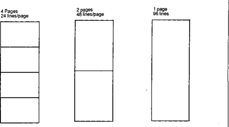
The 96 lines of memory may be set upas 1,2, or 4 pages (see Figure 3-3).
4 Pages 241ines/page
2pa,os
48lineslpage
1 page
[image:42.541.107.494.109.324.2]96 lines
Figure 3-3. Alternative Page Divisions of Memory
OPERATION
Received data scrolls only on the current page, i.e., the page on which the cursor is located. Thus, the size of a-page determines how much new data can be stored before existing data is lost.
The size of a page (and thus the number of pages in memory) depends on two choices: the number of lines per page and the number of columns per line.
Lines/page
24
4896
Page Size (in characters)
SECTION III
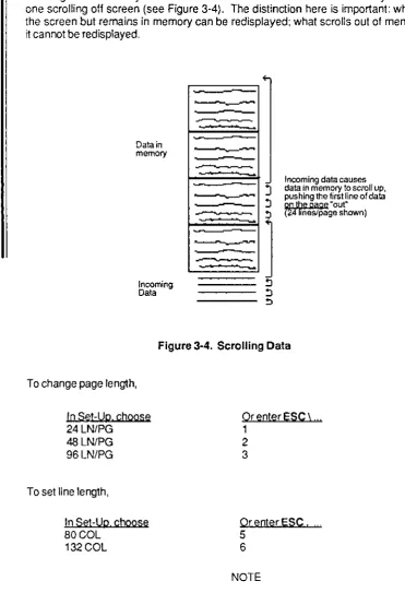
Because the screen is a window, the line of data which scrolls off the screen need not be scrolling out of memory. And the line of data which scrolls out of memory need not be the one scrolling off screen (see Figure 3-4). The distinction here is important: what scrolls off the screen but remains in memory can be redisplayed; what scrolls out of memory is "lost",
it cannot be redisplayed,
Data in
memory
Incoming Data
F-=-=l-"
~
--Incoming data causes
:J
data in memory toscrollup,pushing the first line of data
~ Qll 'be paQe "out"
!l (Z4ifneslpage shown)
, =---
:=
l
!l
[image:43.542.75.447.74.618.2]"
Figure 3-4. Scrolling Data
To change page length,
In Set-Up, choose
24 lN/PG 48 lN/PG 96 lN/PG
To set line length,
In Set-Up. choose
BOGal 132 Gal
Or enter ESC \ ,,' 1
2 3
Or enler ESC! .
5 6
NOTE
=
ii
ii
•
·
•
•
,-,
OPERATION
3.3.2 No Scroll
Scrolling
Un
memory) may be turned Off. If scrolling is off, data exceeding the last tine ofthe page (i.e .• typed data or received data which comes after the entry in the last column of
the last line of the page) OVERWRITES data a/ready on the page, beginning at the HOME
posH ion. (See Figure 3·5.)
Dataln
memO<)'
Incoming dala
-_A"'V"'O
If SCROLL is OFF. data
beyond the last Une ~
!5
1Wr!tesexistingfa Inning at lOW 1,
column of the page.
Figure 3-5. No Scroll
Note: If lines per page is 48 or 96, data will continue to scroll in the djsplay, even if scrolling
is tumed OFF.
Totumoftscrolllng
In Set·Up (Une 2). choose SCROLL OFF
'fscwll is
on
incoming data exceedIng last !joe of page
is stored on last line, preceding data scrolls "up" one line, data on line 1 scrolls ·out" of memory (is lost)
SECTION III
3.3.3 Customizing Scrolling
Ordinarily, the area of the screen in which data scrolls is the entire 24 rows; and the lines of memory in which data scrolls is the current page. For example, if the cursor is on page 2
when lines per page is 48, then the scrolling area of memory is lines 49 through 96.
Scrolling can be customized in two ways. One way, defining a scrolling region, is used to restrict the area of the screen, and the related area in memory, in which data may scroll. The other, locking lines, is used to exclude from scrolling certain rows of the screen, and their associated lines in memory.
NOTE: Customized scrolling applies only to the page on which it is set-up. E.g., if you customize scrolling on page 1, page 2 may scroll in the usual way.
NOTE also: When scrolling is customized, cursor addressing is relative to the customized area. For example, if a scrolling region has only 10 lines, the last line of the region is the tenth line.
NOTE therefore
Customizing scrolling when the lines/page is 48 or 96 is NOT recommended.
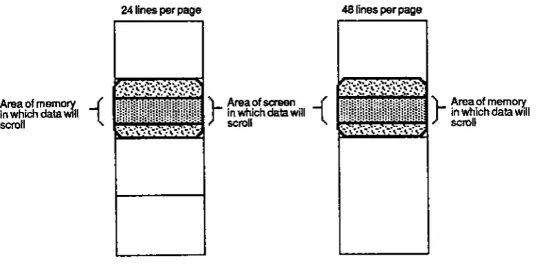
3.3.3.1 Defining a Scrolling Region
Defining a scrolling region simukaneously restricts scrolling
to a particular area of the screen to a particular area of memory.
Any block of adjacent rows of the screen may be defined as the scrolling region. The associated lines in memory, Le., the lines appearing in those rows when you define the region, determine the scrolling region of memory. In effect, it determines what lines of memory outside the scrolling region remain visible. (See Figures 3-6.)
To define a scrolling region, enter the sequence
ESC
where A
B
A B
top row of the screen scroll region (in ASCII) (see Appendix G) bottom row of the screen scroll region. (in ASCII) (see Appendix G)
To reset scrolling to the full screen and the entire page, enter the sequence
OPERATION
NOTE
If lines per page is 24, the row number is the same as the line number
(cursor location). In all other instances, it is necessary to count in order
to determine the (decimal) number of a row.
NOTE further
Once a scrolling region is defined, cursor location is determined by the
scroll region. E.g., the first line of the scroll region is identified as line 1,
the second tine (if any) as line 2. and so on.
NOTE finally
Data exceeding the last line of the scrolling region pushes all
preceeding lines of the region up one, so that the first line of data in the region is
lost.
Example:
Suppose that lines/page is 24.
To define a scrolling region of rows 10 through 15. enter the sequence
ESC
Received or typed data scrolls only on those rows. The first row of the region, row 10, is
identified as line 1 on the Status line, row 11 as line 2, and so on up to row 15 as line 6. In this situation, the cursor cannot go beyond line 6.
When the entire screen again becomes the scrolling region, the data appearing on rows 10 through 15 scroll inthe usual way.
Area of memory { In which data WIll
""""
24 lines per page
)-A .... inwhichdatawill of"""'" {
scroll
[image:46.549.89.480.447.640.2]48 lines per page
Figure 3-6. Scrolling Region
)
-Area of memo~
inMllchdatawll1
SECTION III
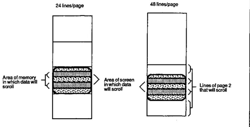
3.3.3.2 Locking Lines
Locking a line simultaneously excludes from scrolling
the rowan the screen on which the cursor appears
the associated line in memory on which the cursor is located.
Any collection of rows may be locked; up to a total of 23. The associated line(s) in memory, i.e., the line on the row when the row is locked, is excluded from scrolling. In other words, the lines in locked rows remain on the screen when the page is on screen. All other lines
of the page scroll. Together, the effect is like a
window
with louvers. (See Figures 3-7.)To lock a line,
1. Move the cursor to the row to be locked
2. Enterthe sequence ESC! 1
3. Repeat steps 1 and 2 for each row to be locked.
To unlock all locked lines. enter the sequence
ESC
2NOTE
When lines arB locked, cursor location is determined by the scroll area.
E.g., the
first
line of the scroll area is identified as line 1. the second line (if any) as line 2. and so on. The number of the last line of the scroll area isPage size· number of locked lines
NOTE also
24lines/page 48 lines/page
Area of memorY. - (
in which dais Wilt
sC70lI .
Example:
Suppose that Lines/page
Is
24.To lock rows 10, 15, 19,ond20,
Area 01 screen in which data
[image:48.534.73.488.91.302.2]will scroll
Figure 3-7. Locking Lines
roove the cursor to row 10 and enter the sequence ESC I 1
move the cursor to each of the other rows and enter the sequence
OPERATION
Unesol~2
that will scrOll
In this situation, lines 10,15,19, and 20 are locked, i.e., excluded from scrolling. Only the unlocked lines scroll. The first unlocked line of the page, in this case line 1, is identified
on the Status Line as line 1, the second unlocked line as line 2, and so on. Line 10 on the Status Line is the data on line 11 in memory (the data on line 10 in memory is lock