(ALtm]
COMPUTER SYSTEMSComputer System
ACS8600
User Manual
Revision B March 22, 1982
DI6CLAIMER
THIS IS A PRELIMINARY PUBLICATION OF THE ALTOS ACS8600 COMPUTER SYSTEM DOCUMENTATION AND IS PRE-SENTED FOR INFORMATION PURPOSES ONLY; IT WILL BE CHANGED WITHOUT NOTICE.
THE INFORMATION CONTAINED HEREIN REPRESENTS THE MOST CURRENT INFORMATION AVAILABLE AT THE TIME OF PRINTING, HOWEVER, THE INFORMATION HAS NOT BEEN THROUGHL Y REVIEWED NOR HAS IT BEEN APPROVED IN ITS PRESENT FORM. ALTOS COMPUTER SYSTEMS ASSUMES NO LIABILITY WHATEVER RELATED TO USE OF INFORMATION PRESENTED IN THIS PUBLICATION.
PRELIMINARY 86SS OSER MAROAL FRONT MA'l'TER
FEDERAL COMMUNICATIONS COMMISSION NOTICE
WARNING
This equipment generates, uses and can radiate radio frequency energy and, if not installed and used in accordance with the instructions manual, may cause interference to radio com.unications. It has been tested and found to co.ply with the limits for a_Class A co.puting device pursuant to Subpart J of Part 15 of FCC Rules, which are designed to provide reasonable protection against such interference when operated in a co.mercia1 environ.ent. Operation of this equipment in a residential area is likely to cause interference in which case the user, at his on ezpense, will be required to take whatever measures may be required to correct the interference.
PRELIMIRARY 86BB USER MAlIUAL
[AlIIm)
COMPUTER SYSTEMSPRE LIM I N A R Y
ACS 861. COMPftER SYSTEM USER MAllUAL
REVISION B
MARCH 22, 1982
DISCLAIMER
FRO~ MATTER
THIS IS A PR8LIMIDRY PUBLICATION OF mE ALTOS ACS 861. COMPUTER SYSTEM DOCUMENTATION ABD IS PRESENTED FOR INFORMATION PURPOSES ONLY1 IT WILL BE CHARGED WITBOur NOTICE.
THE INFORMATION CONTAINED HEREIN RBPRESRmS THE MOST CURRElft' IllIFORIlATION AVAILABLE AT THE TIRE OF PRINTING, HOWEVER, "l'BE IlI!FORMATION BAS NOT BEEN THOROUGHLY REVIEWED NOR HAS IT BEEN APPROVED Ill! ITS PRESENT FORM. ALTOS COMPUTER SYSTEBS ASSUMES NO LIABILITY WHATEVER RELATED TO USE OF IlI!FORMATION PRESENTED IN ~IS PUBLICATION.
Manual Part Number: 690-11392
PRELIKDlARY 861111 USER IlAllUAL COlftBIftS
CONTENTS
SECTION 1. INTRODUCTION
GENERAL INFORMATION •••••••••••••••••••••••••••••••••••••••• ACS 8600 COMPUTER SYSTEM PUBLICATION ORGANIZATION •••••••••• Forms Accompanying this Manual • • • • • • • • • • • • • • • • • • • • • • • • • •
COVER LETTER •••••••••••••••••••••••••••••••••••••••••
CHECKOFF SHEET ••••••••••••••••••••••• ~ ••••••••••••••• W.AR.RANTY CARD •••••••••••••••••••••••••••••••••••••••• QUAL ITY CONTROL REPORTS •••••••••••••••••••••••••••••• System Checkoff Sheet ••••••••••••••••••••••••••••• System Checkout Sheet ••••••••••••••••••••••••••••• Burn-In Summary Sheet ••••••••••••••••••••••••••••• Quality Control Inspection Sheet •••••••••••••••••• Basic User Manual Description ••••••••••••••••••••••••••• SCOPE AND PURPOSE •••••••••••••••••••••••••••••••••••• ORGANIZATION ••••••••••••••••••••••••••••••••••••••••• INSTRUCTIONS FOR USING THIS MANUAL • • • • • • • • • • • • • • • • • • • • • • • • • Manual Supplement Descriptions •••••••••••••••••••••••••• GENERAL SYSTEM DESCRIPTION ••••••••••••••••••••••••••••••••• System Functional Description •••• ~ •••••••••••••••••••••• PRIMARY SYSTEM ENCLOSURE - PHYSICAL DETAILS •••••••••• Size ••••••••••••••••••••••••••••••••••••••••••••••
Weight ••••••••••••••••••••••••••••••••••••••••••••
Front Panel Controls •••••••••••••••••••••••••••••• Rear Panel Connectors ••••••••••••••••••••••••••••• SECONDARY SYSTEM ENCLOSURE - PHYSICAL DETAILS •••••••• Size •••••••••••••••••••••••••••••••••••••••••••••• weight
. . .
. . .
.
.
.
. . .
.
Front Panel Controls • • • • • • • • • • • • • • • • • • • • • • • • • • • • • • Rear Panel Connectors •••••••••••••••••••••••••••••• • • • • • • • • • • • • • • • • • • • • • • • • • • •
FEATURES AND CAPABILITIES
SYSTEM CONFIGURATIONS • • • • • • • • • • • • • • • • • • • • • • • • • • • • • • • • Hardware Functional Description ••••••••••••••••••••••••• CENTRAL PROCESSING UNIT •••••••••••••••••••••••••••••• SYSTEM MEMORY •••••••••••••••••••••••••••••••••••••••• MEMORY CONTROLLER •••••••••••••••••••••••••••••••••••• RANDOM ACCESS MEMORY (RAM) • • • • • • • • • • • • • • • • • • • • • • • • • • • MEMORY MANAGEMENT •••••••••••••••••••••••••••••••••••• EXTENDED MEMORY MANAGEMENT ••••••••••••••••••••••••••• PAGES IN MEMORy •••••••••••••••••••••••••••••••••••••• ERASABLE-PROGRAMMABLE-READ-ONLY-MEMORY (EPROM) ••••••• FLOPPY DISK CONTROLLER ••••••••••••••••••••••••••••••• HARD DISK CONTROLLER ••••••••••••••••••••••••••••••••• PARALLEL INTERFACE ••••••••••••••••••••••••••••••••••• SERIAL CHANNELS •••••••••••••••••••••••••••••••••••••• INTELLIGENT SERIAL CONCENTRATOR •••••••••••••••••••••• MAGNETIC TAPE UNIT DRIVE CONTROLLER •••••••••••••••••• MULTIBUS CARD CAGE •••••••••••••••••••••••••••••••••••
CONVENTIONS ••••••••••••••••••••••••••••••••••••••••••••••••
Revision B. March 22, 1982 PILB: 119~5 3/19/82 ToC-1
PRELIIIIlIARY 8688 OSER IIAIIOAL COftBII'lS
CONTENTS
SECTION 1. INTRODUCTION (continued)
TERMS AND ABBREVIATIONS • • • • • • • • • • • • • • • • • • • • • • • • • • • • • • • • • • • • RELATED MANUALS •••••••••••••••••••••••••••••••••••••••••
SECTION 2. UNPACKING AND SETTING UP ~HE COMPUTER SYSTEM
1-21 1-21
GENERAL INFORMATION •••••••••••••••••••••••••••••••••••••••• 2-1 SELECTING A COMPUTER SITE •••••••••••••••••••••••••••••••••• 2-1 UNPACKING THE SHIPPING CONTAINER ••••••••••••••••••••••••••• 2-2 UNLOCKING THE HARD DISK DRIVES ••••••••••••••••••••••••••••• 2-3 Removing the Bottom Cover Plate ••••••••••••••••••••••• 2-3 Unlocking the lB-Mbyte Hard Disk Drive •••••••••••••••• 2-4 Unlocking the 2B-Mbyte or 4B-Mbyte Hard Disk Drive •••• 2-5 SYSTEM CONFIGURATION ••••••••••••••••••••••••••••••••••••••• 2-7 CONNECTING PERIPHERAL EQUIPMENT •••••••••••••••••••••••••••• 2-8 Console Terminal •••••••••••••••••••••••••••••••••••••• 2-8 CONNECTING THE POWER SOURCE TO THE COMPUTER •••••••••••••••• 2-9
Section 3. RUNNING THE ALTOS DIGNOSTIC EXECUTIVE (ADX) PROGRAM GENERAL INFORMATION •••••••••••••••••••••••••••••••••••••••• 3-1
Section 4. INSTALLING THE OPERATING SYSTEM
GENERAL INFORMAT ION •••••••••••••••••••••••••••••••••••••••• 4-1 CP/M-86 SINGLE USER OPERATING SYSTEM ••••••••••••••••••••••• 4-2 MP/M-86 MULTI-USER OPERATING SYSTEM •••••••••••••••••••••••• 4-2 OASIS OPERATING SYSTEM ••••••••••••••••••••••••••••••••••••• 4-3 XENIX (UNIX - VERSION 7) ••••••••••••••••••••••••••••••••••• 4-3 PROGRAMMING LANGUAGES •••••••••••.••••••••••••••••••••••••••• 4-3 APPLICATION PROGRAMS ••••••••••••••••••••••••••••••••••••••• 4-3
Section 5. ALTOS UTILITY PROGRAMS .
GENERAL INFORMATION •••••••••••••••••••••••••••••••••••••••• 5-1
Section 6. UPGRADE KITS AND ADD KITS
GENERAL INFORMATION ••••••••••••••••••••••••• •.• • • • • • • • • • • • • • 6-1
PRELllllRARY 86"" USER IlAllUAL COftEftS
CONTENTS
Section 7. HARDWARE OPERATING SPECIFICATIONS GENERAL
Appendix Appendix Appendix
Appendix Appendix Appendix Appendix Glossary Index
INFORMATION •••••••••••••••••••••••••••••••••••••••• 5-1
NOTE
The ACS System Specification has been coapletely reprinted as Section 7 of this manual. The Specification contains its own Table of Contents, List of Figures and List of Tables (see Section 7)
APPENDICES
A. SHIPPING DAMAGE AND REPAIR PROCEDURES ••••••••• A-I
-B. TROUBLE-SHOOTING PROCEDURES ••••••••••••••••••• B-1 C. COMMON CRT TERMINAL AND PRINTER INTERFACE
CONFIGURATIONS •••••••••••••••••••••••••••••••• C-l D. INSTRUCTIONS FOR PINNING CIRCUIT BOARDS ••••••• D-l E. MATRIX MAPS ••••••••••••••••••••••••••••••••••• E-l F. SCHEMATIC DIAGRAMS •••••••••••••••••••••••••••• F-l G. PREVENTIVE MAINTENANCE PROCEDURES ••••••••••••• G-l
Customer Response Sheet
PRBLIIiDlARY 868. OSER IIAIIOAL
FIGURES
1-1. ACS 8688 Computer System - Publications Organization
Illustration ••••••••••••••••••••••••••••••••••••••••• 1-3 1-2. Forms Accompanying This Manual ••••••••••••••••••••••• 1-4 1-3. ACS 8688 Computer System
- Hard Disk/Floppy Disk Version ••••••••••••••••••••• 1-11 1-4. ACS 8688 Computer System
- Bard Disk /Magnetic Tape Unit Version ••••••••••••• 1-11 1-5. ACS 8688 Computer System Architecture
2-1. 2-2. 2-3.
- Block Diagram ••••••••••••••••••••••••••••••••••••• 1-16 Unlocking the l8-Mbyte Bard Disk •••••••••••••••••••••
Unlocking the 28-, or 48-Mbyte Bard Disk ••••••••••••• ACS 8688 Computer System - Rear-Panel ••••••••••••••••
TABLES
2-5 2-6 2-11
1-1. ACS' 8688 - Mode1/St.orage Media Reference Table ••••••• 1-14 1-2. Add Kit/ Storage Media Reference Table ••••••••••••••• 1-14 6-1. ACS 8688 - Model/Storage Media Reference Table ••••••• 6-1 6-2. Add Kit/ Storage Media Refe~enc~ Table ••••••••••••••• 6-2
PRELIIIIlIARY 86"" USER IlAllUAL SECTION 1. r.T.RODUCTION
ALTOS ACS 86'" COIlPUTER SYSTEM USER IlAllUAL
SBCrION 1. Ilft'RODUCTION
GENERAL DlPOlUIATION
This section describes the structure of the basic User Manual and its supplements (see Figure 1-1), instructions for using the basic manual, and ~ general description of the system.
ACS 86'" COMPUTER SYS~ PUBLICATION ORGANIZATION
Altos Computer Systems has designed a publication structure that differs from most user manuals. The purpose of this structure is fourfold:
(1) To provide accurate system information to the user as quickly as possible.
(2) To permit updating of more dynamic areas of information as design improvements and system enhancements are achieved.
(3) To isolate and identify information blocks so that referencing time is minimized.
(4) To present information in a general-to-specific manner, thus meeting the needs of beginning users as well as more experienced users.
PRBLIIIIIlARY 8611 USER IIAlIUAL SBCrIOR 1. ~ODUC~IOR
The publications you receive with the computer are divided Into three groups (see Figure 1-1):
1. Column 1 of Figure 1-1 illustrates the forms that accompany the manual, and the Basic User Manual sections and appendices which contain rela ti vely unchanging information pertaining to all models in the series.
2. Column 2 illustrates Altos Supplements 3, 4, 5 and 6, which contain more dynamic information pertaining to executing diagnostic programs, installing operating systems, using Altos utilitiy programs, and installing upgrade and add kits. The supplements are designed to be inserted into the User Manual after the shipping container is unpacked.
3. Column 3 illustrates Supporting Manuals, which include pre-printed manuals produced by developers of related software products that operate on the ACS 8699 Computer System. This group may also include more informal technical notes related to such systems, thus insuring that you have the most current' information possible.
Porms Acca.panying this Ranua~
The following forms accompany this. manual. They are valuable records and are provided separately so that they may be taken from the manual and stored in a secure place where they will be available if repairs happen to be needed.
COVER LETTER (info to come) CHECKOFF SHEET
(info to come) WARRANTY CARD
(info to come)
QUALITY CONTROL REPORTS (Info to come)
System Checkoff Sheet (info to come)
System Checkout Sheet (info to come)
Burn-In Summary Sheet (info to come)
Quality Control Inspection Sheet (info to come)
PRELIMIBARY 861111 USER MAllUAL SECTION 1. IRTRODUCTION til
I
I
-
-!
..
i
=
i
...
!..
=
..
..
J 111Q til
•
•
-! !
..
=
~ uI
..
~
;.
•
::10 ~
•
.,
;fI I; :>t
..
•
•
!;I
.'
0'..
-.
~
j
a
til
..
...
VI:a ~
..
=
;. ,~ ;f I '..
,..----r
I ----~
I
I
...---I I
I I
1.. ...
I
~
I
,!~
...
I
-.
...
I ~ _e"
..
i - =¥
~ =~
-,..---'
I .. ~----~
I :
r---
b . . .~ I I I I I
...
'Lo-i
N
!
r .. ~~~-=:===
..
,....-..,
• I . •
I I I
I I
I '.
I I I"~
-.-il
Figure l-l.ACS 86~~ Computer Syste~
Organization Illustration
r-:"_-_-:::z... '
1 • r-... -~...,
: I I __ ----~--~
I I I • • I ' . • I I ! ~i,:
~ If~~-=
....
.-...
-•
...
-....
:
-•
-• 0
.. ..
.IIL.!.
..
... •.
...
-
..
~
a.:
--Publications
Revision B. March 22,1982 FILE: ID1TR01 3/19/81 1-3
.,.-..-,
~--.=..I ~~-:::.----..., I • I
• I I
I I I I I,
I I I • I.~ ....
[image:13.618.81.607.55.660.2]PRBLIIiIDRY 8688 OSER IIAIIOAL SECTION 1. ~ODO~ION
.. :
,I
.
~() A
l..
I
r
"If£:2C!.
.LvsP~:T''',o
a~PD2.r
S
(J rt...ftj-fA)
£JU
M.M11~iSkee+
S'
Y~7'e
lit
Chd4JUT
'S
n."e.e-r"
~ 'r~.
rENt
Cltte.d
IJFr
SVt
Qe:1:..
~'AJT~L
~e.poi2.T~
: ,,
--- ... , .. -
--
.WA"-iA
IJT~I
C!P\RD
,·C.he.C.t~F~ ~L,eeT
~ I·~
I!
I
C.O"E.\<-il
Le:-
Ti
f!..
It.
IIi
I
!j" " I
Ii
III
II
i
I
'I
i /
I
I
!Figure 1-2. Forms Accompanying This Manual
Revision B. March 22,1982 PILB: lIRTR07 3/19/81 1-4
"
[image:14.621.62.560.66.668.2]PRBLIIIIlIARY 8688 USER IIAIIOAL SBCrION 1. ~ODUC~ION
Basic User Manual Description
SCOPE AND PURPOSE
This basic User Manual presents sufficient information so that any user, whether familiar with microcomputers or not, can become familiar with the ACS 8600 Computer syst"em, its component parts, features, capabilities, architecture, and system operation. The manual either presents the information in itself, or provides easily-found references to other publications in which such information can be found.
The manual instructs the user in all required operations from unpacking the shipping container through installing the Operating System and preparing the system to perform the jobs for which the system was purchased.
ORGANIZATION
This User Manual is divided into seven sections, seven appendices, a glossary, an index, and a Customer Response Sheet.
This section, INTRODUCTION introduces you to the basic User Manual itself, and instructs you in its use. It also introduces the manual supplements and other rela ted publica tions, and introduces the ACS 8600 Computer System, including its features, capabili ties, configurations, and component parts (both hardware and software).
Section 2. SETTING UP THE COMPUTER SYSTEM provides instructions for removing the computer and its components from the shipping container, identifying the components, storing related important papers, and physically assembling the system by following step-by-step instructionL This section instructs you in preparing the system for executing the Altos Diagnostic Executive (APX) Program.
Section 3. THE ALTOS DIAGNOSTIC EXECUTIVE (ADX) PROGRAM introduces Supplement 3. EXECUTING THE ALTOS DIAGNOSTIC EXECUTIVE (ADX) PROGRAM which, in turn, provides step-by-step instructions for executing diagnostic programs under supervision of the diagnostic executive to verify operation of the system and its components. ADX prepares the computer system for installation of the selected Operating System.
Section 4. OPERATING SYSTEMS provides information related to operating systems in general, and introduces one or more versions of Supplement 4, which, in turn, provide specific, step-by-step installation procedures for particular operating systems. One or more of the Operating System Supplements will be provided with the system. Each Supplement 4. contains all the information necessary to install the selected operating system after the diagnostic programs have been successfully executed.
PRBLIIIIJIARY 8611 USER IIAIIOAL SBCTIOR 1. ~ODUCTIOR
only the Opera ting Sy stem Supplement r ela ted to the Operating Syst,em(s) purchased (CP/M-86, MP/M-86, OASIS-16, or XENIX) is provided with the system.
Section 4. also introduces you to the supporting manuals and other publications related to the subject operating system.
-Section 5 • ALTOS UTILITY PROGRAMS provides general information related to utility programs and introduces you to SUPPLEMENT 5. ALTOS UTILITY PROGRAMS - USER INSTRUCT IONS which describes Altos Utility Programs available for use with the system, and instructs you in their use.
Section 6. ADD KITS AND UPGRADE KITS provides general information regarding kits available for increasing system capabilities. This section introduces Supplement 6. UPGRADE KITS AND ADD KITS - INSTALLATION PROCEDURES. Purchasers of Add Kits and Upgrade Kits receive simply written installation procedures written specifically for those kits.
Section 7. HARDWARE OPERATING SPECIFICATIONS spec if ically and extensively describes system architecture and functional opera tion, including port assignments, controllers, interfaces, buffer use, and memory management.
Appendix A. ALTOS WARRANTY DESC&IPTION AND SHIPPING DAMAGE REPAIR PROCEDURES describe the Altos Warranty and provide
instructions for filing the End-User Registration Card and the Dealer Registration Card. Instructions are also provided for inspecting for shipping damage, and obtaining repairs and/or service if such damage occurs. This appendix also br iefly describes Altos factory repair and shipping procedures.
Appendix B. TROUBLE SHOOTING PROCEDURES provides basic instructions for isolating and correcting troublesome conditions and determining whether or not a true malfunction actually exists.
Appendix C. COMMON CRT TERMINAL AND PRINTER INTERFACE CONFIGURATIONS provides instructions for connecting and setting most-commonly-used terminals and printers.
I
Appendix D. INSTRUCTIONS FOR PINNING PRINTED CIRCUIT BOARDS (PCB) provides instructions for setting pinning blocks on the various circuit boards to achieve the operating configuration desired.
Appendix F. 'MATRIX MAPS includes all matrix maps in the form current at time the current revision of the manual is printed.
(Early revisions may not have this appendix.)
Appendix G. SCHEMATIC DIAGRAMS includes all schema tic diagrams in the form current at the time the current revision of the manual is printed. (Early revisions may not have this appendix. )
PRELIMDlARY 8688 USER IlABUAL SECTION 1. IlftRODUCTION
GLOSSARY contains definitions of terms used in the manual that may be unfamilia~ to the user. (Early revisions may not have a Glossary.)
INDEX is designed to assist you in referencing desired information. (Early revisions may not have an Index.)
CUSTOMER RESPONSE FORM is a pre-printed form provided to facilitate forwarding of comments and requests to Altos Computer Systems.
INSTRUCTIONS FOR USrBG THIS MABUAL
This manual (and its supplements) guides you through the complete installation process for the computer system from unpacking the shipping container through calling in and executing application programs.
To use this manual most effectively, perform the following steps: 1. Read Section 1 to become familiar with the publications
structure and the system design.
2. Refer to Section 2 and follow the instructions for unpacking the system and_physically connecting the system components.
3. Assemble the publications and verify that all are present. When the shipping container is unpacked, insert the supplements into their proper place in the manual.
3. Refer to Section 3 for general information regarding Altos Diagnostic Executive (ADX) program.
Follow the instructions in Supplement 3 to configure the system, execute the diagnostic programs, and initialize the system. The diagnostic progr ams verify correct operation of the system and its components. Supplement 3 also instructs you in making backup copies of the diagnostic program and operating system diskettes as required.
5. Refer to Section 4 for information regarding operating systems in general and to the applicable Supplement 4. Refer to Supplement 4 for information regarding the specific operating system to be used. This section tells you how to install that operating system and how to load and execute application programs.
One of four Operating Systems w i l l be installed. Each of these systems has its own loading procedures and operating characteristics. Some operating systems also
PRELIRIlIARY 86"" USER MAlIUAL SECTION 1. nrmODUCTION
have their own set of diagnostic programs.
6. Refer to Section 5. for information regarding available Altos utility Programs developed for the system.
Supplement 5 provides specific information regarding individual utility programs.
7. Refer to Section 6. for information regarding increasing system capabili ties through the use of Add Kits and Upgrade Kits.
Supplement 6 provides specific procedures for installing individual Upgrade Kits or Add Kits.
8. Refer to Section 7 and the appendices for more specific information regarding the specifics of system operation. The setup procedure (described in Section 2, and diagnostic procedures (described in Section 3) are generally similar for all ACS 8699 computer models. They will vary somewhat, depending upon the configuration of the model and the peripherals included with the system.
Kanoal Soppleaent Descriptions
A description of SUPPLEMENT 3. EXECUTING THE DIGNOSTIC EXECUTIVE (ADX) PROGRAM is provided in Section 3.
A description of four Operating System Supplements ( Control Program Monitor - CP/M-86, Multi~Program Monitor - MP/M-86, XENIX, and OASIS-16 Operating Sy_stems is provided in Section 4. OPERATING SYSTEMS. This section also provides a descr iption of supporting publications.
A description of SUPPLEMENT 5. ALTOS UTILITY PROGRAMS - USER INSTRUCTIONS is provided in Sect.ion 5.
A descr ipti on of SUPPLEMENT 6. UPGRADE KI TS AND ADD KITS -INSTALLATION PROCEDURES is provided in Section 6.
GENERAL SYSTEM DESCRIPTION
The Altos ACS 8699 Computer System is a multi-user system designed to fit many commercial, technical, industrial, scienti f ic, and educa tional applica tions, as well as many personal, home-computer applications.
This system is designed to perform larger, more complex tasks for more users than other microprocessors. Larger word size allows the use of more powerful instructions and direct addreSSing of more memory. The system requires fewer instructions and fewer computer cycles to accomplish the same job. It can handle complex' rna thema tical problems, larger da ta
PRBLIIIIJIARY 86.. OSER IIAIIOAL S~IOR 1. IlI'.mODUC'lIO!l
base searches and other demanding applications in far less time. More powerful processing capability, larger memory, and special memory man~gement techniques extend multi-user capabilities and allows multi-tasking without long waits for service.
Al though the ACS 8600 Computer System is particularly designed to meet mul ti-user and mul ti-tasking requirements, i t may also be configured as a powerful single-user system. The enhanced computing power of the system is achieved not only through the use of the Intel 8086 sixteen-bit microprocessor chip technology, but also through the use of a separate Intel 8089 Direct Memory Addressing (DMA) I/O processsor, and a unique hardware memory management scheme that greatly increases efficient use of main memory.
The Central Processing Unit (CPU) is the proven 8086 16-bit HMOS microprocessor. It operates at a fast 5 Mhz and can address I-Mbyte of memory. The CPU uses assembly language compa tible with the 8080 and 8085 processors, and performs 8- and 16-bit signed and unsigned arithmetic functions in binary or decimal, including multiplication and division operations.
The ACS 8600 family uses more than one processor. While the 8086 serves as the master CPU, other-processors are dedicated to special tasks. For example, a second processor, one 8089 DMA, handles direct memory accessing for I/O processing. The optional mathematical processor (8087 Floating Point Processor) handles mathematical functions. Although each processor is optimized for its own special task, they all wor k toge ther to shar e the workload for faster execution and decreased response time.
While many mid-sized minicomputer memories lack Error Correction Code (ECC), the ACS 8600 improves operational reliability with its own ECC. The memory has full error detection for single-bit and double-bit errors, and automatic correction of single-bit errors, thus reducing system errors and increasing the already-high system dependability.
The design of the ACS 8600 family of computers includes 500,000 bytes (500-Kbytes) of random access main memory. Main memory is expandable to one- million bytes (l-Mbyte) with full error detection and correction. It also includes I/O controllers for supporting a variety of peripherals such as an additional hard disk, CRT terminals, printers, magnetic tape units and floppy disk uni ts. Full communica tions suppor t, including asynchronous, bisynchronous and networking capabilities are also provided.
ACS 8600 proprietary memory management system assigns a logical-to-physical address translation and various attributes to each 4-Kbyte block of memory so that the non-contiguous physical memory can be assigned to any given task. This capability reduces the need for swapping users or tasks out to disk. The result is
PRELIMINARY 8611 USER IlAllUAL SECTION 1. IRTRODOCTION
that data base sorting, and other tasks requiring large memory are performed faster. The system also provides write and access protection to increase reliability and performance.
Altos Computer Systems supports and distributes four of the most popular operating systems, Control Program Monitor (CP/M-86), Multiple Program Monitor (MP/M-(CP/M-86), OASIS-16, and XENIX
(UNIX, Version 7). More than 300,000 current users of CP/M, MP/M and OASIS can easily upgrade their systems to the ACS 8600 Computer System knowing that their application software is compatible with the ACS 8600 computer.
BASIC, COBOL, PASCAL, and FORTRAN languages are also distributed and supported by Altos Computer Systems.
Although Altos does not generally distribute application program packages, i t does provide a l i s t of such compatible program packages, developed by leading software houses, on request.
Syste. Functional Description
The ACS8600 Computer System is an advanced-design, 16-bit, general-purpose computer manufactured by Altos Computer Systems. System design supports up to I-Mbyte of Random Access Memory (RAM) with full error detection and correction, and a wide variety of mass storage peripherals. Unique memory management hardware increases efficiency of main memory use. The system can be easily extended to meet the requirements of a wide variety of applications.
The ACS 8600 System is based on the Intel 8086 microprocessor family. While the system is primarily designed to meet multi-user and multi-tasking requirements it may easily be configured for large single-user applications. The following list summarizes the main features and capabilities:
PRIMARY SYSTEM ENCLOSURE - PHYSICAL DETAILS Size
19 inches wide, 23 inches deep, 7 inches high Weight
Free-standing weight - 60 pounds Shipping weight - 80 pounds
Front Panel Controls
AC ON/OFF Switch (upper right hand corner) RESET Switch (to left of ON/OFF switch)
PRELIIIIJlARY 8688 USER IIAlmAL
1IIUI/S.'
SE'Fer .
I.OI~.c..
SECTIO. 1. IRTRODUCTION
SYSTCU K8ET
61II1D~
swrt~
Figure 1-3. ACS 8600 Computer System - Hard Disk/Floppy Disk Version
Figure 1-4.
-'
-ACS 8600 Computer System - Hard Disk/Magnetic Tape Unit Version
[image:21.615.55.550.76.695.2]PRBLIIlIIlARY 86.. USER IWIUAL SBC'lIOR 1. DI'lRODOaIOR
Rear Panel Connectors (see Figure 2-3) AC Power Receptacle
Fuse Holder
Parallel Port Interface Connector (DB 37)
Hard Disk Expansion Connectors (29 pin and 59 pin) Console Terminal RS-232-C Connector (DB 25)
Multibus Expansion Interface Connectors (72 pins) Magnetic Tape Unit Expansion Connector (58 pin) Serial 'Port Connectors (1-through-8)
(Refer to Section 7 for specifications.)
SECONDARY SYSTEM ENCLOSURE - PHYSICAL DETAILS Size
19 inches wide, 23 inches deep, 7 inches high weight
Free-standing weight - 55 pounds Shipping weight - 75 pounds
Front Panel Controls
AC ON/OFF Switch (upper right hand corner) RESET Switch (to left of ON/OFF switch) Rear Panel Connectors (see Figure 2-3)
AC Power Receptacle Fuse Holder
Parallel Port Interface Connector (DB 37)
Hard Disk Expansion Connectors (29 pin and 58 pin) Console Terminal RS-232-C Connector (DB 25)
Multibus Expansion Interface Connectors (72 pins) Magnetic Tape Unit Expansion Connector (58 pin) Serial Port Connectors (1-through-8)
(Refer to Section 7 for specifications.)
FE~TURES AND CAPABILITIES
Sixteen-bit CPU section consisting of an 8886 microprocessor, an 8889 Direct Memory Access (DMA) I/O Processor and an (optional) 8887 Numeric Data Processor. Sixteen-bit main memory, consisting of 5l2-Kbytes which can be expanded to one megabyte.
Error correction and detection on the main memory providing single- and double-bit error detection wi th single-bit correction.
PRELIIIIlIARY 8611 USER MAIIOAL SECTION 1. raTRODOCTION
Memory management on the main memory providing address translation, write protection and access control for each 4-Kbyte block of main memory.
Bootstrap and configuration control in Read Only Memory (ROM) permitting system initialization from any online mass storage device.
Flexible diskette controller capable of controlling up to four 8-inch, floppy-diskette drives with support for single-and density recording as well as single- single-and double-sided diskette recording.
Rigid disk controller for one or two 8-inch, Winchester-type, rigid, fixed-disk drives.
One programmable, parallel interface capable of controlling a high speed, parallel input line printers.
Ten serial interfaces designed to support asynchronous terminals and printers, synchronous interfaces, and local networks. (Eight of the serial ports have rear panel connector s.)
NOTE
The lIagnetic Tape UBi t mentioned throughout this manual. is presently scheduled for release in the third quarter of 1982.
Magnetic tape controller for cartridge-type, magnetic tape transports.
Fully vectored interrupt capability.
Virtually unlimited expansion through a Multibus-compatible expansion interface.
•
PRBLIIlIBARY 86". OSER IIAIIOAL - SEC'lIOB 1. III'lRODUC'lIOB
SYSTEM CONFIGURATIONS
The ACS 86((J((J Computer System is packaged in a desktop enc19sure which may optionally be rack mounted. This enclosure will contain a hard disk drive and either a floppy disk drive or a Magnetic Tape Unit (MTU) shown in Table 1-1
Table 1-1. ACS 86((J((J - Model/Storage Media Reference Table ACS 868((J Model Primary Media Secondary Media
---86((J8-l8 l((J-Mbyte Hard Disk 5((J8-Kbyte Floppy Disk 86((J8-l2 2((J-Mbyte Hard Disk 58((J-Kbyte Floppy Disk 8699-14 49-Mbyte Hard Disk 589-Kbyte Floppy Disk 86 ((J8-l((J MTU 1 ((J-Mbyte Hard Disk 17-Mbyte MTU
8688-12 MTU 28-Mbyte Hard Disk 17-Mbyte MTU 868((J-14 MTU 48-Mbyte Hard Disk l7-Mbyte MTU
The primary enclosure contains the CPU with up to l-Mbyte of RAM, up to eight serial channels, all peripheral controllers; power supplies and expansion interfaces, a 18-, 28-, or 48-Mbyte Winchester-type,· hard-disk drive, and either an eight-inch, 588-Kbyte, single-sided, floppy-diskette drive, or a cartridge-type, l7-Mbyte, Magnetic Tape Unit (MTU)
One additional secondary enclosure containing power supplies, a second hard disk and an MTU can be added to assemble a wide variety of system configurations (see Table 1-2).
Table 1-2. Add Kit/ Storage Media Reference Table Kit Number Primary Media
l((J-Mbyte Hard Disk 29-Mbyte Hard Disk 4((J-Mbyte Hard Disk l8-Mbyte Hard Disk 2((J-Mbyte Hard Disk 48-Mbyte Hard Disk (Adds 598-Kbytes of None
Secondary Media
None None None
l7-Mbyte MTU l7-Mbyte MTU 17-Mbyte MTU
Random Access Memory) l7-Mbyte MTU
Add-l((J Add-12 Add-14 Add-18 MTU Add-12 MTU Add-14 MTU Add RAM Add MTU-3
Add ??? (Adds 8887 Floating
FORTRAN Software) Point Chip Hardware and
/
---
;Hardware Functional Description
The ACS 8688 Computer System is capable of supporting from one to eight users. The system is designed around a single printed circuit board which contains most of the processing resources. This single board computer also contains interfaces
PRELIIlIBARY 8611 OSER MAlIOAL SECTION 1. IRT.RODOCTION
permitting i t to be expanded to handle very large computing tasks. The system architecture is shown in Figure 1-5.
CENTRAL PROCESSING UNIT
The Central Processing Unit (CPU) of the system is based on three members of the Intel 8~86 microprocessor family. The primary processor, the 8~86 l6-bit HMOS microprocessor, is responsible for executing nearly all code. An 8~89 Dual Channel DMA I/O Processor is arranged with the 8~86 in a local configuration. The primary purpose of the 8~89 is to provide 16-bit-wide DMA I/O transfer capability. An optional 8~87 Numeric Data Processor (NDP) can perform high-speed floating- point calculations for the 8~86. The 8~87 NDP co-decodes instructions fetched by the 8~86 and will bus-request the 8~86 as required to perform the arithmetic operations.
SYSTEM MEMORY
System Memory is implemented with 64-Kbyte dynamic RAM devices and 2732-type Erasable-Programmable- Read-Only-Memory (EPROM) devices. The system permits up to l-Mbyte of RAM which maybe overlayed by the EPROM. RAM memory is organized as l6-bit words with six extra bits used to support error correction. RAM memory is divided into eight banks of twenty-two devices which provide l28-Kbytes of memory per bank~
Four lower banks of the memory (containing 5l2-Kbytes of RAM) are located on the CPU Board; four upper banks (containing an additional 5l2-Kbytes of RAM) are located on the optional expansion memory board. RAM memory is suppor ted by three other blocks of logic; the memory controller, the error correction circuitry and the memory manager.
PRELIIlIBARY 8688 USER IIAlIUAL SEC'l'IOR 1. III'l'RODUCTIOR
- - - - -
--.~-, .. -."-....'
~ . '-.' . ._
... -Disk Om. -.RIgid OIIIM. CGm:raIIr
PI.-..DIIk,
c:aaaaallr
~~
.. ,.CGmraIIr
. ---. '1II'm8Ia---.
s.tIt
e.nnt. PrQCWiGis:
s.._:8IJ61
...
,
MImary'
Managw. ~ ;.
Randam:
Etrar ~,
~
CGilI c:tIoft
CJi'CUH:I'y
(ECC)
\ EIuoI:SU. MMIaI'I
\
-
\-
~o.1ay) \..
-
\..
._______
~-..a.. _.
-_
...-.
.. ...----
.-
.-
..-...
.
~.H1gIIs.-a
---:'
....
.'
III . . . 11I.r- Une PrIrar ..
.
,.
~ ... aus I
III . . .
:
...
. , -..' "
. ~.'
Figure 1-5. ACS 8699 Computer System Architecture - Block Diagram
PRBLIIIIlIARY 8611 USER IIAIIOAL S~IOR 1. ERT.RODUCTIOR
MEMORY CONTROLLER
The memory controller allows word-organized memory to be accessed either as words or as bytes, assures proper memory refreshing, provides timing for the error correction circuitry, and notifies the CPU when memory data is ready. Nearly all of this logic is implemented in Large Scale Integrated (LSI) devices. An LSI dynamic RAM controller device and programmable logic arrays provide memory control.
RANDOM ACCESS MEMORY (RAM)
The RAM memory of the ACS 8600 is equipped with an LSI device that can detect all single-bit and double-bit errors when data is read from the RAM array. When a word is read back from the memory, check bits are also read and checked. If the check bits compare then no error has occurred but if the check bits do not compare then one or more data or check bits are in error. The error correction code is chosen so that the syndrome generated by the checking process can be used to indicate which single bit is in error.
If a data bit is in error it is corrected by inverting but, if a check bit is in error, i.t is simply reported. This method of error correction can only correct single-bit errors. However, single-bit errors are the most frequently occurring errors. When an error is detected the syndrome and the address associated with the error are latched and the CPU is interrupted.
When the CPU services the interrupt, it can perform a scrubbing operation to attempt to remove the error. The CPU can also log the error for diagnostic and maintenance purposes and indicate if the error was successfully scrubbed.
MEMORY MANAGEMENT
The purpose of memory management is to provide both pOSition independence and memory protection. The 8600 System uses an Int~l
8086 microprocessor as the computing and controlling element. This processor provides pOSition independence through the use of segment registers.
The 8086 generates addresses which allow it to access one million (1,048,576) bytes of memory, however this memory must be accessed in blocks of 64K (65,536) bytes. Limited protection is provided by the fact that the memory beyond the current four 64K segments cannot be accessed without altering the segment register. No limit checking or segment overlap protection is provided by the processor. Furthermore, any program may access the segment regi ster sat any time.
EXTENDED MEMORY MANAGEMENT
The 8600 system extends the memory management facilities of the 8086 by supporting write protection, access protection, limit
PRELIIIIlIARY 8688 USER IlARUAL S~IOR 1. III'mODOC'rIOR
checking and non-contiguous memory allocation. Finally the memory manager implements the concept of privileged instructions. The purpose of privileged instructions is to prevent application programs from al tering the system environment. By definition an application program must run with interrupts enabled and must make all I/O access requests through the operating system. Therefore hardware inhibits all I/O operations while applications programs are executing and the memory manager will generate an interrupt if it detects either the execution of a HALT instruction or the resetting of the interrupt-enable flip-flop while the system is running an application program.
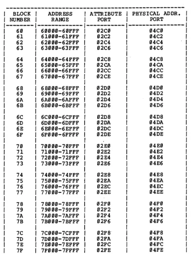
PAGES IN MEMORY
The one million bytes of main memory are managed as 256 pages of 4K (4,~96) bytes each. Each page is assigned a relocation value, and thirteen flag and control bits. This memory relocation and attribute data is stored in a static RAM.
When memory is accessed, the relocation value is used to map the access onto the desired physical memory location. At the same time attribute bits are examined to test the validity of the access.
The violation port is the first of the three error reporting registers supported by the memory manager. This 16- bit register indica tes the type of memory access violation that has occur red. Two other I/O ports are used to report the address at which the violation occurred.
ERASABLE-PROGRAMMABLE-READ-ONLY-MEMORY (EPROM)
The system contains 8-Kbytes of Read Only Memory (ROM) pr i mar ily intended for bootstr apping purpose s. Thi s memory is currently implemented with two 2732 type Erasable Programmable Read Only Memory (EPROM) devices. However the hardware can be strapped to accommodate 27l6-type devices if less EPROM memory is required. This memory overlays the uppermost 8-Kbytes of the 1-Mbyte RAM memory space when 2732-type devices are used.
When 27l6-type devices are used the uppermost 4-Kbytes of RAM are overlayed. This memory can be switched out of memory to permit access to a full Mbyte of RAM. Boot memory contains a unique system serial number that permits software to be "locked" to a specific hardware system. In addition to the serial number, boot memory contains system configuration information.
FLOPPY DISK CONTROLLER
The main board of the ACS 860~ system contains a floppy diskette controller. This controller is implemented with LSI devices and can support up to four 8-inch floppy diskette drives operating in either single-density or double-density recording mode.
PRBLIIIDIARY 8611 OSER IlAlmAL sacrIOR 1. IRT.RODOC~IOR
HARD DISK CONTROLLER
The system provides additional high-speed mass storage through a generalized parallel interface to a family of rigid disk controller boards that mount directly to the CPU board. This interface can support rigid disk controllers with an a-bit data path. This type of rigid disk controller and interface provides a future growth path that permits the support of 5-inch Winchester disks as well as other disk drive technologies.
The initial member of the family of daughter boards provide a controller for the 8-inch Winchester-type hard disks. The controller supports one or two drives, giving mas~ storage capability ranging from lS- to as-Mbytes.
PARALLEL INTERFACE
A 24-bit programmable parallel interface is provided on the main system board. This interface is primarily for driving high-speed line printers but may be reconfigured (by software) to support a wide variety of applications •. It is implemented with an a255 Programmable Peripheral Interface (PPI) device which contains thr ee 8-bi t por ts. Por ts A and B of the a255 ar e buffered with bi-directional buffers that permi~ these ports to be used for either input or output. - Port C is buffered with a unidirectional buffer that provides three bits of input and five bits of output. The buffer ing on Port C supports the handshake and interrupt signals used by port B in mode one.
SERIAL CHANNELS
The system provides a m1n1mum of two, and a maximum of eight serial channels. Two channels are contained on the main CPU board and are primarily intended for standalone operation in manufacturing test. The other eight are contained on an Intelligent Serial Concentrator Board. One channel on the CPU board can be strapped fot either synchronous or asynchronous operation. This multipurpose channels can be strapped to interface to a variety of networks operating at data r~tes up to ass kilobits per second. All serial channels on the CPU board are supported with fully vector ed inter rupts.
(Some system configurations may be offered·which will not include the Intelligent Serial Concentrator Board.)
INTELLIGENT SERIAL CONCENTRATOR
;
The Intelligent Serial Concentrator Board consists of a zas processor with eight serial channels under its control. This board interfaces to the main board through the Multibus interface. The Z8S processor communicates with the aS86 via main memory and a pair of interrupt lines. The aSa6 may interrupt the zas and the zas may interrupt the aSa6. The eight serial channels are capable of operating in asynchronous mode at all
PRBLIIIIlIARY 8688 OSER DIIOAL SBC'rIOR 1. IJrmOOOC'fIOR
standard baud rates between 119 baud and 38.4 kilobaud.
In addition, one channel has provisions for external clocking on both transmit and receive clocks to support bi-synchronous serial devices. Each serial channel has a corresponding programmable timer for baud rate generation to allow for independent baud rates. This board is intended to decrease activity in the host processor so that the majority of character interrupt processing may be handled by the Intelligent I/O. This should allow the host processor to devote more of ita power to higher level tasks and handle users in a more timely fashion.
MAGNETIC TAPE UNIT DRIVE CONTROLLER
A magnetic tape drive controller, capable of controlling up to eight tape transports, can be mounted on the CPU board. This controller controls a DEI Funnel Tape Transport with a the codec' and controller options installed. This combination provides complete archival and backup capability for the rigid disks on the system.
MULTIBUS CARD CAGE
An additional enclosure, containing a standard Multibus card cage, can be connected through rear-panel connections on the primary enclorure. This expansion capability allows system users to add custom interfaces to the system. The interface supports both 8-bit and l6-bit bus masters that use the daisy chain technique ,for resolving the priority of bus requests. Multibus interface design includes socketed termination resistors for all Multibus signals that must be terminated on one of the bus masters. The signals in the int~rface meet the electrical and driver-receiver requirements of the Multibus Specification published by Intel.
CORVBlftIORS
Altos Computer Systems manufactures equipment for both domestic and foreign markets. Domestic equipment operates on lIS-volt AC power; foreign equipment operates on 239-volt AC power. Domestic equipment is identified by an RAR after the model designator on the back panel identfication plate; foreign equipment is identified by an RER. This convention is sometimes reflected in the part numbering scheme, wherein the final three digits "99lR usually designate domestic-use parts and n992 n usually designate foreign-use parts. For brevity, the final three digits of part numbers may be omitted in this manual.
'l'BRIIS AIID ABBRJNIA'l'IORS
For brevity, the following abbreviations are used in this manual:
PRBLlllIllARY 8688
usa
IlUtJAL SBCrIOR 1. rRT.RODOC~IORMTU MTC CPU HDU HDC PCB Kbyte Mbyte
RBLA~BD PUBLlCA'lIORS
Magnetic Tape Unit or Transport Magnetic Tape Controller (board) Central Processing Unit (board) Hard (Rigid) Disk (Drive) Unit Hard Disk Controller (board) Printed Circuit Board
Kilobyte (one thousand bytes) Megabyte (one million bytes)
The following publications are related to or used wih the ACS 8699 Computer System:
(LIST TO COME)
PRBLIIIDIARY 8688 USER IlAllUAL SECTIOR 2. XRSTALLATIOH
SB~IOR 2.
URPACURG ABO SBftIBG UP TIIB COIlPlftER SYSTBII
GBRERAL IHFORIIATIOR
This section explains how to: Select a computer site.
Unpack the shipping container.
store important papers for future reference. Configure the system (if necessary).
Connect maj or system components (computer-,CRT terminal, and pr inter) •
Turn on major components.
SBLBC".rIE A COIIPUTBR. SITE
The ACS 8600 Computer System is rugged and dependable under any reasonable conditions, however, it operates most sa tisfactor ily
when conditions are as close to ideal as possible. Consider the human needs of the operator7 light, comfort, quiet, etc.
Power cords and interconnect cables should be routed to avoid walkways.
Power cor ds should be plugged into a single power str ip of adequate capacity. A dedicated power line is recommended to minimize the liklihood of power surges or overloads.
PRBLIIlIBARY 8611
osa
IWIOAL SBC'lIOB 2. I8S'l'MJ.A~IOBBe sure that the AC input voltage coDforas to that specified on the 8611 co.puter rear-panel Identification !age
Positiion the terminal so that it faces away
in order to reduce screen glare. from, windows Either select an area with minimal static electricity, or use anti-static mats and other anti-static materials as necessary.
Ensure that air flow through the top intake vents and the rear exhaust vent is not obstructed.
Remote multiple-user terminals may be located anywhere that can be reached by a communications cable of up to 58 feet in length.
ONPACKIaG
Remove the computer system from the shipping container as follows:
Turn the shipping container right side up and carefully cut the binding tape and open the container.
~IOB
Ose reasonable care in opeDing the shipping container, sharp or pointed iDstruaents .ay pierce the PEotective cover and scratch the finish of the co.pater housing.
Note the method of packing, and remove the computer components. Store pertinent papers in a safe place for future reference.
Gently tip the container on its side and slide out the computer chassis and the foam packing pieces. Place the chassis on a suitable work surface and replace the molded foam pieces in the container.
store the shipping container and the packing materials in a safe place (in case the computer must be shipped again). The following items are included in the shipping container. Check off each item as it is unpacked.
One Altos ACS 868B Computer
PRBLllllBARY 8611 OSER IIAIIOAL S~IOR 2. IRS~ALLA~IOR
One three pronged power cord
Either one 4-ampere fuse (for 115 vac systems), or one 2-ampere fuse (for 230 vac systems)
One Supplement 3. EXECUTING THE ALTOS DIAGNOSTIC EXECUTIVE (ADX) PROGRAMS and one floppy diskette containing the ADX programs used to test your computer
~rt~ .
One Supplement 4. which provides installation and execution instructions for the operating system to be installed (CP/M- 86, MP /M- 86, OAS 18-16, or XEN IX), and one set of operating system diskettes.
This ACS 8600 Computer System User Manual, accompanied by the following:
One Cover Letter One Checkoff Sheet One Warranty Card
Four Quality Control Reports System Checkoff Sheet System Checkout Sheet Burn-In Summary Sheet
Quality Control Inspection Sheet
ORLOCKna; mB BARD DISK DRIVBS
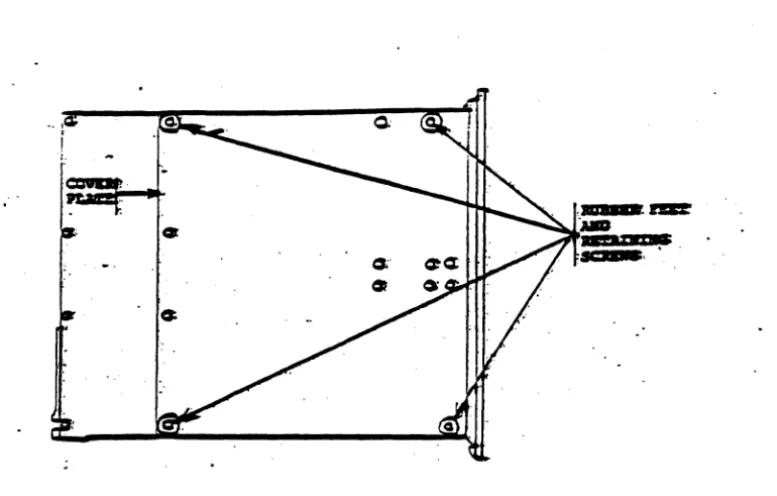
Ra.oving the Botta. COVer Plate
Follow this procedure to remove the bottom cover:
1. Carefully turn the computer enclosure upside down on a non-abrasive work surface.
2. Remove the four retaining screws (Figure 2-1) securing the rubber feet. Save the rubber feet and the four screws.
3. Remove the Bottom Cover Plate (Figure 2-1) and set it aside.
Unlocking the 11-Mbyte Bard Disk Drive
Follow this procedure to unlock the 10-Mbyte Hard Disk Drive:
PRBLIIIIlIARY 8611
osa
IIAIIOAL S~IOR 2. IRS~ALLATIOR1. Remove the screw and locking bracket from tpe hard disk spindle motor (Figure 2-2). store the screw and bracket in a safe place.
CAIJ'lIIOR
fte bracket aDd screw aust be reiDsta1.1ecJ any tiae the coaputer is moved any furtber tbaD it ,is conveDient to band carry it.
2. Replace the bottom cover on the enclosure and secure the four rubber feet previously removed.
3. Carefully return the unit to its upright position and proceed with the installation.
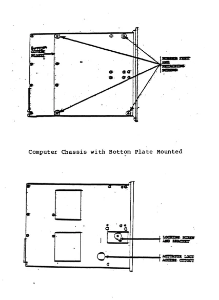
Unlocking the 21-Mbyte or 41-Mbyte Bard Disk Drive
Follow this procedure to unlock either the 29-, or 49-Mbyte Hard Disk Drive:
1. Loosen the drive motor nut (with a hex socket or hex nut driver) from the hard disk spindle motor (Figure
2-3). Rotate the locking cli.p away from the pulley. Do not rotate the pulley. Re-tighten the nut. Do not overtighten.
CAIJ'lIIOR
~be locking clip aust be reinstalled any tiae the co.puter enclosare is moved any fartber tban i t is convenient to band carry it.
2. Locate the Actuator Lock Access cutout (Figure 2-3). USing a straight-bladed screwdriver, rotate the actuator lock counter-clockwise 1/4 turn from the "LOCK" position to the "RUN" position.
3. Replace the Bottom Cover Plate on the computer enclosure and secure the four rubber feet with the four retaining screws previously removed.
4. Carefully return the unit to its upright position and proceed with the installation.
PRELllllRARY 86"" OSER IIAIIOAL S~IOB 2. IRSTALLATIOB
computer Chassis with Bottom Plate Mounted
!It-
=
0
I
I
J
~
-~.
o ·
0-Computer Chassis with Bottom Plate Removed and Locking Devices Exposed Figure 2-1. Unlocking the l~-Mbyte Hard Disk
[image:37.618.127.516.75.323.2]PRBLIIlIlIARY 86 •• USER MAIIOAL SBCl'IOB 2. DlSTALLATIOR
computer Chassis with Bottom Plate Mounted
o
o
Computer Chassis with Bottom Plate Removed and Locking Devices Exposed Figure 2-2. Unlocking the 29-, or 49-Mbyte Hard Disk
[image:38.615.99.527.54.639.2]PRBLIIIIlIARY 8611 OSER IIAIIOAL SEerIOR 2. IBSTALLATION
SYSTEII CONFIGURATION
(Refer to Appendix C. COMMON CRT AND PRINTER INTERFACE CONFIGURATIONS, and Appendix D. INSTRUCTIONS FOR PINNING CIRCUIT BOARDS. )
A complete ACS 86~~ Computer System includes:
An 86~~ computer (complete with power cord, fuse and fuse cap. )
Model ACS 86~~-1~, -l~ MTU, -12, -12 MTU, -14, or -14 MTU.
A user-supplied keyboard CRT terminal.
Serial data transmission rate of 96~~ Baud required. RS-232-C interface.
Optionally, a user-supplied printer (dot matrix or impact quality print).
RS-232-C serial or Centronics parallel interface, one or two (one serial and one parallel interface) can be supported, depending on the operating system used.
User-supplied interface cables for the terminal and printer. To maintain Class A compliance and limit possible radio/TV interference, all interface cables should have a grounded shield and be electrically and mechanically secure to the units to which they are connected.
Altos Diagnostic Executive (ADX) program diskette and operating instructions (contained in Supplement 3).
Provided with the system.
Operating system diskette(s), installation instructions (provided in Supplement 4) and supporting publications.
At least one operating system is required. The diskettes, instructions, required pblications must be purchased separately from the system.
NOTE
All operating syste.s are registered with the licensed seller and distributed under license to the end user to operate only on a single co.puter. CP/II-86, IIP/K-86, OASIS-18, and XERIX must be purchased from Altos Computer Systems and the diskette labe1 should so identify it, with a version number and ser ial number. No other copies of these systems are authorized except by specia1 agree.ent.
PRELIMDlARY 86"" USER IlAllUAL SBCTIOR 2. IRSTALLATIOR
CORRECTDJG PERIPHERAL BQUIPMB!ft'
Install the interface cables and power cords for the terminal(s) and printer (s).
Console Terminal
The console terminal communications cable must be connected from the RS-232-C port from the terminal to serial port 1 of the 86ee computer (reference Figure 2-3). The terminal must be programmed to communicate with serial port 1 of the 86ee computer according to the parameters specified below:
ROTB
Most RS-232-C interface cables can be easily made using .ale shielded RS-232-C 25-pin type connectors and connecting the pins in a one-to-one correspondence. All cables should be fastened with the connector retaining screws to provide a proper shield ground path.
RS-232-C serial communications 96ee Baud
Asynchronous Mode with Data-Terminal-Ready (DTR) handshaking. Request-to-send (RTS) and clear-to-send (CTS) handshaking is disabled
One start-and-stop bit No parity bit
Eight-bit word length
The pinout signals for the console terminal port (port 1) are as follows:
PIN 1 PIN 2 PIN 3 PIN 4 PIN 5 PIN 6 PIN 7 PIN 8 PIN 9
PIN
Ie
PIN 11 PIN 12 PIN 13 PIN 14 PIN 15
Chassis Ground
Transmitted Data (from the terminal) Received Data (to the terminal)
Request-to-Send (optional--requires jumper change) Clear-to-Send
Data set Ready Signal Ground +12 vdc
N/C N/C N/C N/C N/C N/C N/C
PRBLIIIIlIARY 8611 OSER MAIIUAL S~IOR 2. IIISTALLATIOR
PIN 16 PIN 17
PIN 18 PIN 19 PIN 20
N/C N/C N/C N/C
Data-Terminal-Ready (DTR)
CODBCTIE mB POWER SOURCB 1'0 mB COIlPO'lER
To provide power to the computer:
Ver ify that the power specifica tions on the rear panel identification plate match the voltage available for the equipment (see Figure 2-3) •
Domestic equipment uses 115 volts AC and a 2-ampere fuse, and is designated by an nAn after the model number; foreign equipment uses 230 volts AC and a
4-ampere fuse, and is designated by an nE n after the model number;
Insert the fuse and fuse cap (provided wih the system) into the fuse receptacle in the rear panel.
Install the three-pronged power cord in the rear panel AC receptacle and plug it into a power source (wall plug, etc.).
Be certain that the floppy disk transport (or the magnetic tape cartridge transport) is unloaded and the door is open. Turn the terminal on and allow sufficient warmup time so computer messages can be observed when that unit is turned on.
Press the top half of the power switch located at the upper right hand corner of the front panel. The power indicator will light and the following message will appear on the screen.
ALTOS COMPUTER SYSTEMS MONITOR VERSION n.nn
PRESS ANY KEY TI INTERRUPT BOOT
Immediately press any key on the keyboard to interrupt the boot process.
You must interrupt the boot process within two seconds.
If the boot process is not interrupted, the follow ing display appears:
PRBLIIlIBARY 8611 OSER IlIIIUAL SBC'lIOR 2. IlISTALLATIOR
BOOTING FROM HARD DISK
.•
Because the operating system has not yet been installed, the computer will not boot successfully. Press the round RESET button (to the left of the POWER switch on the computer front panel) to restart the boot process, then (within two seconds) press any key.
The system is ready for execution of dignostic programs as described in Section 3.
PRBLIRIlIARY 8611 USER IlAllUAL SBC.rIOR 2. IBS'.fALLA~IO.
Fuse
Hard Disk Expansion Connectors
<t> _ _
.",
PORTSMultibus Expansion Connectors
11111.
PS2.,BT .§.. :=RT II
. iIM" _!!
=_
PORT 6 PORT 4
SERIAL PORTS
Magnetic Tape Unit Drive Connector
o
(6/8/82)
Figure 2-3. ACS Computer System - Rear Panel
Revision B. March 22, 1982 PILE: 2IBSTAL3 3/17/82
(