MINI-TEC«b
DATA-SCREEN~
Terminals
Model 1401
PRODUCT
DESCRIPTION
MANUAL
#3154,·02
960 Character Display, 80 characters/line, 12 lines,
Upper Case Characters
Model 2401
1920 Character Display, 80 characterslline, 24 lines"
Upper Case Characters
Model 2402
1920 Character Display, 80 characters/line, 24
lin~sr
Upper/Lowell' Case Characters
INTERACTIVE
AND BLOCK MODE
OLDEST INDEPENDENT COMMERCIAL CRT TERMINAL MANUFACTURER
December 12, 1978
$5.00
SECTION I
SECTION II
SECTION III
SECTION IV
SECTION V
TABLE OF
CONTENTS
INTRODUCTION System Compatibility Unpacking
Configurations
Power & Signal Wiring Inspection/Power On
OPERATING INSTRUCTIONS Keyboard Familiarization Keyboard Operation
Character Keys Function Keys
Operation of the Interface Description of the Interface Code Charts
SELECTABLE FEATURES
OPTIONAL EQUIPMENT Split Baud Rate Switch Keyboard with 15-key pad Hard Copy Adapter
THEORY OF OPERATION & TROUBLESHOOTING GUIDE Model 1401 Theory of Operation
Timing Generator Memory
Counter Control Serial I/O
Model 2401 Theory of Operation Timing Generator
Memory Counter
Character Generator Troubleshooting Guide
Miratel Monitor Adjustments Specifications
Physical Dimensions Spare Parts Description
WARRANTY
DATA-SCREEN-, MINI-TEC™, ARE PRODUCTS MANUFACTUREO BY TEC,INCORPORATED
All Specification Subject to Change Without Notice
1
1 1
1 2
2 3
4
4
6 8 9 11
15 15
16
20 20 ·21 22
24
26 26 27 27
29
32 33 35 36
37
SECTION I
INTRODUCTION
SYSTEM COMPATIBILITY
A variety of standard interface control features are offered by MINI-TEC Terminals to assure compatibility with most sys-tems and display requirements. These terminals provide a versatile, economical input/output station. MIN 1-TEC OAT A-SCREEN Terminals are readily adaptable to any standard computer system and may be connected directly to the computer or located remotely. These units are compatible with, and may replace Teletype~ Models KSR 33 or KSR 35.
UNPACKING
MINI TEe Tl'lllllll.<ls ."" ("lIdlilly packed to Insure safety during shipment. A sheet was attached to the outside of the cartoll,
''''I
lit'S I ""1 "'Sl'l'CIIOIl of the cilrton for possible freight damage. I f you have not alreadY done so, please inspect it ilt tills pOII". Npl<' ,mv Slnns of damage on the bill of lading prior to unpacking. After the eljulpment is unpacked, inspect fm mlSSII"l 1',,, Is III "\1IlS of d,"nage that may have occurred dUring shipment. If any damage is found, note it on the bill of I"dll"l Ip, ,{()sslllle clillins ilt " later date. Also, any equipment that was roughly handled or dropped should be noted on 1111' bill III 1,,,111"1 Illi posslblt' clalills at il later date. Also, apparent, so that if damage IS discovered later It may be claimed. NOTE: All r.iaims far damage incurred in transit must be filed with the carrier.CONFIGURATIONS
MINI·-TEC Terminals are available in three configurations: DESK MOUNTING - See Figures 1 and 36.
This confi(JlIration includes monitor, logic and power supply mounted in a desk top enclosure, RACK MOUNTING WITH MONITOR- See Figures 2and 36.
In this canfi(juration, monitor, logic and power supply are attached to a 12,." (31.1 cm) high panel (cutout to aceomodate tulle faCt') which mounts in standard RETMA 19·inch (48.3 em) racks. If two or more units are racked on top of one another, at Inast 1" of space should be provided between them to allow for proper cooling.
RACK MOUNT WITHOUT MONITOR
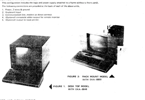
This configuration includes the logic and power supply attached to a frame without a front pami!. The followin,) connections are provided at the back of each of the above units.
1. Pow"r, 2 wires & ground 2. Keyboard input
3 C(lIlllllllllication line, modern or direct connect 4. (Optional) composite video output for remote monitor 5. (OPtional) output to local prillt"'.
~FIGURE
1.POWER AND SiGNAL WIRING
FIGURE 2: RACK MOUNT MODEL . . . WITH EKA-8850
DESK TOP MODE L WI TH E KA-8849
[image:3.614.50.562.353.706.2]INSPECTION/POWER ON
Before connecting power to the terminal, perform the following checks: 1. Examine the unit for external damage.
2. Check for any remaining packing material, masking tape or any other foreign material. No packing material is used inside the desk mount terminal for shipment so it is not necessary to remove the enclosure cover. Should you wish to do so however, remove the back panel (secured with two % turn fasteners, one on each side then pull back the two slide latches at the bottom rear corners, push the shroud forward, and lift straight up to remove. Remove the green ground wire secured with wing nut. [WARNING - This wire must be attached when shroud is replaced.) The rack mount version is of open construction and permits easy inspection before mounting in the rack frame_ NOTE: Power should not be connected to unit until inspection is complete.
3. Visually inspect to assure that the unit is properly grounded via the power connector. A standard three..pin wall socket should be used. Where that is not possible, use a two-pin socket with, proper ground wire attached and con-nected to ground.
4. Check the card rack for loose printed circuit boards.
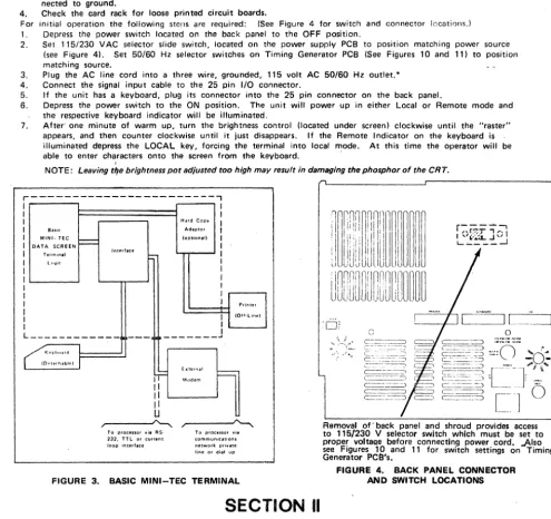
For initial operation the following steps are required: (See Figure 4 for switch and connector locations.) 1. Depress the power switch located on the back panel to the OFF position.
2. Set 115/230 VAC selector slide switch, located on the power supply PCB to position matching power source (see Figure 41. Set SO/50 Hz selector switches on Timing Generator PCB (See Figures 10 and 11) to position matching source.
3. Plug the AC line cord into a three wire, grounded, 115 volt AC 50/60 Hz outlet. *
4. Connect the signal input cable to the 25 pin I/O connector.
5. If the unit has a keyboard, plug its connector into the 25 pin connector on the back panel.
6. Depress the power switch to the ON position. The unit will power up in either Local or Remote mode and the respective keyboard indicator will be illuminated.
7. After' one minute of warm up, turn the brightness control. (located under screen) clockwise until the "raster" appears, and then counter clockwise until it just disappears. If the Remote Indicator on the keyboard is illuminated depress the LOCAL key, forcing the terminal into local mode. At this time the operator will be able to enter characters onto the screen from the keyboard.
,
-NOTE: Leaving tlfe brightness pot adjusted too high may result in damaging the phosphor of the CRT,
r---,
I I
I I
I Hard Copy
I
I BUIC Adlptor I
I MINI-TEe
I
(option. II II DATA SCREEN I
I T.unln.1 Jnlllff.c. l - I
I L '.~i('. I
I I
I I
I I
I I
I I Printer
I
I (Off·line)
I
I I ' - - - - + - '
L._---.JI
[_~:=J
L ____________ I
---
---"'"
o
G
K '" ,,,"'. IOrtllrh.bhdI'F
Exterrlal
==-Modem
II II II U
To procenor yj. RS· To proClssor vie 232. TTL or current communications loop interf.ce network private line or dial up
FIGURE 3. BASIC MINI-TEC TERMINAL
Removal of' back panel and shroud provides access to 115/230 V selector switch which must be set to proper voltaQe before connecting power cord. -Also see Figures 10 and 11 for switch settings on Timing Generator PCS's.
FIGURE 4. BACK PANEL CONNECTOR AND SWITCH LOCATIONS
SECTION II
OPERATING INSTRUCTIONS
KEYBOARD FAMILIARZATION
MINI-TEC DATA-SCREEN Terminals utilize the basic keyboard arrangement of a typewriter to simplify operator transition" To practice typing, turn on power, depress the LOCAL key. then depress the REPEAT key and simultaneously depress any displayable character key. Characters will appear on the screen from left to right. Nea"r the end of a line an audible signal in the keyboard will sound (NOTE: A switch will disable this feature if desired). See Section III, Figure 14 and 15. After the bottom line of the screen is filled, the cursor will return to the top line of the screen and begin writing over data on this line and the previously entered information will be lost unless Automatic Roll-Up is selected (discussed under "Line Feed," page 4).
Depress each of the standard alphanumeric keys and verify that the correct character is displayed on the screen. Depress the shift key and verify that all shiftable characters are displayed properly.
*If 230 volt operation is to be used, replace plug on power cable supplied with a listed plug for that service. Also, replace the 2-amp fuse with a 1 ampere slow-blow type.
[image:4.621.57.553.159.625.2]KEYBOARD OPERATION
Most of the keys on the keyboard generate ASCII codes. These keys are classified as character keys or function keys. In order for the character to be displayed or the function performed, the code must be received by the terminal. This can be done three ways:
1. In LOCAL mode no codes are transmitted to the interface but an internal connection couples the terminal trans-mitter to the terminal receiver.
2. In half-duplex, the codes are sent over the interface and at the same time sent to the terminal receiver.
3 •. In full-duplex, the codes are sent to the interface only. The codes must be echoed back to the terminal by the processor or other davice at the other end of the communication line.
Those keys which do not generate ASCII codes and their purpose are:
SHIFT KEYS - Cause keyboard circuitry to change the polarity of bit 5 of the outgoing data code if, and only if. the key is designated as a shiftable key. Shiftable keys are all keys that have two symbols on the key top. Model 2402 provides lower case alpha characters and upper case in "shift."
CONTROL KEY - Used in conjunction with the keys that normally generate character codes, the control key causes bit 7 to be a logic
0
and therefore the code generated to be changed to those codes shown in columns 0 and 1 of the ASCII code sat. This allows the keyboard to generate many additional codes. Most of the codes generated in this way are not used by the terminal, but may be used in communicating with the processor. The operator must hold down the control key simultaneously with a character key to generate a control code.BREAK KEY - This key causes the communications line to go to the spa~ing level for as long as the key is de· pressed, if the terminal is in REMOTE mode. This key also is used to cause the optional Hard Copy Adapter to stop printing.
REPEAT KEY - When used in conjunction with another character or function key, the ASCII code for that char-acter or function will be repeatedly transmitted (and displayed) at a maximum rate of 15 Hz. At transfer rates below 160 baud, 'the REPEAT function will OCC;Jr as fast as the communication line allows. Data will not be
transmitted when 'the terminal is in LOCAL mode.
LOCAL KEY - Switches the terminal to the LOCAL mode of operation. Allows data to be entered on the screen from the keyboard without being transmitted over the communication line. The transmitter and receiver external connections are disabled. An internal connection to couple terminal transmitter and receiver is enabled.
REMOTE KEY - Switches the terminal to the REMOTE condition. The transmitter and receiver external connections are enebled. If operation is in full-duplex, the internal connection between transmitter and receiver is disabled.
NOTE: All ASCII codes referred to in this manual are in hexadecimal notation. See code charts on page 9 . .. HI FT LOCK - Depression of this key will lock the keyboard into "shift" mode (explained above) to release the
keyboard from "lock" depress the 'shift' key.
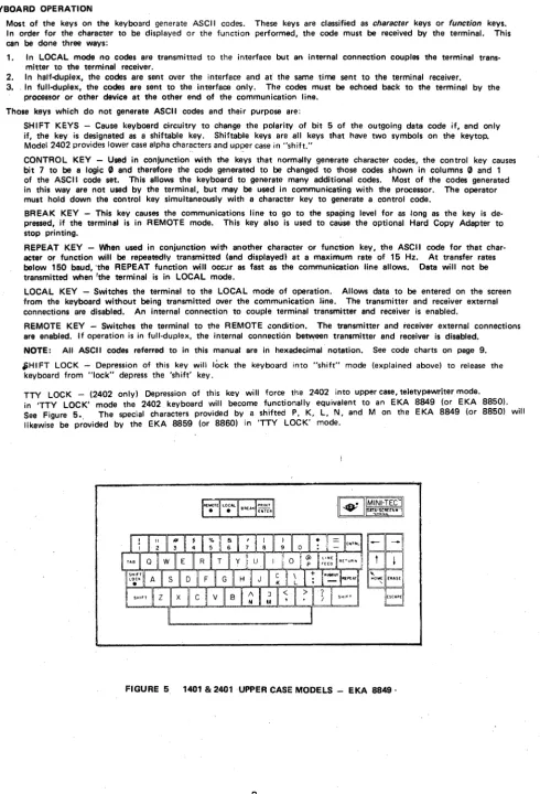
TTY LOCK - (2402 only) Depression of this key will force the 2402 into upper case, teletypewriter mode. in 'TTY LOCK' mode the 2402 keyboard will become functionally equivalent to an EKA 8849 (or EKA 8850).
See Figure 5., The special characters provided by a shifted P, K, L, N. and M on the EKA 8849 (or 8850) will likewise be provided by the EKA 8859 (or 8860) in 'TTY LOCK' mode.
FIGURE 5 1401 & 2401 UPPER CASE MODELS - EKA 8849·
[image:5.614.55.546.57.778.2]FIGURE 6. 2402 UPPER/LOWER CASE MODEL EKA-8859 CHARACTER KEYS
64 alphanumeric characters including punctuation marks and space are provided on the 1401 and 2401. These character codes are those contained in the center four columns of the ASCII code chart. 93 alphanumeric characters are provided on the 2402 and includes the 64 character set of the 1401 and 2401 in addition to the characters listed in the last two columns of the ASCII chart. (NOTE: ASCII codes lC,lE&lFonkeyboardare displayed but not generated.)
FUNCTION KEYS
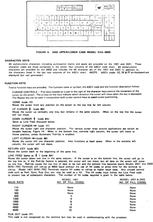
Twelve function keys are provided. The function name or symbol, the ASCII code and the function description follow: CURSOR CONTROLS - Five keys located on a pad to the right of the e!1araeter keys control the' movement of the cursor on the screen. The arrows on the keys indicate which direction the cursor will move when the key is depressed. The Repeat key can be used in conjunction with cursor control keys to speed cursor positioning.
HOME (code 1 EI
Moves the cursor from any position on the screen to the top line far left column. UP CURSOR. (code 0BI
Moves the cursor up vertically one line, but remains in the seme colurtin. When on the top line the cursor will not move.
DOWN CURSOR
t
(code GAl Same as Line Feed discussed below. RIGHT CURSOR'" (code 1 FIMoves the cursor right one character position. For various cursor wrap around applications see switch se-lectable features, Figure 14. When in the bottom line, extreme right column, the cursor will move to Home position, unless Automatic Roll-Up is enabled. .
LEFT CURSOR ~ (code G81
Moves the cursor left one character position. Also functions as beek space. When in the extreme left column, the cursor will not move.
RETURN KEY (code GO)
Moves the cursor back to the beginning of the same line. LINE FEED (same as
t )
(code GA)Moves the cursor down one line in the same column. If the cursor is on the bottom line. the cursor will. go to the top line or. if the Roll-Up feature is selected. the cursor will not move. but all data on the screen will move up one line. Roll-Up causes the top line of data to be lost and the bottom line becomes blank. Models 2401 and 2402
MINI-TEC Terminals will roll-up at 9600 baud without the U8B of fill coc:Ies to allow time for the terminal to roll-up. Model 1401 MINI-TEC Terminals require fill codes to roll-up at higher baud rates. Any unused control code such as Null. Sync. Rub Out, etc. may be used as a fill. The fill codes must follow the Line Feed code to prevent loss of subsequent characters. The number of fill codes required is given in the table below: BAUD RATE
110 150 300
600 1200 1800
2400 4800 9600
RUB OUT (code 7F)
MODEL 1401
NO. OF FI LL CODES None None None
2
4 6
8
16
32
MODEL 2401 & 2402
[image:6.615.66.554.58.767.2]TAB (code 09)
Moves the cursor to the beginning of the next variable (unprotected) field. The cursor will go to the Home posi-tion if no protected field exists. A single protected character position will define a TAB stop.
ERASE (code 0C)
Will cause all unprotected characters to be erased and .replaced with spaces starting at the cursor position and end-ing at the end of the page. The cursor will not move. Blinking format will be reset in the erased area. If LOCK is set, protected characters will also be erased.
CLEAR (code lC)
Moves the cursor to Home and clears all data, both protected and unprotected. This code also resets start protect and start blink. The CLEAR code is the shifted erase code.
ESCAPE (code 1 B)
Depressing this key instructs the terminal to interpret certain alpha codes immediately following the ESCAPE as
functions. Any other code immediately following ESCAPE will be ignored. The function codes which must
fol-Iowan ESCAPE are:
Lock (4C) Release (55) Start Protect (50) End Protect (43)
Start Blin k (42) End Blink (53)
Load Cursor Address (46) Read Cursor Address (52)
The two codes listed after the following functions must be received sequentially to cause that function. Ex-ample: Lock (Escape/Ll is caused by receiving the Escape code followed by the "L" code. These functions
are normally only performed by the computer. However, the operator may generate any of them in LOCAL
mode by depressing Escape and then the proper alpha key. The functions of these codes are:
LOCK (Escape/L) forces the interface into full-duplex. This is to lock the keyboard if the computer does
not echo back to the terminal. Lock also inhibits the format protect, allowing access to the protected fields.
RELEASE (Escape/U) allows half-<!uplex and enables protect.
START PROTECT (Escape/P) defines the beginning of protected data. All displayable characters sent to the
terminal aftet a Start Protect will be protected even though the cursor may be repositioned during the se-quence. Protected data is displayed at reduced intensity. The intensity of the protected data can be ad-justed (see Switch Selectable Features, Section 1111.
NOTE: If the last charecter in a line is protected, then during a block transmit the terminal will not trans-mit a CR at the end of that line. If transmit line is selected, the terminal will not stop at the end of the line. If the last character on the page is protected, the terminal will not transmit ETX.
END PROTECT (Escape/C) terminates loading of protected data.
START BLINK (Escape/B) precedes a group of characters which will blink on the screen. All characters
en-tered after Start Blink and before End Blink will blink even if the cursor is repositioned.
END BLINK (Escape/S) terminates the loading of blinking characters.
NOTE: Start Blink, End Blink, Start Protect, and End Protect do not occupy space in memory.
LOAD CURSOR ADDRESS (Escape/F) causes the next two codes received to be interpreted as the one's com-plement of the horizontal and vertical cursor address.
READ CURSOR ADDRESS (Escape/R) will cause the terminal to transmit two characters which are the one's complement of the horizontal, then the vertical cursor address.
NOTE: In Model 1401, RCA will not work in systems with either hardware or software echo-back. If you
are operating in half-<!uplex the CPU should lock the keyboard (Escape/L), Read the address (Escape/R), then release the keyboard (Escape/UI.
ENTER (coda (2)
The ENTER key generates and transmits on the communication line the code 02 (ASCII STX) for use in control
of the Block Transmit function. Block transmission is initiated when the terminal receives an STX (02) or an
EOT (041. One of these two codes must be used as determined by a selector switch on the Control PCB (see
Section III).
When the block transmission mode is initiated, the first character sent is the character at the cursor location. The cursor then moves to the next location and that character is sent. If two successive space codes (20) are transmitted and the Space Code Delete function is selected (by a switch located on the Serial I/O PCB see Section III) the following successive spaces on that line .are skipped over and not sent, except that the last character on each lina is transmitted. If the Space Code Delete function is not selected, all codes are transmitted.
Protected areas on the screen are skipped over and not transmitted unless the LOCK is set. A CARRIAGE
RETURN code (00) is automatically inserted after the last character in a line and if the Transmit-to-End-of-Line function is selected transmission ends with the cursor located under the first character in the next line.
NOTE: If Transmit CR code at end of line is disabled Line Transmit Mode is also disabled and the terminal
will be automaticallv forced into page or block mode. (See Figures 17 and 18). If the Transmit-to-End-of-Page function is selected, an ETX code (Q'l3) is inserted) after the last character on the last line and transmission ends with the cursor returned to Home.
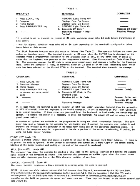
Normal operation for the block transmission mode follows (See Table 1): The operator places the terminal
in the local mode using the LOCAL key on the keyboard. The cursor is positioned to the desired be-ginning point of the message using the cursor controls. The message is typed and corrected until the oper-ator is satisfied. The Transmit-to·End·of-Line. Transmit·to·End·of·Page switch located inside the terminal on the Motherboard PCB is set to the desired function (at the factory), and the Cursor IS repositioned to the beginning
of the message (usu<llly HOME l. . NOTE: Switch function may be changed on the location bv removal of the back panel and shroud. When red toggle toward fan· Transmit·to·End·of.page, when red toggle away from fan-Tra~$mit-to-End-of-Line. The operator Initiates transmission of data by depressing the PRINT/ENTER key.
OPERATOR 1. Press LOCAL key
2. Compose 3. Home Cursor
4. Press PRINT/ENTER key 5.
.,.' "
TABLE 1. TERMINAL
REMOTE Light Turns Off Displays Data On Screen Displays Data 0" Screen a. REMOTE Light Turns On b. Transmits 132
Code-Transmits Message- - (Half Duplex)
COMPUTER
-Receives 02 Code-Receives Message
·If terminal is set to transmit on receipt of 04 code, computer must echo 04 code before transmission of data occurs .
• ·For full duplex, computer must echo 02 or 04 code depending on the terminal's configuration before transmission of data occurs.
The Block Transmit function may also occur as follows (See Table 21: The operator follows the same pro-cedure as described above. The terminal transmits an 02 code when the ENTER key is depressed or the operator types a programmed instruction to the processor such as ESC, or any other code or group of codes that the keyboard can generate at the programmer's option. (See Communications Code Chart Page
9). The computer receives the 02 code or other prearranged query and reserves a buffer for the incoming data. When the computer is ready, it transmits either an 02 code or an (J4 code (depending upon which code has been selected on the Control PCB) to the terminal. The terminal then transmits the message.
OPERATOFJ
1. Press LOCAL key 2. Compose Message. 3. Home Cursor
4. Press PRINT/ENTER key or remote and prearranged code
5. 6.
TABLE 2. TERMINAL
REMOTE Light Turns Off Displays Data On Screen Displays Data On· Screen a. REMOTE Light Turns On b. Transmits 02 Code or
Pra-arranged Code
Receives 02 or 04 Code Transmits Message
COMPUTER
Receives Code(s) Reserves Buffer and Transmits (12 or 04. Receives Message If, in local mode, the terminal is set to transmit on STX (see switch selectable features) then the generation of STX (Control/B) from the keyboard is an invalid operation. If set to transmit an EDT, then Control/D is an invalid operation. If these codes are generated from tha keyboard, in local mode, the cursor may dis-appear. To restore the cursor it is necessary to cycle the terminll's AC power off and on using the back panel power switch.
A number of options are available to the programmer in using the block transmission function. The com· puter may send a message to the operator for verification and, if needed, the operator may update it and transmit the message to the computer in its latest form using one of the sequences described above. In addition, the computer may be programmed to handle a portion of the cursor repositioning, if desired, by using the Load Cursor function.
PRINT KEY (code 12)
Generates a shifted ENTER code and causes a signal to be sent to the optional Hard Copy Adapter. If there is no printer the code is ignored. If the printer is connected and turned on, a Hard Copy of the screen display (starting at the cursor location and ending at the end of the screen) is produced.
BELL [Control/G] (coc,ie (17)
The computer may signal the operator by sending a BEL code to ·the terminal interface and causing the audible signal located in the keyboard to sound. The terminal also generates an audible signal when the cursor moves from the 68th character position to the 69th character position of any line.
CANCEL [Control/X) (code 18)
The cancel function terminates a block transmit in progress when the code is received.
NOTE: If lower case alpha codes in columns 6 & 7 of the code chart (Figure g) are received by the 1401 and 2401, th"y will be stored as the corresponding uppercase code in columns 4 & 5. The one exception is Rub Out (7F) which will be ignored. On the 2402 alpha codes in columns 6 & 7are displayed as lowercase. Three additional keys are
provided on the 2402 to generate the upper and lower case set. These keys are located in the cursor control pad (see Figure 6).
OPERATION OF THE INTERFACE
[image:8.611.60.536.43.677.2]FULL OR HALF·DUPLEX
Operation mode may be switch·selected by the operator to either fUIl-duplex or half-duplex. In full-duplex the key-board and serial transmitter serve as an independent unit driving the "transmit" side of the communications line. The serial receiver and the basic display are driven by the "receive" side of the communications line. In order to record keyboard data on the screen in full-duplex mode, the processor at the other end of the communications line must "echo" the character back via the "receive" line.
In half-duplex operation, an internal connection is made to receive directly any character transmitted as \111811 as receive any character arriving via the communication line. Thus, any character typed will apoear on the screen without "echo-ingl/ the character externally. However, if a character is generated internally at or near the same time as one is re-ceived via the communications line, the result will be garbled with the bits of both characters OR'ed together. LOCAL-REMOTE
The operator may keyboard-select remote or local operation. In remote operation the interface operates as described previously. When the terminal is set in the 10cClI mode, all three transmitting interfaces are forced to the "Marking" condition, the external receiver line is disabled and the unit is forced into half-duplex regardless of the position of tha communications-mode SWitch. The local condition is used primarily for checkout of the display, for operator training and for generating messages for block transmit operation.
OUTGOING SIGNAL
The interface will accept keyboard codes, serialize them, add the proper control and parity and place them on the out-going signal lines. See the Keyboard Data Code Chart for the codes that can be generated by the keyboard and trans-mitted by the SERIAL I/O PCB.
The "break" key on the keyboard does not generate a code, but causes the outgoing signal to go to the "Spacing" level for as long as the key is depressed. (RS-232: +8V; TTL: +5V; Current Loop: open circuit!.
BAUD RATE SWITCH FEATURE
,
A baud rate switch is provided which allows rapid sE!lection of one of nine prE!-5E!t baud rates bet\lll8en 110 and 9600 baud. The switch is located on the back panel of desk mount and rack mount MINI-TEC DATA-SCREEN Terminal displays. Sea Figure 4. For adjustment procedure, see page 24.
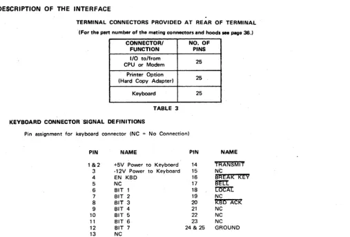
DESCRIPTION OF THE INTERFACE
TERMINAL CONNECTORS PROVIDED AT REAR OF TERMINAL . (For the part number of the mating connectors and hoods saa page 36.1
CONNECTOR/ NO. OF
FUNCTION PINS
I/O to/from
25 CPU or Modem
Printer Option
25 (Hard Copy Adapted
KE!yboard 25
TABLE 3 KEYBOARD CONNECTOR SIGNAL DEFINITIONS
Pin assignment for keyboard connector INC = No Connection)
PIN NAME PIN NAME
1&2 +5V Power to Keyboard 14 TRANSMIT 3 -12V Power to Keyboard 15 Nt:
4 EN KBD 16
BREAk kEY
5 NC 17 ~
6 BIT 1 18 ~
7 BIT 2 19 NC
8 BIT 3 20
KBD
ACK9 BIT 4 21 NC
10 BIT 5 22 NC
11 BIT 6 23 NC
12 BIT 7 24 & 25 GROUND
13 NC
[image:9.623.47.555.356.700.2]INTERFACE DATA TRANSFER BIT SEQUENCE
The following bit sequence is used for the transmitted and received data on all interfaces. Each character is composed of a 10 or "-bit word as shown.
I:
11 91U'I=l
The bit sequence on the communications line is left to right in the diagram shown at left. The stop bit may have a min·10 Bit. imum length of "onti" or "two" bit times and the parity bit
1
5. ' "
I
I I
I
I I I I
S •• pmay be "even," "odd," or "mark" Ibit time is dependent on)
1 2 l
•
5 6 7 P data transfer rate)...
NOTE: Stop bits and parity are pre·set to customer specification, but may be field changed by moving a switch can· nection. See Figures 17 and 18.
Unless otherwise specified, 110 Baud units will be set -for 11 bit word·length, and all other speeds will be set for 10 bit word-length at time of manufacture and final inspection.
INTERFACE CONNECTOR SIGNAL NAME AND FUNCTIONS
Pin Assignment for I/O Communications Connector INC No Connection)
PIN NAME PIN ~
~
1 Frame Ground 14 N C
2 RS·232 Transmit Data lElA) 15 N C
3 RS·232 Receive Data (EIA) 16 N C
4 Request to Send lElA) 17 N C
-5 Clear to Send lElA) 18 Terminal busy IFor use with HCA)
6 N C 19 N C
7 Signal Ground 20 Data Terminal Ready lElA)
8 Carrier Detect lElA) 21 N C
9 TTL Transmit Data 22 N C
10 TTL Receive Data 23 NC
11 +20 mA Ifor use with current loop interface) 24 Current loop Transmit Data 1-)
12 Current loop Transmit Data (+1 25 Current loop Receive Data (-) 13 Current loop Receive Data (+1
MINI·TlC
,..lII",NAL
MINI·TIC TI"Y,,,.L
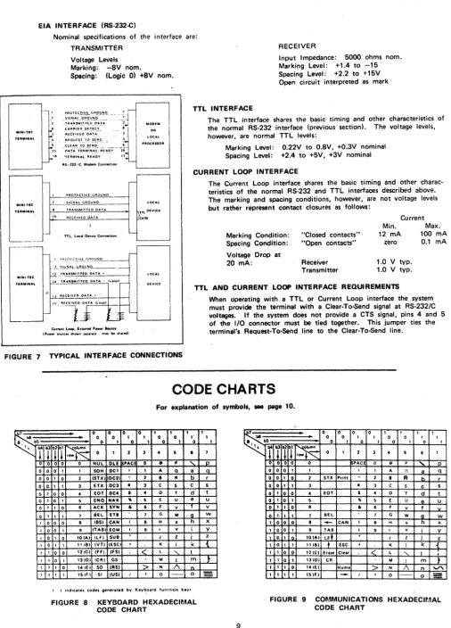
EIA INTERFACE (RS·232-C)
Nominal specifications of the interface are: TRANSMITTER
Voltage Levels Marking: -8V nom.
Spacing: (Logic 0) +8V nom.
,
,
,
fo:
1";.
~; "PROTEC~I.Y.L GA.9Y!!.Q.. ___ -. ___ ~
_I
S'G"!~LCl.t;'.~I!!!Q. __ " . _ ~ TAA,!'IS~.!!T.~D._~:'.!.~ ~..l C~~A~fn_ .!?E_!.~C-'_ •
AfC~IVE':' DA!~ • . . .
PROTECTIVE GROUND
2.. _ _ SIGNAL GROUND , TRANSMITTED OATA
,.
R[CEIVED QATAf- nL. loc .. Dnlce ConMCdon
MODEM
OR
LOCAL
'ROCIlIOR
TTL INTERFACE
RECEIVER
Input Impedance: 5000 ohms nom. Marking Level: +1.4 to -15 Spacing Level: +2.2 to +15V Open circuit interpreted as mark
The TTL interface shares the basic timing and other characteristics of the normal RS·232 interface (previous section), The voltage levels, however, are normal TTL levels:
Marking Level: Spacing Level:
0.22V to O.BV, +0.3V nominal +2.4 to +5V, +3V nominal CURRENT LOOP INTERFACE
The Current Loop interface shares the basic timing and other charac· teristics of the normal R5-232 and TTL interfaces described above. The marking arid spacing conditions, however, are not voltage levels but rather represent contact closures as follows:
Marking Condition:
Current Min. 12 mA
- - - - ' Spacing Condition:
"Closed contacts"
"Open contacts" zero
Max. 100 mA
0.1 mA
.J. __ !llli.~.L.li.!,OIlNO _ _ _ _ 11 __ T!'~~lTnD 0."' . . "'.'-'.'--_ _ _ -1
Voltage Drop at
20 mA: Receiver
Trar:'smitter
1.0 V typo 1.0 V typo
MU,,·lIC
'UMINAL tL TlUNIMITHO DATA· lI .. oapl
TTL AND CURRENT LOOP INTERFACE REQUIREMENTS
Curtent LOCIP, blerMl 'DWtIf Saure. t'nMI' lOUR:n snown leP".'. m.y M ,It.,edl
FIGURE 7 TYPICAL INTERFACE CONNECTIONS
When operating with a TTL or Current Loop interface the system must provide the terminal with a Claar·To-5and signal at RS·232/C voltages. If the system does not provide a CTS signal, pins 4 and 5 of the I/O connector must be tied together. This jumper ties the terminal's Request·To"Send line to the Claar·To-5end line.
CODE CHARTS
For explanation of symbols, _ page 10.
•
a a a a I I I..
.
a a I I a a! a I•
a I a I I a~
.
.~'I,
rrn~
a I 2 3•
I•
o 0 o 0 0 NUL OLE PAC a
..
,
"-a 0 0 0 0 0 0 1 1 1 1 1 1 1
,
o 0 I I SOH OCI 1 I A Q a
0 1 0 2 ISTX) IOC2)
..
2 a"
b0 I I 3 nx OC3
•
3 C S C I 0 0•
EDT DC.•
•
0 T d 1 0 1 $ END NAK"
I E U e1 1 0 6 ACK SVN
•
6 F V 1 1 1 7 BEL ETa 7 G W go 0 0 8 IBSI CAN I 8 H X h
o 0 1 9 ITABI EOM I 9 1 Y i 0 1 0 lOlA) ILF) SUB
,
J Z j 0 1 1 "IB) IVTl IESC)·
K I k 1 0 0 121C) IFFI IFSI<
l "- I 1 0 1 13101 ICAI GS M I m 1 1 0 "lEI SO IRS I>
N 1\"
1 1 1 151F I SI IUSI I
,
0 - - 0 I ) ,"dlut., cod,i gen,r"ed by Keyb.o.rd fun,.tion key.FIGURE 8 KEYBOARD HEXADECIMAL CODE CHAAl;
I I I 1 0 r S t U V W x V .Z 0{
}-=
9~
..
.
.
0 0 0 0 I I 1 10 0 I 1 0 0 1 1
• bI 0 I a I 0 1 0 I
".
rTi7~
a I 2 3•
5 6 7a 0 a a PAC 0
..
p'"
pa a a I I I 1 A Cl a q
a a I a 2 STX Print
..
2 B A b ra o I I 3
•
3 C S C sa I a a
•
EDT $•
D T d tQ I 0 I 5
"
5 E U A U0
•
I a•
•
6 F V f10 I I I 1 Bel 7 G W g W
I a 0 a 8
-
CAN I B H X h xI a a 1 9 TAB I 9 I Y i V
• 0 I IOIAI IF. J Z j Z
I a I I 111BI
+
ESC·
K I k { I I a Oi 12ICI Er ... CI."<
L "- I•
I I a I '3101 CA M I m }I 1 I a 14 lEI Home "> N /\ n
"'"
I I I I 15 IF,
-
I,
0 0=
[image:11.615.45.551.54.758.2]SYMBOL
STX EDT BEL
as (
or ~I TABLF ( or
t
VT ( or
t
FFCR DC2
CAN ESC
FS
RS or \ 1 US or~ 1
ALPHA NUMERIC CHARACTERS RUB OUT
EXPLANATION OF SYMBOLS
Used on Keyboard and Communications Code Charts, Page 9
EXPLANATION
Start of Text. Sent by terminal when Print/Enter key is depressed. Starts Block Mode transmission when received if terminal is so configured (See EDT).
End of Transmission. Starts Block Mode transmission when received if terminal is so configured.
Bell Code. Sounds audible signal in keyboard when received.
Back Space. Moves the cursor left one character position. When in the ex-treme left column the cursor will not move when the BS Code is recaived. Field Tab Code. Moves the cursor to the beginning of the next variable (un-protected) field. The cursor will go to the Home position if no protected field exists. A single protected character position will define a Tab stop.
. Line Feed Code. Moves the cursor down vertically one line, but remains in the same column.' ,When on the bottom line, the cursor will move to the top line, same column or ca'Ise roll-up (See Roll-Up option description on page 4). Reverse line Feed Code. Moves the cursor up vertically one line, but remains in the same column. When on the top line, the cursor will not move when this code is received ..
Erase Code. Will cause all unprotected characters to be erased and replaced with spaces starting at the cursor position and ending at the end of the page. The cursor will not move. Blinking format will be reset in the erased area. If lock is set, protected characters will also be erased.
Carriage Return Code. Moves the cursor to the left column on the same line.
Print Code. Causes a signal to be sent to the optional printer interface. If there is no printer the code is ignored. If a printer is connected and turned on, a hard copy of the screen is produced.
Cancel Code. Will terminate a block transmit when the code is received.
Escape Code. Conditions the terminal to interpret certain alpha codes immediately following the Escape as functions. Any other code immediately following Escape will be ignored.
Clear Code. Will erase the entire screen and the cursor will go to Home. Protect-ed format will also be erasProtect-ed.
Home Code. Moves the cursor to the first position of the top row.
Forward Space Code. Moves the cursor right one character position. When in the right column the cursor will move to the extreme left column of the line below. When in the bottom line extreme right column, the cursor will move to Home position.
Displayable symbols in columns 2 thru 7 of the ASCII standard code chart. (Codes in columns 6 and 7, except RUBOUT, will be recognized as the correspond· ing upper case codes in columns 4 and 5 by the 1401 and 2401.1
SECTION III
SELECTABLE FEATURES
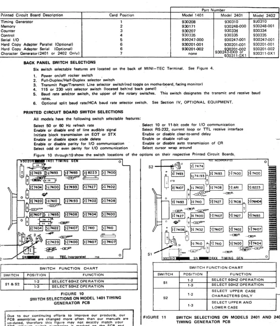
Model 1401 MINI-TEC Terminals have, five standard printed circuit cards; Models 2401 and 2402 terminals have six standard printed circuit cards. The table below lists the PCB's for each model, their description. and the card position.
Part Number
Printed Circuit Board Description Card Position Model 1401 Model 2401 Mode.' 2402
Timing Generetor 1 930208 930310 9J0310
Memory - 2 930171 930248·000 ,930248·001
Counter 3 930207 930~34 930334
Control 4 930335 930335 930335
Serial 1/0 5 930247·000 930247·001 930247"()01 Hard Copy Adapter Parallel (Optional) 6 930201"()01 930201"()01 930201·001 Hard Copy Adaptar Serial (Optional) 6 930201-002
9302~~~~61,92
930201-002 Character Generator(2401 or 2402 Only) 7 none930311·0X 1 930311·0X 1 BACK PANEL SWITCH SELECTIONS
Six switch seiectable features are located on the back of MINI-TEC Terminal. See Figure 4.
;2
r"
•
1. Power onloff rocker switch .
2. Full.Duplex/Half.Duplex selector switch
3. Transmit Page/Transmit Line selector switch(red toggle on motherboard, facing monitor) 4. 115 or 230 volt selector switch (located beh:nd back panel) .
5. Baud rate seleCtor sWitch, the upper of the rotary switches. This switch designates the transmit and receive baud rates.
6. Optional split baud rate/HCA baud rate selector switch. See Section IV, OPTIONAL EQUIPMENT. PRINTED CIRCUIT BOARD SWITCH SELECTIONS
All models have the following switch selectable features: Select 50 or 60 Hz refresh rate
Enable or disable end of line audible signal Initiate block transmission on EOT or STX Enable or disable space code delete
Enable or disable parity for I/O communication Select odd or evan parity for I/O communication
Select 10 or 11·bit code for I/O communication Select RS·232, current loop or TTL receive interface Enable or disable clear·to·send delay
Enable or disable roll·up
Enable or disable auto transmission of CR Select cursor wrap around
Figure 10 through'19 show the switch locations of the options on their respective Printed Circuit Boards.
~"
~F4201 p~740ol
~~ -or::Jll"
~
p:741071 PF41071
rated 758
SWITCH FUNCTION CHART
o
o
51SWITCH FUNCTION CHART
L
SWITCH POSITION FUNCTION SWITCH POSITION FUNCTIONI
S1 & S21·2 SELECT 60HZ OPERATION '·3 SELECT 50HZ OPERATION
FIGURE 10
SWITCH S!:LECTIONS ON MODEL 1401 TIMING GENERATOR PCB
Due to our continuing efforts to improve our products, our PCB assemblies are changed more often than our manuals are , up·datod, therefore this figure may not exactly match your
PCB although switchnlJmbering is marked on the PCB and the .electable features ara the sama.
S1
S2
FIGURE 11
1-2 1-3
1-2
1-3
SELECT 60HZ OPERATION SELECT 50HZ OPERATION
SELECT UPPER CASE CHARACTERS ONLY
SELECT UPPER AND LOWER CASE
[image:13.614.14.568.126.769.2]S3
S1
S2
SWITCH
S1
S2
S3
930171 _ _ MINI-TEe MEMORY BO SN ~ 0
~530067-001 D~ 7450
I D
~ 7450I
P,34091~:7450Ia:74501
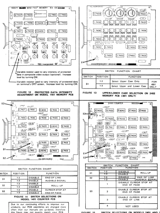
Variable resistor used to vary intensity of protected 118t8 in composite video output (optional), Increase level by turning CW_
I
Variable resistor used to vary intensity of protected data on terminal's CRT screen. Increase level by turning CWo
FIGURE 12 PROTECTED DATA INTENSITY ADJUSTMENT ON MODEL 1401 MEMORY PCB
o
oO.!~z,--_...:°J
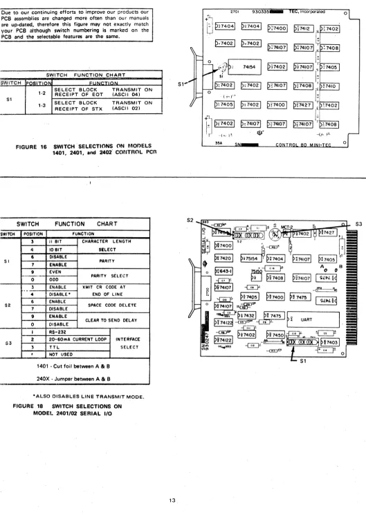
SWITCH FUNCTION CHART
\
POSITION FUNCTION
1-2 DISABLE END OF LINE 1-3 ENABLE AUDIBLE SIGNAL 1-2 ENA'BLE
1-3 DISABLE ROLL-UP
1-2 ENABLE CURSOR STOP AT 1-3 DISABLE END OF PAGE
FIGURE 14 SWITCH SELECTIONS ON MODEL 1401 COUNTER PCB
Due to our continuing efforts to improve our products, our PCB assemblies are changed more often than our manuals are up-dated. therefore this figure may not exactly match your PCB although switch numbering is marked on the PCB "nd the selectable features are the same.
.":
S
2400MEMORY 930248
SWITCH
S1
FIGURE 13
SWITCH
S1
S2
S3
FIGURE 15
SWITCH FUNCTION CHART
POSITION FUNCTION
1-2 Select Upper Case Only
1-3 Select Upper and Lower' Case
FOR
-001'
ONLY
UPPER/LOWER CASE SELECTION ON 2402 MEMORY PCB ,·001 ONL YI
PH420 1
0.
P;74193I
P.74193I
p~
74041.~.~O •
--c!!:J!-~ ...
p~ 7412
I
rp~'-7-4-19-3"'1 p~ B2421 p~ 74193I
~PF
SWITCH FUNCTION CHART
POSITION FUN N
1-2 DISABLE
ROLL-UP ENABLE
1-2 DISABLE END OF LINE
1-3 ENABLE AUDIBLE SIGNAL
DISABLE CURSOR STOP AT END OF PAGE
ENABLE CU RSOR STOP AT
2 END OF PAGE
ENABLE CURSOR STOP AT
3 END OF LINE
4 NOT USED
[image:14.611.41.571.44.751.2]Due to our continuing efforts to improve our products our PCB a$sembiies are changed more often than our manuals are up-dated, therefore this figure may not exactly match your PCB although switch numbering is marked on the PCB and the selectable features are the same.
SWITCH FUNCTION CHART SWITCH IpOgiTION FUI
51
SWITCH
SI
52
53
1·2 SELECT BLOCK RECEIPT OF EaT TRANSMIT ON (ASCII 04) SELECT BLOCK TRANSMIT
1·3 ON
RECEIPT OF STX (ASCII 02)
FIGURE 16 SWITCH" SELECTIONS ON MOr>ELS 1401, 2401, and 2402" CONTROL PCR
" I
SWITCH FUNCTION CHART
POSITION FUNCTION
3 " 81T CHARACTER LENGTH
4 10BIT SILECT
6 OISABLE
PARITY 7 ENABLE
9 EVEN
PARITY SELECT 0 ODD
3 ENABLE lCMIT CR CODE AT
.
-4 DISABLE" END OF LINE
S ENA8LE
SPACE CODE OELETE 7 DISABLE
9 ENABLE
CLEAR TO SEND DELAY 0 DISABLE
I RS-232
2 20-S0mA CURRENT LOOP INTERFACE
3 TTL SELECT
•
NOT USED,.
1401 • Cut foil between A 81 B 240X . Jumper between A 81 B '"
·ALSO DISABLES LINE TRANSMIT MODE.
FIGURE 18 SWITCH SELECTIONS ON MODEL 2401/02 SERIAL I/O
2701 930335 0
+~
U
PH4041 PH4041 P~74001P'"''
I~'
"0'
i
P·"74021 p .. 74021
I~
"
P;741071 P.741071
1
:f
740810
~~t},P~
74154 p~74021p~741071 ~ r~74051
51
"
f~
51" D~74021 p~74021 P?741071
e,,,o'l
~,,,,o
I
0
.-{ ~\.t-'.'"
p~ 74051 p~ 74021 p n400 1
e"427
I
r'
O' :f:J
pn4021 p~741071 PF4I071lu
p~741071 1:7408 'r "-1"' )"' ~. --LA,
tJ!-35A
,--_---, -Ej~~' =='\~I
~~740ol
P9
7475~
- ~
[image:15.611.13.542.42.787.2]SWITCH
S1,2
.
FIGURE 19
S 1,
0
p; 74081
~74021
p; 749
61 p: 74001
,
~2p~
7
4081
~
p~74041 t..---,
::;MKIOO7:
..---~
P:741071 p:MKlOOti
resistor used to vary Intensity of protected data in composite video output (optional) lever by turning CWo
Variable resistor used to vary intensity of rorotected data In composite video output on CRT screen. I ncrease by turning CWo
SWITCH FUNCTION CHART
POSITION FUNCTION
1-2 Select Upper and Lower Case FOR -OXI 1-3 Select Upper Case Only
ONLY
PROTECTED DATA INTENSITY ADJUSTMENT ON MODELS 2401 AND 2402 CHARACTER GENERATOR PCB
[image:16.614.51.566.12.781.2]SPLIT BAUD RATE SWITCH
SECTION IV
OPTIONAL EQUIPMENT
The split baud rate switch is an option which may be added at any time to any MINI-TEC Terminal. Card cages provided with MINI-TEC Terminals are pre·drilled and. pre·punched for the split baud-rate switch, and the back plane mother·board has proviSion for the cable. The back panel is also pre-drilled for the "Receive" rate switch. Retrofit may be done at the fac-tory for an additional charge. If you desire both the split baud rate and Serial Hard Copy Adapter Options please contact TEC Sales Department.
The spll~ baud rate switch assembly (TEC part no; 980077) is used with the standard baud rate switch to allow the terminal to transmit over the communication line at one baud rate and to receive from the communication line at a different baud rata. The use of the split baud rate option requires the terminal to operate in the full-duplex mode. The switch located bp.IQw the duplel( switch is lIs~d for the transmission rate, and thl' othl'r switcll, for the receive rate.
The optional split baud rate switch allows rapid selection of one of nine preset baud rates between 110 and 9600 for the re-ceive baud rate. The standard baud rate switch allows rapid selection of one of nine pre-set baud rates between 110 and 9600 for the transmit baud rate. The split baud rate switch option includes: printed circuit board; switch; oscillator circuits; mount-ing hardware and cable to connect the assembly to the terminal's mother board wirmount-ing.
NOTE: When instill/ing optionslsplit baud rate assembly. the jumper between "A" & "8" on the standard baud rate assembly must be removed.
The following speads are standard:
POSITION BAUD RATE POSITiON BAUD RATE
ccw 1. 110
!
6. 18001
2. 150 7. 2400
3. 300 8. 4800
4. 600 cw 9. 9600
5. 1200
The baud rate oscillator circuits are discussed under Theory of Operation, page 24.
OPTIONS
KEVBOARDS WITH 15 KEV PAD (EKA-8850 AND EKA-8860)
An expanded version of the standard keyboard containing a 15-key pad (10 numeric keys, four symbol keys and 0'19
function key) is available ~s an option on MINI-TEC DATA-SCREEN Terminals.
The 15·key pad is arranged much like a 10·key adding machine to allow'quiCk and simple entry of numerical data by the operator.
FIGUnE 20 EKA 8850 - (liPPER CASE' VERSION
FOR MODELS 1401 AND 2401.)
FIGUnE 21
OPTIONS
COMPOSITE VIDEO OUTPUT
EKA 8860 - (UPPER AND LOWER CASE VERSION FOR MODEL 2402.)
· ~.: [MINI-TEe]
~ .1°ltl,!cRHNtt I
't ... ,~ ••
A second video circuit is available to drive a remote mon itor. This driver combines the serial video data with cursor video, the protect memory bit (for reduced intensity,) and with vertical and horizontal syncs to produce NTSC composite video and sync for a remote monitor. The composite video is pr9vided at a BNC c()nnector on the rear panel.
If th,· composite video output feature is not specified when the unit is ordered, a kit, part number 980079 for tho 1401 and number 980073 for the 2401 and 2402, IS available to ado this feature later.
OPTIONS
HARD COPY ADAPTER INTERFACE DESCRIPTION
There are two Hard Copy Adapter (HCA) options available for the MINI-TEC Terminal; A parallel HCA (Assemply No. 980074) which is compatible with most printers using a "Ready/Strobe" type interface; and a Serial HCA (As. sembly No. 980075) used with RS-232C, current loop, or TTL interfacing.
The Serial HCA uses an additional outboard 06cillator assembly which allows the printer baud rate to be readily
aq-justable from the back panel of the terminal. The split baud rate option and the serial hard copy adaptor cannot be specified together without deviating from standard mechanical design. If both Serial HCA and Spilt Baud Rate options are required, contact TEC's Sales Department.
The HCA initiates printing upon receipt of the print command (ASCII 12) from the keyboard or from the communi-cations line and halts when the CRT screen has been outputed or when the BREAK key is depressed.
On receipt of the print code the HCA sends signals to other areas in the terminal, disabling the keyboard and com-munications line inputs, and also disabling protect which allows all data appearing on the screen (protected qr unpro-tected) to be printed.
The HCA also provides an RS-232C signal called Terminal Ready to the communications connector pin 18. Thi~
signal goes to a positive level when the HCA is outputting to the printer.
The following paragraphs on Parallel & Serial operation assume that all inputs and outputs to and from the printer and the HCA are "true high." However, most of the inputs and outputs to and from the HCA are polarity selec-table by switch.
[image:18.614.68.530.71.612.2]DATA BITS
1-·7
PARALLEL OPERATION
If the Parallel/Serial selector switch is in the Parallel position and ACK and PRINTER READY are "true," and if printer BUSY and the optional print inhibit line are false, the strobe line will be pulsed presenting the first character to the printer, upon receipt of the Print Command. The first character outputed will be an ASCII carriage return
followed immediately by an ASCII line feed followed by the characte~ appearing in the present cursor location. The
cursor will then advance through the data on the CRT screen at a rate determined by the data ACK line. A carriage
return code lind a line feed code will be sent at the and of each line of data. After the whole page has baen trans· mitted to the printer the cursor will return to the Home position, and the keyboard and communication line and pro· tected data will be enabled.
The strobe generated by the HCA can be self·terminating or interactive, see Figure 22 and 23 below. The self ter· terminating or interactive strobe are offered as switch options.
SERIAL OPERATION
If the Parallel/Serial selector switch is in the serial position; "Printer Ready" is true, and "Printer Busy" and the op· tional print inhibit line are falsa, ASCII data will be outputed from the serial data ports (RS·232, Current Loop, TTL), upon receipt of the Print Command. The first character outputed will be a carriage return followed by a line feed, followed by the character appearing in the present cursor location. The cursor will then advance through the data on thl! CRT screen at the selected baud rate· (110 to 9600). A carriage return and line feed code will
1-1-:
========::
::::========~I~
::A.C:
(j
s ...1_' ..J1,--1_' "'-_ ...
I_ .
...L.1_5-..J1_--1_-I._...L.1
&_'"_"_
P""tv Fnabl .. , Parllv OrJrl/£VEN, Nu of Slop RI',. 11 UI 71 arl'
~
_ _ UATA I-! - - : - , - - - ''---"-v A 1.1 D
... , .44 ""
,'-I
D•tl A~K must not go low until afterI - I 1he '.llIn9 edge of data ~trobe
I . I . J
be outputed at the end of every line up to and in· eluding the last line. After the whole page has been transmitted to the printer the cursor will return to the home position, and the keyboard and communication line and protected data will be enabled. The Data Set Ready and Carrier Detect control signals are held at an RS·232C "True" level all the time. Also, the Printer may interrupt data·flow by exercising the Printer Busy input.
ArK
I
I--
DATA~I
~
DAT~7 BITS _ _ _ ..L.. _ _ _ _ _ _ _ -'ll ~~..:...:i~~..,~..::t_~~CAIo.:B:tLL-::E~& G/IH
'- .J
DELAYDATA
~'ROBi:
I I
~~
____
_L~_'_-5_"_.~~ ~_r-
______ _
--1,
".t--DATA _ _ _ _ _ _ _ _ _ _ _ _
~I'~-5~u~:~~-J
...
1 ______ _ STROBEMinimum of 1.44 ms between data strobes, this is the time required as a minimum, -but it mav be greater depending on prl-nter print rate.
FlOUR!; 22 SELF TERMINATING STROBE
1.44 ms is the maximum transfer rate. Data Strobe will remain high _ until ACK falls.
[image:19.611.33.555.159.782.2]CONNECTQR PIN PIN 2 PIN 4 PIN 5 PIN 6
PIN 7 PIN 8
PIN 9
PIN 11
PIN 12
PIN 13 PIN 14 PIN 15 PIN 16
PIN 17 PIN 18 PIN 19 PIN 21 PIN 22
PIN 23 PIN 24
MINI-TEC TERMINAL PARALLEL/SERIAL INTERFACE CONNECTOR SIGNAL NAME
FRAME GND TRANSMITTED OAT A RS-232-C TTL DATA TTL DATA DATA SET ROY
SIGNAL GND Carrier DETECT
DATA BIT 1
PRINTER BUSY
20 rnA Current Loop
DATA BIT 2 PRINTER ROY
DATA BIT 3 HCA INHIBIT
DATA BIT 4 HCA ROY DATA BIT 5 DATA BIT 6
ACKNOWLEDGE
DATA BIT 7 DATA STROBE
SOURCE HCA HCA HCA HCA HCA HCA HCA HCA PRINTER HCA HCA PRINTER HCA PRINTER HCA HCA HCA HCA PRINTER HCA HCA
SIGNAL DESCRIPTION SIGNAL GND
(-V) is a MARK (+V) is a SPACE (+V) is a MARK (OV) is a SPACE (OV) is a MARK (+V) is a SPACE Held at a (+V) RS-232-C level.
SIGNAL GND
Held at a +V· RS-232-C level.
DATA BITS 1-7 are TTL outputs driving through a 47 ohm resistor. Polarity swi tch selectable. RS-232-C or TTL level when true halts HCA output until BUSY goes FALSE.
Current flowing = MARK No current flow = SPACE See DATA BIT 1 RS-232-C or TTL level Polarity selectable at HCA See DATA BIT 1 Rs-232-C or TTL level Polarity selectable at HCA. Inhibits Print Com-mand.
Will not stop print after printing initiated. i.e. can-not be used as a busy input.
See DATA BIT 1. TTL level true when HCA outputting. See DATA BIT 1. See DATA BIT 1.
I
,
SWITCH S1" S2" S3 S4 o o S1SWITCH SETTINGS
(Sarial only)
SWITCH FUNCTION CHART
POSITION FUNCTION
1 PRINTER READY NEGATIVE 2 PRINTER READY POSITIVE G BUSY NEGATIVE
7 BUSY POSITIVE
9 OPTIONAL DISABLE NEGATIVE 0 OPTIONAL DISABLE POSITIVE 1 ACK POSITIVE
2 ACK NEGATIVE PARALLEL
4 DATA STROBE POSITIVE OPERATION 6 DATA STROBE NEGATIVE ONLY 9 INTERACTIVE STROBE
0 SELF TERMINATING STROBE 1 ON SERIAL INTERFACE
1 OFF PARALLEL INTERFACE
2 ON DISABLE CARRIAGE RETURN LINE FEED 2 OFF ENABLE CARRIAGE RETURN LINE FEED 3 ON TRANSMIT PAGE
:; OFF TRANSMIT LINE
4 ON NEGATIVE DATAl PARALLEL OPERATION 4 OFF POSITIVE DATA ONLY
5 ON ENABLE PARITY' 5 OFF DISABLE PARITY
6 ON 1 BIT STOP 6 OFF 2 BIT STOP 7 ON PARITY ODD 7 OFF PARITY EVEN
1-2
: I
REPLACEMENT OF LINE FEED DISABLE CODE WITH FORM FEED CODE 1-3 ENABLE ION LAST LINE
'NOTE: Do not remove red stops in S1 & S2 - turn rotors to select function.
Baud rate is selec:table from the back paneL Swi tch posi-tions not specified in table may be in any position for serial operation_
FIGURE 24 SERIAL HARD COPY ADAPTER
2700
P§741071
~~740BI
~S4
~
o SWITCH S1' S2' S3 S4
p~ 7476 I
P;;
7410ti
S1
SWITCH SETTINGS
(Parallal only)
--aD-;;.
~
~P=74B61
---{!l!)-E
p;74175 I
.~
SWITCH FUNCTION CHART
POSITION FUNCTION
1 PRINTER READY NEGATIVE 2 PRINTER READY POSITIVE 6 BUSY NEGATIVE
7 BUSY POSITIVE
9 OPTIONAL DISABLE NEGATIVE 0 OPTIONAL DISABLE POSITIVE 1 ACK POSITIVE
2 ACK NEGATIVE
4 DATP. STROBE POSITIVE 5 DATA STROBE NEGATIVE 9 INTERACTIVE STROBE 0 SELF TERMINATING STROBE 1 ON SERIAL INTERFACE
1 OFF PARALLEL INTERFACE
2 ON DISABLE CARRIAGE RETURN LINE FEED 2 OFF ENABLE CARRIAGE RETURN LINE FEED 3 ON TRANSMIT PAGE
3 OFF TRANSMIT LINE 4 ON NEGATIVE DATA 4 OFF POSITIVE DATA 5 ON ENABLE PARITY 5 OFF DISABLE PARITY
6 ON 1 BIT STOP SERIAL
6 OFF 2 BIT STOP OPERATION
7 ON PARITY ODD ONLY
7 OFF PARITY EVEN
1-2 DISABLE CODE WITH FORM FEED CODE
oj
REPLACEMENT OF LINE FEED 1-3 ENABLEI
ON LAST LINE'NOTE: Do not remove red stops in 51 & S2- turn rotors to select function.
All switch positions not specified in table may be in any position for parallel operation.
FIGURE 25 PARALLEL HARD COPY ADAPTER
[image:21.614.28.558.47.709.2]SECTION V
THEORY OF OPERATION
&
TROUBLE SHOOTING GUIDE
INTRODUCTION
NOTE: All ASCII codes referred to in this manual are in hexadecimal notation. See code charts in Section II.
MINI-TEC DATA-SCREEN Terminals are general purpose CRT display terminals designed for use in data processing, pro-cess control and data communications systems. Interface OPtions allow direct connection to a processor or various types of remote connections.
The basic MINI-TEC Terminal consists of cathode ray tube and associated circuitry, power supply, and printed circuit board card cage. The card cage accomodates up to sevan printed circuit boards, one of which is used for the optional Hard Copy Adapter. The Model 1401 MINI-TEC Terminal uses five standard PCS's, and Models 2401 and 2402 use six standard PCS's
The five besic Model 1401 boards are: Timing Generator, Memory, Counter, Control, and Serial I/O.
The six basic Model 2401 and 2402 boards are: Timing Generator, Memory, Counter, Control, Serial lID, and Character Generator. .
The TIMING GEj'lERATOR board contains a basic oscillator and several counter-type frequency dividers. It provides
timing signals to the rest of the display. .
The MEMORY board stores the entire page of data. Its contents can be read and selectively altered through the in-terface, which includes keyboard and communications line inputs.
The COUNTER board consists of two counter circuits. These are, in effect, address registers containing the current addresses of the memory and cursor.
The CONTROL board decodes incoming data and loads it into the proper place in the memory or performs the func-tion requested.
The SERIAL I/O board contains the keyboard interface and the communications line interfaca circuitry for the serial interface.
The CHARACTER -GENERATOR board on Models 2401 and 2402 stores one row (80)characters and converts the ASCII code to the 5 x 7 dot pattern for display. On the Model 1401 these circuits are located on the Memory board. The following discussion gives a functional description of the individual PCS's. The theory of operation for the control and serial 110 PCS's for the 1401, 2401, and 2402 are the same. For this reason these two PCS's are only discussed in the Model 1401 PCS description.
MODEL
1401
THEORY OF OPERAnON
PRINTED CIRCUIT BOARD ASSEMBLY FUNCTIONS
TIMING GENERATOR - Board 1. See Functional Diagram, Figure 26.
BASIC OSCILLATOR
The oscillator frequency is determined as follows:
50 Hz 60 Hz Refresh rate
x 312 x 260 No. of horizontal scans per frame
15.60 KHz 15.60 KHz
x 108 x 108 No. of character times per scan
1.6848 MHz 1.6848 MHz
x 7 x 7 No. of dot times per character
11.7936 MHz 11.7936 MHz
DOT COUNTER
CHARACTER COUNTER
The 1.6 MHz (approx.l character rate is divided by 108 in this 8-stage binary counter. and 79 turn the Line Memory clock on and off providing 80 pulses during each scan. zontal retrace time. Horizontal Sync for the TV monitor(s) begins at count 84. SCAN COUNTER
Decoded outputs at count 0 The other 28 counts are
hori-This 4-stage binary counter is driven at 15.6 KHz by a decoded output pulse from the character counter during counts 80 thru 99. The counter is reset to zero after the count of twelve and therefore divides by thirteen. Each scan counter cycle represents one line of display characters. The scans are used thus:
Scan Count
o
1-7 8 9 10 11 12 ROW COUNTER
Binary 0000 Oxxx 1000 1001 1010 1011 1100
Function ~
None Blank
Display Characters
None Blank
Display Cursor
Load Line Blank
Memory
None Blank
None Blank
This counter consists of a divide-by-l0 for 60 Hz or 12 for 50 Hz counter preceded by a divide by two stage. The outputs are vertical sync for the monitor at 60 Hz (or 50 Hz), and Ii blanking signal during vertical retrace_
BLINK RATE
The 60 (501 Hz ill divided by 16 to provide a cursor blink rate of about 4 (3) Hz. This is divided by two to pro-vide the character blink rate for use in the blink sequences (See Blink Function, Section III.
PAGE MEMORY CLOCK GATING
The Page Memory clock is gated such that between two successive scah 10 counts (during a valid display area on the screen) the Page Memory is clocked 1104 times_ This keeps the Page Memory in step with the row counter and Insures that aach row of data in the Page Memory is loaded into the Line Memory in the proper sequential order.
MEMORY • Board 2
(SOx 12 format) See Functional Diagram, Figure 27.
PAGE MEMORY
The Page Memory consists of eight 1024 bit MOS serial shift registers connected bit-perallel, character-serial, along with input/recirculate gatas and clock drivers. The switching of the input gatas is controlled by the control board. Six bit. are used to store the ASCII code (Jess bit 6) for displayable characters_ The 7th identifies protected data and the 8th, blinking characters.
LINE MEMORY
This section consists of two MOS dynamic shift registers, each 4 x 80, operated in a bit.parallel, character-serlal mode. Also included are input or recirculate gatas and load control circuits. The Line Memory (LM) stores one line of char-acters (80) while being displayed.
Ouring refresh the Line Memory Is loaded with a line of characters from the Page Memory during each Scan 10. These are then recirculated during the next 12 scans and displayed during scans 1 thru 7. A blink bit is forced into the LM when the Cursor compare and Cursor Blink Rate signals are both present. The blink bit inhibits the display and the result is an alternating character or cursor (at a 4 Hz rate) at the cursor location.
CHARACTER GENERATOR
The Character Generator circuits convert the ASCII code stored in the Line Memory to the 5 x 7 dot matrix pattern for display on the CRT. The standard 64 ASCII displayable symbols (upper case alpha, numbers and punctuation marks), hex codes 20 thru 5F, are converted by a Bipolar Read Only Memory. This ROM has nine address inputs. Six of thase are the ASCII code coming from the Line Memory, and the remaining three addresses afe the three low order bits of the Scan Counter. The ROM is inhibited if the blink bit is true, or if the Scan Counter is not on a displayable scan. The five outputs are the dot pattern for that ASCII character in that Scan. This data is loaded in parallel into a five bit register and shifted serially at the besic oscillator frequency to form the video signal for the monitor. VIDEO DRIVER
A video driver circuit combinas the serial video data with cursor video and with the protect memory bit Ito produce reduced intensity) to generate the video signal for the monitor.
A second video driver (optional) combines the serial video data with cursor video, the protect memory bit (for reduced intensityl, and with vertical and horizontal syncs to produce NTSC composite video and sync for use with a remote monitor. This composite video is provided at a BNCconnector (VIDEO OUT) on the rear panel.
COUNTER - Board 3_
See Functional Diagram, Figure 28.
This board contains two binary counters a