Layout Tools 386+
PC
Board
Layout Tools 386+
Copyright © 1993 OreAD, Inc. All rights reserved.
No part of this publication may be reproduced, translated into another language, stored in a retrieval system, or transmitted, in any form or by any means, electronic,
mechanical, photocopying, recording, or otherwise without the prior written consent of OrCAD, Inc.
Every precaution has been taken in the preparation of this publication. OreAD assumes no responsibility for errors or omissions. Neither is any liability assumed for damages resulting from the use of the information contained herein.
OrCAD@ is registered trademark of DreAD, Inc.
IBM® is a registered trademark of International Business Machines Corporation.
Phar Lap® is a registered trademark and 3861 DOS Extender™ is a trademark of Phar Lap Software, Inc.
All other brand and product names mentioned herein are used for identification
purposes only, and are trademarks 'or registered trademarks of their respective holders.
Preface ... xxv
Finding the information you need ... xxv
Installa tion ... xxv
About this guide ... xxvi
Other OrCAD publications ... xxvi
Tool sets and tools ... xxvii
Editors ... xxix
Processors ... xxx
Reporters ... xxx
Librarians... ... ... ... ... ... ... ... ... xxxi
Transfers... xxxi
User buttons... ... ... ... ... ... xxxi
Conventions ... xxxii
"Enter" and "type" ... xxxii
Boxes... ... ... xxxii
Mouse techniques ... xxxiv
Left and right mouse buttons ... xxxiv
Keyboard equivalents ... xxxv
Configuration screens ... xxxvi
About ". \" in pathnames ...•... xxxvi
Prefix/Wildcard entry boxes ... xxxvi
List boxes... ... .. ... ... ... xxxvii
PC Board Layout Tools 386+ Reference Guide
Part I: Configuration ... :... 1
Chapter 1: Configure Layout Tools... 3
Display the Configure Layout Tools screen... 5
vi Driver Options... 6
Driver Prefix ... 7
Available Display Drivers... 8
Available Printer Drivers... 9
Library Options... 10
Library Prefix... 10
Prefix Options... 11
Board file prefix... 11
Netlist prefix ... 11
Temp file prefix... 12
Filter Options... 13
Board file filter ... 13
Board write filter ... 13
Library filter ... 13
Library write filter... 13
Import/Export filter... 14
Macro filter ... :... 14
Netlist filter ... 14
Virtual Memory Options... 15
Directory... 15
File ... 15
Miscellaneous Options... ... ... ... ... ... 16
Part II: Editors... ... .... ... ... ... ... ... ... ... .... ... ... ... ... 17
Chapter 2: Edit Layout... 19
Execution ... ... .... ... ... ... ... ... 19
Local configuration ... 20
File Options... ... ... ... ... ... ... ... ... .... ... ... ... ... 20
Processing Options... 21
Reference.... ... ... 21
Abandon Program command... 22
About button... 22
About dialog box... ... .. ... .. ... ... ... 22
Add button... 22
On the Edit Net Properties dialog box ... 22
Alignment Target command... 22
All command... .... ... ... ... .... .... ... ... .... ... .... ... 23
Append button ... 23
Apply to ALL button... 23
Area Autoroute command... 23
Assigning nets to fill zones ... ;... 24
Assigning nets to pads ... ~... 24
Autoroute Options dialog box... 25
Autoroute Method... 25
Sweep Routing Direction... 26
Autoroute Whole Board command ... : ... 27
Autoroute Zone command... 27
Autoroute zones... ... ... 27
Autorouter command... 28
Autorouter Error dialog boxes ... 29
No layers enabled for autorouting... 29
Not enough. memory... ... ... ... ... ... 29
Number of net copper tools> limit of
500...
29Routing area too large for available memory ... 29
Via symbol n is not square or round... ... ... 29
Error Code n ... ... ... 29
PC Board Layout Tools 386+ Reference Guide
Chapter 2: Edit Layout (continued)
Begin command ... ... ... ... ... .... ... ... ... ... ... .... ... ... 30
On the ROUTE menu... ... 30
Begin All button... 30
BLOCK command... 30
Block End command... 30
Board Editor command... 31
Bookmark dialog box... 32
Build Name button... 32
Cancel button... 33
Center command... 33
Changing copper tool names... .... ... ... ... .... ... ... ... ... ... 33
Changing filenames... 33
Changing module names... 34
In the board editor... 34
In the library editor... ... ... ... ... ... ... ... ... 34
Changing pad symbol names... 35
Changing via symbol names... ... ... ... .... ... ... ... 35
Changing the order of pad stack elements... 36
Circle command ... 36
Cleanup Stubs command... ... 36
Clear button... 37
Close button... 37
Conditions dialog box... 37
Configuring pages... ... 39
Configuring template files ... ; ... 39
Continue button... ... ... ... 40
Continue, Do Not Pause on Errors button... 40
Copper Colors/Enables/ ... button ... 40
Copper Colors/Enables/ ... dialog box ... 40
Check boxes ... ;... 41
Entry boxes ... ~... 41
Color radio buttons ... 41
Copper Tool Editor button ... 42
Copper Tool Editor command... 42
Copy button... 42
Chapter 2: Edit Layout (continued)
Copy File dialog box... 42
Copy Module dialog box... ... ... .... ... ... ... ... 43
Copying files... 44
Copying modules... ... ... .. ... 44
Copying modules to another library... 45
Creating boards ... 45
Creating bookmarks... 46
Crea ting copper tools... ... 46
Crea ting drill diameters... 46
Creating modules ... 47
Creating pad stack elements... 48
Creating pad symbols... 48
Creating template files... 48
Creating via symbols... 49
Current Object Settings dialog box... 49
Radio buttons ... ~... 50
Current Settings button... 51
CUT command... 51
Defining zoom windows... 51
DELETE command... 51
Delete button... 52
Delete ALL button... 52
Delete Block command... 52
Delete Details button... 52
Deleting... .. ... ... ... ... .. ... 53
Deleting bookmarks... 53
Deleting copper tools... 53
Deleting drill diameters... 54
Deleting files.. ... ... ... ... ... ... ... ... 54
Deleting macro files... 55
Deleting macros... 55
Deleting one macro... .. ... 55
PC Board Layout Tools 386+ Reference Guide
Chapter 2: Edit Layout (continued)
x
Deleting modules ... ; ... 56
In the board editor ... 56
In the library editor .~... 56
Deleting pad stack elements... ... 56
Deleting pad symbols... ... ... ... ... ... 57
Deleting via symbols... 58
Dimension command.... ... ... 59
Drag Block command. ... 59
Drawing board outlines ... 59
Drill List Editor button... 59
Drill List Editor command... 59
Driver button... 59
Driver Configuration dialog box... 60
Destination Device... ... 60
Tool List... 61
Destination... 62
Edit button... ... ... 63
EDIT command... ... ... 63
Edit Alignment Target dialog box... 63
Droplist boxes... 64
Entry boxes... ... ... ... ... ... ... ... ... ... .... 65
Edit Circle dialog box... 65
List boxes... ... ... ... ... 66
Entry boxes... 66
Check box.... ... ... ... 66
Edit Copper Tool dialog box ... ;... 67
Edit Dimension Text dialog box... 68
Entry box... ... .... ... ... ... .... .... .... ... ... ... .... ... 69
List boxes... ... ... .. ... ... 69
Entry boxes... 69
Check boxes... ... ... ... .. .. .... ... ... ... 70
List box ... 70
Edit Drill List dialog box... 71
Edit Filter dialog box... 72
Chapter 2: Edit Layout (continued)
Edit Layer Marker dialog box ... 74
Edit Module Properties dialog box... 76
Name area... 77
Value area... ... ... ... .... ... 78
Module area ... 78
Entry boxes ... 79
Edit Net Arc dialog box ... 80
List boxes... 81
Entry boxes... 81
Layer check boxes... 81
Copper tool check boxes... ... ... 82
Fill copper tool check boxes... 82
Via symbol check boxes ... 82
Edit Net Properties dialog box... 83
Buttons ... 83
Apply to ALL Nets check boxes... 84
List boxes. ... ... ... ... ... 84
Entry box... ... ... ... ... ... ... .... .... ... .... .... ... .... ... ... 84
Check boxes... 84
List box ... 85
Edit Net Segment dialog box... 85
List boxes... ... .. .. ... ... ... ... 86
En try boxes... 86
Layer check boxes... ... ... ... ... ... 87
Copper tool check boxes... ... 87
Fill copper tool check boxes... 87
Via symbol check boxes... 88
Edit Other Module Properties dialog box... 89
Edit Outline Arc dialog box.. ... 90
Layer check boxes... 91
Copper tool check boxes... ... ... ... ... 92
Fill Copper Tool check boxes ... 92
PC Board Layout Tools 386+ Reference Guide
Chapter 2: Edit Layout (continued)
xii
Edit Outline Segment dialog box... 93
Layer check boxes ... 95
Copper tool check boxes... ... ... ... ... ... 95
Fill Copper Tool check boxes... 95
Apply Via Symbol check boxes... ... 95
Edit Pad dialog box... ... 96
Pad symbol check boxes... 97
Pad angle check boxes... 97
List box ... 98
Edit Pad Array Alphabet dialog box... 98
Edit Pad Array Settings dialog box ... 99
Style ... 99
X Direction... 99
y Direction ... 100
Options ... 100
Style Sample ... 102
Edit Pad Symbol and Pad Stack dialog box ... 103
Pad symbols ... 103
Pad stacks ... 104
Pad parameters ... 105
Edit Test Point dialog box ... 106
Edit Text dialog box ... 108
Entry box ... 108
Droplist boxes ... 108
Entry boxes ... 109
Edit Via dialog box ... 110
Check boxes ... 111
Edit Via Symbol and Pad Stack dialog box ... 112
Via symbols ... 112
Pad stacks ... 113
Chapter 2: Edit Layout (continued)
Edit Zone Arc dialog box ... 115
Layer check boxes ... 116
Copper tool check boxes ... 117
Fill Copper Tool check boxes ... 117
Apply Via Symbol check boxes ... 117
Edit Zone Properties dialog box ... 118
Edit Zone Segment dialog box ... 0 . . . 119
Layer check boxes ... 120
Copper tool check boxes ... 121
Fill Copper Tool check boxes ... 121
Apply Via Symbol check boxes ... 121
Editing copper tools ... ' ... 121
Editing modules ... 122
Editing pad stack elements ... 122
Editing pad symbols ... 123
Editing via symbols ... 124
End command ... 125
Erase All Routes command ... 125
Exiting Edit Layout ... 125
Export button ... 125
Export Copper Tool to File dialog box ... 126
Export Drill List to File dialog box ... 127
Export 'macroName' Macro to File dialog box ... 128
Export Module to File dialog box ... 130
Export Pad Stack to File dialog box ... 131
Export Via Stack to File dialog box ... 132
Fill Zone command ... 133
Filter button ... 133
FIND command ... 133
Find dialog box ... 133
Radio buttons ... 134
PC Board Layout Tools 386+ Reference Guide
Chapter 2: Edit Layout (continued)
Find entry box ... 135
Finding reference designators ... 135
Finding net names ... 135
Displaying the Find dialog box ... 135
Finished dialog box ... 136
After autorouting a board ... 136
After a spacing/DRC check ... 136
Flush Undelete Buffer command ... 136
Fire 9xxx format ... 136
Force vectors ... 137
Gerber formats ... 137
Get Module dialog box ... 138
Global button ... 139
Global Options dialog box ... 140
Go to Editor command ... 145
GO TO FUNCTION command ... 145
On the board editor main menu ... 145
On the library editor main menu ... 145
HIGHLIGHT command ... 146
Hole command ... 147
Import button ... 147
Import Copper Tool from File dialog box ... 148
Import Drill List from File dialog box ... 149
Import Module from File dialog box ... 150
Import Pad Stack from File dialog box ... 151
Import Via Stack from File dialog box ... 152
In command ... 153
Initialize Board File command ... 153
Initialize to Board File dialog box ... 154
Initialize to Library command ... 155
Initialize to Library File dialog box ... 155
INQUIRE command ... 157
Insert button ... 157
JUMP
command ... 158Jump To dialog box ... 158
Chapter 2: Edit Layout (continued)
Jumping to bookmarks or ORCs ... 159
Jumping to specific board locations ... 159
Layer button ... 159
LAYER command ... 159
La yer dialog box ... 160
Copper Pairs ... 160
Current Layer ... 160
Layer Marker command ... 161
Leave Library Editor command ... 161
Left hand mouse operation check box ... 161
Library Editor command ... ~ ... 162
Load button ... 162
Load ALL Macros from File dialog box ... 163
Load Netlist File dialog box ... 164
Load Print/Plot Setup from File dialog box ... 165
Load Tool List from File dialog box ... 166
Loading macro files ... 167
Loading netlists ... 168
Macro Maintenance command ... 168
Macro Maintenance dialog box ... 169
Macros ... 170
Assigning a key or key combination ... 170
Valid keys and combinations ... 171
Manual routing ... 172
Highligh ting a net ... 172
Setting conditions ... 172
Routing the track ... 173
Mirroring and flipping objects ... 174
Mirroring ... 174
Flipping ... 175
Module command ... 175
On the board editor PLACE menu ... 175
On the Delete Block menu ... 175
Module libraries ... 176
PC Board Layout Tools 386+ Reference Guide
Chapter 2: Edit Layout (continued)
Module Selection command ... 176
Module Snap Block command ... 176
MOVE command ... 176
Move Block command ... 176
Moving modules ... 177
Selecting a module ... 177
Positioning the module ... 178
Placing the module ... 178
Moving objects ... 179
Moving objects within a module ... 179
Net Properties button ... 180
Net Property Editor command ... 180
Netlist considerations ... 180
Netlist Load Error dialog box ... 180
Netlist Load Options dialog box ... 181
Check boxes ... 181
Module Property Assignment Options area ... 182
Netlist Loader command ... 182
New button ... 182
New command ... 182
New Module dialog box ... 183
No Autoroute Zone command ... 184
No Fill Zone command ... 184
No Through Zone command ... ; ... 184
Notice dialog boxes ... 184
OK button ... 184
ORIGIN command ... 185
Other Colors/Enables/ ... button ... 185
Other Colors/Enables/ ... dialog box ... 186
Entry boxes ... 186
Color radio buttons ... 186
Other Module Properties button ... 186
Out command ... 187
Outline command ... 187
Outline Pads check box ... 187
'Chapter 2: Edit Layout (continued)
Outline Text check box ... 187
Outline Tracks check box ... 188
Outlines ... 188
Pad command ... 189
Pad Array Alphabet button ... 189
Pad Array Settings button ... 189
Pad Name Disposition dialog box ... 189
Pad Symbol Editor button ... 189
Pad Symbol Editor command ... 189
Permanently Delete command ... 190
PLACE command ... 190
On the board editor main menu ... 190
On the library editor main menu ... 190
On other menus ... 190
Place Module dialog box ... 191
Placing alignment targets ... 192
Placing circles ... 192
Placing dimension objects ... 193
Placing holes ... 193
Placing layer markers ... 193
Placing outlines ... 193
Placing pad arrays ... 194
Placing pads ... 194
Placing test points ... 194
Placing text ... 195
Placing vias ... 195
Placing zones ... 195
Plane layers ... 196
Plane names ... 196
Pads ... 196
Plotting ... 196
Press Macro Capture Key dialog box ... 196
Previous command ... 197
Printing and plotting ... 197
PC Board Layout Tools 386+ Reference Guide
Chapter 2: Edit Layout (continued)
Printing and Plotting dialog box ... 198
Pages ... 198
Page Contents ... 199
Output options ... ~ ... 199
Droplist box ... 200
Drawing style options ... 200
Objects included ... 200
QUIT command ... 201
On the board editor main menu ... 201
On the library editor main menu ... 201
Quit Selective Undelete command ... 202
RatsNest Block command ... 202
Ra tsnes ts ... 202
Refresh command ... 203
Rename button ... 203
On file dialog boxes ... 203
On module dialog boxes ... 203
Rename File dialog box ... 204
Rename Module dialog box ... 205
Reversing the mouse buttons ... 206
Rotating arcs ... 206
Rotating modules ... 207
To a specific angle ... 207
In preset increments ... 208
Rotating pads ... 209
ROUTE command ... 209
On the main menu ... 209
On the Delete Block menu ... 209
Run button ... 209
Running macros ... 209
Sa ve button ... 209
Save ALL Macros to File dialog box ... 210
Save Print/Plot Setup to File dialog box ... 211
Save Tool List to File dialog box ... 212
Chapter 2: Edit Layout (continued)
Saving macros ... 213
All macros ... 213
One macro ... 214
Saving work settings ... 214
Selecting modules ... 214
Selecting output devices ... 215
SELECTIVE command ... 216
SET command ... 217
On the main menu ... 217
On object menus ... 217
On the autorouter menu ... 217
On the BLOCK and Move menus ... 217
Set Block Parameters dialog box ... 218
Set Scale command ... 219
Set Sweep Window command ... 219
Set Zoom Scale dialog box ... 220
Spacing/DRC Check Block command ... 220
Spacing/DRC Check Whole Board command ... 221
Bad Via Location ... 221
Bad Via Type ... 221
Obstacle To Obstacle Spacing Error ... 221
Off Grid Via ... 221
Pad Spacing Error ... 221
Pad To Pad Spacing Error ... 221
Segment Spacing Error ... 221
SMD Pad Not Connected To Plane ... 222
Via Spacing Error ... 222
Standard JEDEC Alphabet button ... 222
Suspend To System button ... 222
Suspend to System command ... 222
Suspending to the operating system ... 223
Sweep Window Begin command ... 223
Sweep Window End command ... 224
Template files ... 224
PC Board Layout Tools 386+ Reference Guide
Chapter 2: Edit Layout (continued)
Text command ... 224
On the Delete Block menu ... 224
On the PLACE menu ... 224
Text entry box ... 225
TRACK DELETE command ... 225
UNDELETE command ... 225
On the SELECTIVE menu ... 225
Update Board File command ... 226
Update Library File command ... 226
VERBOSE INQUIRE command ... 226
Verbose Inquire - Module dialog box ... 227
Verbose Inquire - Net dialog box ... 227
Via command ... 227
Via Symbol Editor button ... 227
Via Symbol Editor command ... 227
Viewing fill zones ... 228
Viewing module information ... 228
Whole Board command ... 228
Window command ... 228
WINDOW ZOOM command ... 228
Window Zoom End command ... 228
Write Board File command ... 229
Write Board File dialog box ... · ... 229
Write Drill List to Text File dialog box ... 231
Write Library File command ... : ... 232
Write Library File dialog box ... 233
Write List button ... 234
X SHOW RA TSNEST command ... 234
On the board editor main menu ... 234
On the library editor main menu ... 234
Zone Properties button ... : ... 234
Zone types ... 234
ZOOM command ... 235
1 command ... 235
2 command ... 235
Chapter 2: Edit Layout (continued)
3 command ... 235 4 command ... 235 5 command ... 235 6 command ... 236 7 command ... 236 8 command ... 236 9 command ... 236 10 command ... 236 20 T command ... 236 50 F command ... 236 100 H command ... 236
=
BOOKMARK command ... 237+ LAYER command ... 237 - LAYER command ... 237
*
LAYER command ... 237 / OTHER command ... 237 On the main menu ... 237 On the Begin menu ... 237? dialog boxes ... 238 More than one autoroute zone found on layer n. Results on that layer
unpredictable ... 238 Net n has no pads/test points ... 238 Net n has only one pad/test point. ... 238 No autoroute zone found. A temporary one will be created ... 239 No autoroute zone found on layer n. A temporary one will be created ... 239 Pad Symbol n is not defined on any copper layers ... 239 Via Symbol n is not defined on any copper layers ... 239
? CONDITIONS command ... 240
% MACRO command ... 240
> Rotate Clockwise command ... 240
PC Board Layout Tools 386+ Reference Guide
Chapter 3: Edit File ... 241
Execution ... 241
Chapter 4: View Reference ... 243
Execution ... 243
Part III: Processors ... 245
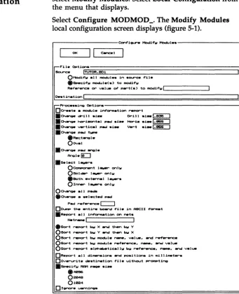
Chapter 5: Modify Modules ... 247
Execution ... 247 Local configuration ... 248 File Options ... 249 Processing Options ... 251 Example ... 255 Changing the shape of a pin on each module ... ~ ... 255
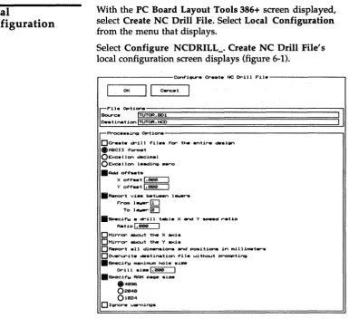
Chapter 6: Create NC Drill File ... 257
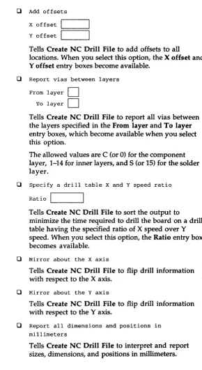
Execution ... 257 Local configuration ... 258 File Options ... 259 Processing Options ... 259 Examples ... 262 Drill size report ... 262 Conveying drill hole information to a drilling machine ... 262
Chapter 7: Reannotate Board File ... 263
Execution ... 263 Updating the schematic file ... 264
Local configura tion ... 265 File Options ... 266 Processing Options ... 268
Chapter 8: Fix Time Stamps ... 271
Execution ... 271 Local configuration ... 272 File Options ... 273 Processing Options ... 274
Part IV: Reporters ... 277
Chapter 9: Module Report ... 279
Execution ... 279 Local configuration ... 280 File Options ... 281 Processing Options ... 282 Examples ... 286 Show module text ... 286 Short report ... 286 Report by anchor point coordinates ... 286
Chapter 10: Compare Netlists ... 287
Execution ... 287 Local configura tion ... 288 File Options ... 288
Part V: Librarians ... 291
Chapter 11: Make Board Template ... 293
Execution ... 293 Local configura tion ... 294 File Options ... 294 Processing Options ... 294
Chapter 12: Make Library ... 295
PC Board Layout Tools 386+ Reference Guide
Part VI: Transfers ... 297
Chapter 13: To Schematic ... 299 Execution ... 299 Local configuration of To Schematic ... 300 Local configuration of BACKANNO ... 301 File Options ... 301 Processing Options ... 302
Chapter 14: To PLD ... 303
Execution ... 303
Chapter 15: To Digital Simulation ... 305
Execution ... 305
Chapter 16: To Maill ... 307
Execution ... 307
Appendixes ... 309
Appendix A: Command line controls ... 311
Syntax ... 311 About switches ... 311 Command files ... 312 COMPNET _ ... 314 FIXTIME_ ... 316 MAKE_T ... 318 MAKELIB ... 318 MODLOC_ ... 319 MODMOD_ ... 323 NCDRILL_ ... 327 PCB386 ... 329 REANN 0 _ ... 330
Glossary ... 333
Index ... 343
Finding the
information you
need
Installation
OrCAD's PC Board Layout Tools 386+ operates within the ESP design environment, which provides many features that make it easier to access and use OrCAD's electronic design automation (EDA) tool sets.
This book is a reference guide to PC Board Layout Tools 386+, the tool set used to layout printed circuit boards. See the ESP Design Environment User's Guide for detailed information about how to use OrCAD tools and tool sets in the ESP design environment.
These manuals accompany PC Board Layout Tools 386+:
.:. Installation & Technical Support Guide
.:. ESP Design Environment User's Guide
.:. Fast Track, a quick reference for
OrCAD /PCB II users upgrading to PCB 386+
.:. PC Board Layout Tools 386+ User's Guide
.:. PC Board Layout Tools 386+ Reference Guide
.:. Stony Brook M2EDIT Text Editor User's Guide
Before you begin to explore the software, take a few minutes to install the tool set and register for technical support. Just follow the instructions in the Installation &
Technical Support Guide that accompanies PC Board Layout Tools 386+.
PC Board Layout Tools 386+ Reference Guide
xxvi
About this guide
Other OrCAD publications
This reference guide helps you learn how to use PC Board Layout Tools 386+ with the ESP design environment to lay out printed circuit boards.
The first six parts of this guide are organized according to function. Each tool is described in one of these parts:
.:. Part I: Configuration
.:. Part II: Editors
.:. Part III: Processors
.:. Part IV: Reporters
.:. Part V: Librarians
.:. Part VI: Transfers
For example, to find information about Edit Layout, look in
Part II: Editors.
At the end of the guide, Appendix A provides additional information about running the tools from the command line.
A glossary and index follow Appendix A.
Some types of information change more rapidly than the manuals do, so OreAD publishes frequently changing information separately in technical notes and other documents.
Tool sets and tools
A tool set is a collection of tools designed to perform a set ofEDA tasks. Buttons that provide access to all four DreAD
tool sets display on the main screen, even if you only have one tool set installed on your computer. DrCAD's tool sets are:
.:. Schematic Design Tools
.:. Digital Simulation Tools
.:. Programmable Logic Design Tools
.:. PC Board Layout Tools
The tool sets manipulate the same design in different ways.
To select the PC Board Layout Tools 386+ tool set from the main design environment screen, move the pointer to the PC Board Layout Tools button and double-click. After a moment, you see the PC Board Layout Tools 386+ screen shown in the following figure.
PC Board Lawout Tool .. TUTOR o-i~ ESP Vx.xx .--- Edi tor .. - ,...--PI"'C>C_.or. - . - T r _ f ' ...
-To
Edit
EJ
ere.t .. l~~ .... tiC La!.jout Modul • • NC F i l . OrUI~ To
PLO
IEdit Fil .. 1
R • .nnotat. F1x
B~ 011;11t. 1mul.tior Board T1met
I To M.in I Vioow FU. S t _
R.f'er .. nc ..
,...--Libr.ri~ .. - .-R....",..t..-..- ...--US ...
-I U ... 1 Mak .. Mak ..
Modul ..
Board Librlll"'\ol Report T _ l a t .
. u. ... 2
, LJ.er 3
Cornp_ Netli .. t"
EJ
PC Board Layout Tools 386+ Reference Guide
xxviii
In tool sets, tools are grouped according to function. The six categories are:
.:. Librarians
.:. Processors .:. Transfers
.:. Reporters .:. User buttons
Editors Editors modify or create some part of the design database. An example of an editor is the board editor, Edit Layout. Another editor is Edit File, which uses a text editor to view reports and enter text. PC Board Layout Tools 386+ contains several editors, some contained within Edit Layout.
.:. Edit Layout is the board editor at the heart of PC Board Layout Tools 386+. In Edit Layout, you create and modify printed circuit boards. Edit Layout also includes the following editors:
• Library editor. Creates, loads, and modifies modules and module libraries.
• Pad symbol editor. Dialog box in which you define the shape, rotation, layer, and other aspects of the pad symbols used in the layout.
• Via symbol editor. Dialog box in which you define the layer, drill width, and other aspects of the via symbols used in the layout.
• Copper tool editor. Dialog box in which you define all aspects of the copper tools used to define the layout's attributes.
• Drill list editor. Dialog box in which you define the drill diameters used in the layout.
• Net property editor. Dialog box in which you define the copper tool, name, and other aspects of the nets used in the layout.
.:. Edit File runs a text editor, with which you create and edit text files .
PC Board Layout Tools 386+ Reference Guide
Processors
Reporters
xxx
Processors read, modify, then rewrite the design database. For example, Reannotate Board File is a processor.
Processors generally create or modify database information, and may also create reports. Processors may create data that will be used by tools outside the design environment.
PC Board Layout Tools 386+ includes the following processors:
.:. Modify Modules modifies pad shape, pad size, and drill size for modules in a board file .
• :. Create NC Drill File generates a file containing drilling information, including location and drill size, for a board file .
• :. Reannotate Board File reannotates your board file so the modules are numbered sequentially, according to their position on the board .
• :. Fix Time Stamps sets the time stamps that identify modules in your board file to match the corresponding time stamps in a netlist file.
Reporters create reports, but do not modify design data in any way. Reporters may create reports that will be used by tools outside the design environment. PC Board Layout Tools 386+ has two reporters:
.:. Module Report reports module locations in your board file .
Librarians
Transfers
User buttons
Librarians are tools for managing and creating library objects that can be used by all designs, not just the current design. PC Board Layout Tools 386+ includes two librarians:
.:. Make Board Template creates a template (a "starting point" for new board layouts or libraries) from a
PC Board Layout Tools 386+ board file .
• :. Make Library creates a library file from a PC Board Layout Tools 386+ board file.
Transfer tools manage the steps needed to move design information from one tool set to another. A transfer may modify the design database or simply transfer control to another tool set.
PC Board Layout Tools 386+ has four transfers: To Schematic, To PLD, To Digital Simulation, and To Main. Each of these transfers control to the specified tool set. For example, the To PLD transfer tool transfers control to the Programmable Logic Design Tools tool set.
A user button can be set up to run any system command or any .EXE, .COM, or .BAT file. A user button is the simplest way in which the ESP design environment can be extended to fit your particular requirements and make your work easier and more convenient.
PC Board Layout Tools 386+ Reference Guide
Conventions
The conventions used in this guide are as follows:Bold Bold indicates a command.
C ou r i e r b old Bold monospace indicates text you enter exactly as shown.
Italics
<B>
"Prompt"
Italics indicate a reference to another section or chapter of this guide or to another publication.
Angle brackets enclose a key that you press. For example, <Esc> indicates the escape key.
Quotation marks indicate program prompts and messages.
"Enter" and "type" In OrCAD manuals, the terms "enter" and "type" mean two different things. When the instructions tell you to enter
something, press the appropriate keys and end by pressing <Enter>. When the instructions tell you to type something, press the appropriate keys but do not press <Enter>.
xxxii
Boxes The box shown below represents a system prompt. Any bold type following the prompt indicates text that you enter.
Ie:>
orcadA box like the one shown at right represents an OrCAD menu.
A box like the one shown below represents a text entry box. Entry boxes appear on configuration
Execute
Local Configuration Assign Hot Key Configure ESP Help
screens, and can be empty or contain information you can edit.
Wildcard I~*_._*
________________________________
~6
NOTE: Notes contain important reminders or hints .About entry boxes You use all the entry boxes in the ESP design environment in the same way:
.:. Place the pointer inside the box and press <Enter> to enter insert mode. The pointer changes shape to become an underline cursor (_). In insert mode, the characters you type are inserted in any existing text at the point the cursor marks .
• :. To change to overtype mode, press <Insert>. The cursor becomes a square (.). In overtype mode, the characters you type replace any characters already there. You can toggle between insert and overtype modes as needed .
• :. Press <Enter> again to leave the entry box. The cursor is replaced by the pointer.
You can also use the editing keys on your keyboard to move around the entry box and edit its contents:
.:. <Home> moves the cursor to the beginning of the entry
box .
• :. <End> moves the cursor to the end of the entry box .
• :. The arrow keys <~> and <~> move right and left one character at a time, without erasing what you typed .
• :. <Backspace> backs up one character and deletes it.
.:. <Del> erases the character at the cursor's position without moving the cursor .
• :. The <Ctrl><Del> combination deletes the entire contents of the entry box .
• :. <Esc> aborts any changes to the entry box and changes the cursor back to a pointer.
PC Board Layout Tools 386+ Reference Guide
Mouse techniques
Left and right mouse buttons
xxxiv
You can do all your work in the ESP design environment (except typing text and numbers) using the mouse.
You point to an object by moving the pointer until the tip of the arrow touches the object. Do this by moving the mouse.
You select an object by pointing to it and clicking (pressing and then releasing) the left mouse button once. When you select a button, it becomes highlighted and a menu pops up in the upper-left corner of the screen .
• :. Clicking the left mouse button is the same as pressing the <Enter> key. In OrCAD guides, when you are instructed to press <Enter>, you can either press the <Enter> key or click the left mouse button .
• :. Clicking the right mouse button is the same as pressing the <Esc> key. In OrCAD guides, when you are
Keyboard
equivalents
Many of the explanations and instructions in this book use the mouse terminology explained on the previous page. If
you prefer to use the keyboard, however, there are keyboard equivalents to nearly every mouse operation. Instead of moving the mouse to move the pointer from button to button, you can:
.:. Press <Tab> to move the pointer to the first button in the next area on a tool set screen or, on configuration screens, to the next entry box .
• :. Press <Shift><Tab> to move the pointer backwards to the first button in the previous area .
• :. Press the <Space bar >to move the pointer from button to button within a group of tools, a set of radio buttons, or the scroll buttons associated with a list box .
• :. Press <Enter> to select the item the pointer rests on .
• :. Press <Home> to move the pointer to the first button in the area nearest the upper-left corner of the screen or, on configuration screens, to the OK button .
• :. Press <End> to move the pointer to the first user button or, on configuration screens, to the last button in the last area .
• :. Press <Esc> to close a menu without selecting any of the commands or to cancel any changes to a text entry box .
• :. Press <Page Up> and <Page Down> to pan up and down on configuration screens.
PC Board Layout Tools 386+ Reference Guide
Configuration
screens
xxxvi
About ".\" in pathnames
PrefiX/Wildcard entry boxes
PC Board Layout Tools 386+ and the ESP design environment have many configuration screens. Some
configuration screens apply only to a specific tool. These are called local configuration screens. Other configuration screens-such as the Configure PC Board Layout screen-are global in nature.
Many configuration screens have entry boxes that specify path and filenames. Labels for these entry boxes include PrefixlWildcard, Source, and Destination.
When you specify a pathname, you can use a period and a backslash (. \) as a convenient shortcut to specify the current design directory. For example, if the current design is TEMPLATE, then ".\ *.MLB" means all files in the \ORCAD\TEMPLATE directory that have a .MLB extension.
Many configuration screens have a PrefixIWildcard entry box. These entry boxes contain a pathname and possibly a filename with a wildcard to indicate which files to display in a list box. The asterisk can be used as a wildcard in a filename. This example lists all files in the
C:\ORCADESP\PCB\LIBRARY path that have a .MLB extension:
List boxes
Filename entry boxes
Many configuration screens have list boxes containing lists of items from which to choose. Be sure you know how to select an item from a list box and how to use the scroll bars to scroll the item lists. Items with ". \" are found in the current design directory. Items without 1/. \ " are found in the path given in the PrefixIWildcard entry box. When you place the pointer on a filename in a list box and select <Enter> or click the left mouse button on a filename in a list box, the item automatically displays in the related entry box.
Most local configuration screens have a Source entry box. Many have other filename entry boxes as well.
The first time you display a local configuration screen, its Source and Destination entry boxes contain-where appropriate-the name of the root sheet (specified in Design Management Tools) followed by a default extension. You can, however, change this to suit your needs.
If you change the filename extension in the Source entry box, when you select OK to leave the configuration screen and save the changes, the extension in the PrefiX/Wildcard entry box also automatically changes to the same extension.
On many configuration screens, you can use a question mark (?) as a shorthand notation for the name of the root sheet. For example, if the current root sheet is TUTOR and you enter? • MLB, the ESP design environment interprets the I/?" as "TUTOR" when you select OK to leave the configuration screen and save your changes. See the section
Using Design View in Chapter 2: Using Design Management Tools of the ESP Design Environment User's Guide for a description of the root sheet and how it controls filenames in configuration screens.
When you install PC Board Layout Tools 386+ on your system's hard disk, it is configured and ready to run.
Part I: Configuration explains how to customize your PC Board Layout Tools 386+ configuration.
Chapter 1: Configure Layout Tools describes how to modify:
.:.
Driver options.:.
Library options.:
.
Prefix options.
:.
Filter options.:.
Virtual memory optionsConfigure Lay ou
t
To
0
Is
The ESP design environment has three types of configur-ation, all of which customize and save information used to run OrCAD tools and tool sets .
• :. ESP design environment configuration defines driver options, the text editor, the startup design, and monitor display colors. Although the ESP design environment is already configured when installed, you can change the ESP design environment parameters whenever you want.
The ESP Design Environment User's Guide provides detailed instructions for customizing the ESP design environment.
.:. Tool set configuration defines library, filename, and other tool set-specific options. Tool set configuration applies to all tools in a tool set and can be changed from every tool in the tool set except transfers and user buttons. It has a default configuration when installed but can also be changed anytime you want to change the tool set parameters.
PC Board Layout Tools 386+ Reference Guide
4
.:. Local configuration determines input and output files and special processing options for a particular tool. If a tool runs several processes, each process can be locally configured.
Local configuration is set up with input and output filenames defaulting to the design name in most cases. You usually configure a tool when you begin work on a design, or anytime you want to change the tool's parameters.
Display the
Configure Layout
Tools screen
With the PC Board Layout Tools 386+ screen displayed, select any of the editors, processors, librarians, or reporters. For example, select Edit Layout.
The menu shown at right displays at the top of the screen. Select Configure Layout Tools. Each area on the Configure PC Board Layout screen is shown in the sections that follow.
Execute
Local Configuration Assign Hot Key Show Version
Configure Layout Tools Help
The Configure PC Board Layout screen contains more information than can fit on the display screen at one time. You can think of your display screen as a "window" onto the Configure PC Board Layout screen. Move the pointer down until it touches the lower edge of the display, and the display pans, moving the window to show more options.
If you prefer to use keyboard commands, press <Page Down> to move the window down part of a screen at a time, and <Page Up> to go up again. Press <End> to go to the bottom of the screen and <Home> to return to the top again.
In various places within the configuration screen, there are boxes in which lists (usually of files) display. Using the scroll buttons to the right of each list box, you can move these lists up and down in a manner similar to the scrolling process used for the Configure PC Board Layout screen.
When you finish making changes, select OK to save your changes and return to the PC Board Layout Tools screen. If
PC Board Layout Tools 386+ Reference Guide
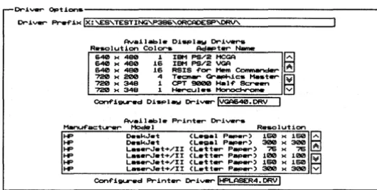
Driver Options
6
The Driver Options area (figure 1-1) defines the driver prefix and the display and printer drivers. These are described in this section.
Cr~v.r Opt~on.---~
Cr~ver- ~ ~>< Ix: '-ES'TESTING'P38E>'ORCAOESP'ORV' Ava~labl. O~_law Cr~veNi RlHK>lution Colora Ac:I . . t..,... Name
D<4C!I )( _ 1 IBM PS/2 MeGA B
~
=:=
f~:::9 ~~=
Comonandet-~ ~=
=
1 ~~='i'!-c~""" iii720 )( 348 1 Hercul • • tloo ooc:I • ...- E1
Conf'iilll'ed O~tlPlaw Or-i ... !VGAD<4C!l.ORV !
Av.ilabl .. Print ... Or-ivers
Menuf'act.,...,.. Mode I Rotso I ut ion
HP OotskJ_t CL. . . . I P _ r ) 150 >< 150 ~ HP o . . k J . t CL. . . . 1 P _ r ) 300 >< 300 HP L. _ _ r J . t + / I I CL..1:t..,... p ... > 75 >< 75 A HP L._.rJ.t+/II CL..1:t..,... Pap..,...> 100 >< 100 ~ HP L.-...J.t+/II CL..1:t..,... Peper> 150 )( 150 HP L. ... r.J .. t+/II CL. .. 1:t .... P ... > 300 )( 300 V
[image:45.507.178.448.115.251.2]Conf'i~ Print..,... Or-i" ... !HPl...ASER4.0RV!
Figure 1-1. Driver Options area of the Configure PC Board Layout
Driver Prefix
Example
The Driver Prefix is the directory path or disk drive where PC Board Layout Tools 386+ finds and loads the display and printer drivers.
The driver prefix is set during the installation process and does not need to change unless you move drivers to a
different directory or create custom drivers in another directory.
To define the driver prefix, enter the pathname of the directory containing your device drivers.
Once you enter a driver prefix, all drivers in that directory display in the appropriate list boxes: Available Display Drivers, Available Printer Drivers, and Available Plotter Drivers. Each of these list boxes is described in the sections that follow.
NOTE: Only the drivers that are recognized by name appear in the list boxes. Custom drivers do not appear, and their names need to be typed into the entry boxes.
The default Driver Prefix is defined during the installation process. If you installed PC Board Layout Tools 386+ on your C drive, the prefix is:
Driver Prefix IC:\ORCADESP\DRV\
PC Board Layout Tools 386+ Reference Guide
8
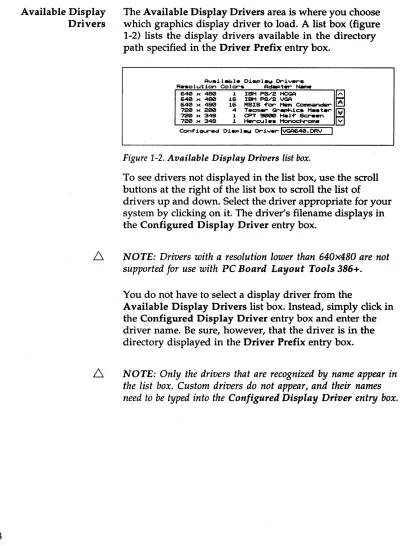
Available Display Drivers
The Available Display Drivers area is where you choose which graphics display driver to load. A list box (figure 1-2) lists the display drivers available in the directory path specified in the Driver Prefix entry box.
Av.i I_Ie Displ.w Driver'S Re.olution Colors Ad~ter- N.m.
640 x 480 1 IBM PS/2 HCGA
B
~ ~ ~= ~~ ~~S ~~
=
eornr-ncler ~720 x 200 4 TecmW" Gr~ic. H..ter- ~
720 )( 348 1 CPT 9000 Ha I-f" Screen
[image:47.504.56.458.62.608.2]720 x 348 1 Httrcu Ie. l'1onoc:hrorne v Con-f"iQUred Di.plaw DriverIVGA640.DRV I
Figure 1-2. Available Display Drivers list box.
To see drivers not displayed in the list box, use the scroll buttons at the right of the list box to scroll the list of drivers up and down. Select the driver appropriate for your system by clicking on it. The driver's filename displays in the Configured Display Driver entry box.
6
NOTE: Drivers with a resolution lower than 640x480 are not supported for use with PC Board Layout Tools 386+.You do not have to select a display driver from the
Available Display Drivers list box. Instead, simply click in the Configured Display Driver entry box and enter the driver name. Be sure, however, that the driver is in the directory displayed in the Driver Prefix entry box.
Example
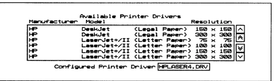
Available Printer Drivers
Example
If you select IBM PS/2 VGA from the drivers displayed in figure 1-2, the following displays:
Conf igured Di splay Driver 1 - 1 V_G_A_6_4_0_._D_RV _ _ _ _ _ _ - - - - l
NOTE: If a driver is not configured here, PC Board Layout Tools 386+ uses the one selected during installation.
The Available Printer Drivers area of the screen is where you choose which printer driver to load. A list box (figure 1-3) lists the printer drivers available in the directory path specified in the Driver Prefix entry box.
Availabl. Printer Drivers
~acturer Medel R.solution
I-P o..kJ.t (L.gal P ... r) 160 >< 150 ~
I-P o..kJ.t (L.gal P .... er) 300 >< 300
I-P L • • erJet+/II (Letter Paper) 75 >< 75 A
I-P L • • erJet+/II (Letter Paper) 100 >< 100 ~
HP Le~erJet+/II (Letter Paper) 160 >< 160 W
[image:48.504.176.447.245.326.2]I-P L • • erJet+/II (Letter Paper) 300 >< 300 v C~igur.d Printer DriverIHPLASER4.DRVI
Figure 1-3. Available Printer Drivers list box.
Select the driver appropriate for your printer. Its filename displays in the Configured Printer Driver entry box.
You can also enter the driver name in the Configured Printer Driver entry box. Be sure, however, that the driver is in the directory displayed in the Driver Prefix entry box.
NOTE: Only the drivers that are recognized by name appear in the list box. Custom drivers do not appear, and their names need to be typed into the Configured Printer Driver entry box.
If you select LaserJet+/II (Letter Paper) 300 x 300 from the drivers displayed in figure 1-3, the following displays:
PC Board Layout Tools 386+ Reference Guide
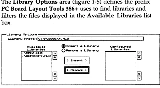
Library Options
Library Prefix
10
The Library Options area (figure 1-5) defines the prefix PC Board Layout Tools 386+ uses to find libraries and filters the files displayed in the Available Libraries list box.
. I n ... t _ Li ... arw
QRotmCNe _ Li ... arw
I> In ... t > I
[image:49.504.182.459.71.223.2]IE R eEl
Figure 1 .. :5. Library Options area of the Configure PC Board Layout screen.
To define the Library Prefix, enter the pathname of the directory containing your module libraries followed by a filename or wildcard, such as *.MLB.
This example tells PC Board Layout Tools 386+ to
display the names of all files with a .MLB extension in the \ORCADESP\PCB\LIBRARY directory on the C drive:
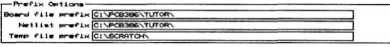
Prefix Options
Board file prefix
N etlist prefix
The Prefix Options area (figure 1-6) defines where PC Board Layout Tools 386+ finds board files and netlist files and where it creates temporary files.
f'I-.. f'.i.>< Opticns.-:-;;;:;:;;;;;;:;:;;;;;::====================:::;--I
ec..rc:l f'il .. -f'i)(li§le~:~~B~3BG~'=:i:T~UT§.OR§"===========~ NRtlist _f'i><le:~'TUTOR'
T • ..., f'11. _f'i>< Ie:
'-SCRATCH'-Figure 1-6. Prefix Options area of the Configure PC Board Layout
screen.
If you are using the standard OrCAD directory structure, this entry box should be blank:
Board file prefix LI _ _ _ _ _ _ _ _ _ _ _ _ _ ---l
If you are not using the standard OrCAD directory structure, enter the path to the directory containing your board file. This example tells PC Board Layout Tools 386+ to look for the file in the \ORCADESP\PCB\BOARDS directory:
Board file prefix I\ORCADESP\PCB\BOARDS\
If you are using the standard OrCAD directory structure, this entry box should be blank:
Netl ist prefix 1 - 1 ______________---1
If you are not using the standard OrCAD directory structure, enter the path to the directory containing your netlist files. This example tells PC Board Layout Tools 386+ to look for netlists in the \ORCADESP\PCB\NETLIST directory:
[image:50.505.173.448.117.150.2]PC Board Layout Tools 386+ Reference Guide
12
Temp file prefix Enter the path to a drive and directory where PC Board Layout Tools 386+ can create temporary files. This example tells PC Board Layout Tools 386+ to create temporary files in the \SCRATCH directory on drive C:
Temp f i le prefix 1 - 1 C_:_\_SC_R_A_T_C_H\ _ _ _ _ _ _ _ _ _ --'
As you work, PC Board Layout Tools 386+ may create many different temporary files. To be sure you have enough room for these files, you should have about five times as much available disk space as the size of your largest board file. For example, if your largest board file is 2 MB, you should have at least 10 MB free disk space.
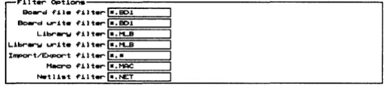
Filter Options
Board file filter
Board write filter
Library filter
Library write filter
[image:52.505.173.452.108.171.2]The Filter Options area (figure 1-7) defines what files Edit Layout lists in various dialog boxes.
Figure 1-7. Filter Options area of the Configure PC Board Layout
screen.
Enter the files to list in the dialog box that displays when you load a board file. This example tells Edit Layout to list all files with a .BOI extension:
Board file filter 1L-*_._B_D_l _ _ ---'
Enter the files to list in the dialog box that displays when you write out a board file. This example tells Edit Layout to list all files with a .BOI extension:
Board write filter , - I *_._B_D_l _ _ ---'
Enter the files to list in the dialog box that displays when you load a library file. This example tells Edit Layout to list all files with a .MLB extension:
Library filter , - I *_._M_L_B _ _ ---'
Enter the files to list in the dialog box that displays when you write out a library file. This example tells Edit Layout to list all files with a .MLB extension:
PC Board Layout Tools 386+ Reference Guide
Import/Export filter
Macro filter
Netlist filter
14
Enter the files to list in the dialog box that displays when you import or export a pad symbol, via symbol, copper tool, or drill list. This example tells Edit Layout to list all files:
Import/Export filter
I
...
*_._* _ _ _ ~Enter the files to list in the dialog box that displays when you load or save a macro. This example tells Edit Layout to list all files with a .MAC extension:
Macro filter L - I *_._M_A_C _ _ - - J
Enter the files to list in the dialog box that displays when you load a netlist. This example tells Edit Layout to list all files with a .NET extension:
Virtual
Memory
Options
Directory
The Virtual Memory Options area (figure 1-8) is where you specify the directory where the Phar Lap memory extender can create a swap file and the filename it should use.
E
VJ..-1:Ual ... 1nOI"'W optJ.."...,. DJ.,...c:to.-w Ie:,FUe ig:;LSHAI~IAF'F"==IL.E====. T l ' 1 P : = i I - - - '
Figure 1-8. Virtual Memory Options area of the Configure
PC Board Layout screen.
You should have about one and a half (1.5) times as much available disk space as the amount of RAM installed on your system. For example, if your system has 8 MB of RAM, you should have 12 MB available disk space for use by the Phar Lap memory extender.
See the PC Board Layout Tools 386+ User's Guide for a description of the Phar Lap memory extender.
Enter the path to a drive and directory where the PharLap memory extender can create a swap file. This example tells PC Board Layout Tools 386+ to create the file in the SWAPDIR directory on drive C:
Directory IC:\SWAPDIR
File Enter the name of the swap file to be created by the Phar Lap memory extender. The file will be created in the directory specified in the Directory entry box:
File ISWAPFILE.TMPI
Note that the swap file is deleted when PC Board Layout Tools 386+ exits normally. If for some reason the specified swap file is not deleted, however, the memory extender will fail when you next run PC Board Layout Tools 386+.
You can make sure the swap file is deleted by adding a line to your AUTOEXEC.BAT file. The line should look
something like this:
PC Board Layout Tools 386+ Reference Guide
Miscellaneous
Options
Template
16
The Miscellaneous Options area (figure 1-9) is where you specify the template file to load.
Figure 1-9. Miscellaneous Options area of the Configure PC Board Layout screen.
ORCADPCB._T_ is the template file provided with PC Board Layout Tools 386+. ORCADPCB._T_ serves as the template board file and the template library file. You can create as many template files as you like to meet your needs.
Enter the name of the template file. You can also specify a relative or absolute path to the file. See Chapter 2: Edit Layout for information about absolute and relative pathnames as they pertain to template files.
In this example, the absolute pathname tells Edit Layout exactly where to look for the template file:
PC Board Layout Tools 386+ includes editors that you use to create and modify board files and library files, edit text files, and view files containing reference information.
Part II: Editors describes editors and provides instructions for their use.
Chapter 2:
Chapter 3:
Chapter 4:
Edit Layout describes how to configure Edit Layout and provides an alphabetical reference to the procedures, concepts, commands, menus, and dialog boxes of Edit Layout.
Edit File describes how to use Edit File to run the text editor of your choice.
Edit Layout
Execution
This chapter contains information needed to use Edit Layout, the board editor at the heart of PC Board Layout Tools 386+.
In this chapter, information on execution and local configuration is followed by descriptions of Edit Layout commands and concepts. These entries are listed in alphabetical order.
With the PC Board Layout Tools screen displayed, select Edit Layout. Select Execute from the menu that displays.
If you have not specified a board file, Edit Layout loadS the template named in the Miscellaneous Options area of the Configure Layout Tools screen.
PC Board Layout Tools 386+ Reference Guide
Local
configuration
With the PC Board Layout Tools screen displayed, select Edit Layout. Select Local Configuration from the menu that displays.
Select Configure PCB386. Edit Layout's local configuration screen displays.
Conf'i... Edi t LAwout
I
OKII
CIInC.lI
- I ' " i l . Opti.",. Pref'ix/I-lildc ... d 1 •• eD1
Fil • •
r'=Mom,
I:
Sour-c·ITUTOR.eD1 I IcProc ... i~ OptJ..",. ..QL .. f't hand ....,... ."....r.tion
I
I
File Options The File Options area defines the source board file.
20
Prefix/Wildcard PrefiX/Wildcard contains a path to the directory that contains the board file you want to edit and a filter that controls the files displayed in the Files list box. For example, the following entry displays all files with a .BOI extension in the \ORCAO\ TUTOR directory on drive C:
Prefix/Wildcard IC:\ORCAD\TUTOR\*.BDl
PrefixIWildcard entry boxes are described in the ESP Design Environment User's Guide.
Files
Source
Processing Options
Reference
This box contains a list of files that match the path and filter specified in the PrefixIWildcard entry box and files in the current design directory that match the wildcard. Files in the current design directory have ". \" before their names. The filename you select in this list box displays in the Source entry box.
Source is the name of the PC Board Layout Tools 386+ board file to load. It may have any valid pathname. The source is originally set to rootSheet.BD1.
If you do not specify a source file, Edit Layout displays a notice and loads the template file. For more information see Chapter 1: Configure Layout Tools in this manual and the entries Template files and Configuring template files in this chapter.
o
Left hand mouse operationTells Edit Layout to reverse the functions «Enter> and <Esc» of the mouse buttons. Select Left hand mouse operation again to disable this option and return the mouse buttons to their standard functions.
The remainder of this chapter is a reference for Edit Layout, the board and library editor. Procedures, concepts, commands, menus, and dialog boxes are described in alphabetical order.
PC Board Layout Tools 386+ Reference Guide
Abandon Program
command
About button
About dialog box
Add button
On the Edit Net Properties dialog box
Alignment Target
command
22
Appears on the board editor QUIT menu.
Exits Edit Layout and displays the PC Board Layout Tools 386+ screen.
NOTE: Abandon Program does not save edits to the board file currently loaded, nor does it prompt you to save edits before exiting Edit Layout. Make sure you update your board file with QUIT Update Board File before you select QUIT Abandon Program.
Appears on the Global Options and Conditions dialog boxes.
Displays the About dialog box.
Shows the program name, version number, release date, and copyright information.
r---~t---~
~
Appears on a number of dialog boxes.
In most cases, Add adds an item shown in an entry box to the corresponding list.
Applies all properties as marked (selected, entered, or enabled/ disabled), regardless of the state of the corresponding Apply to ALL Nets check box, to the net whose name appears in the entry box below the Net Names list box.
Appears on the PLACE menu.
Loads the current alignment target settings.
All command
Append button
Apply to ALL
button
Area Autoroute
command
Appears on the Delete Block menu.
Deletes all of the objects within or intersected by the block boundary.
Appears on a number of dialog boxes.
Adds an item to the bottom of a list box.
Appears on the Edit Net Properties dialog box.
For each Apply to All Nets check box that is enabled, Apply to All applies the corresponding property as marked (selected, entered, or enabled/disabled) to all nets.
Appears on the Block End menu that displays when you define the lower right corner of the autoroute block boundary.
Automatically routes the block; however, if an autoroute zone is defined which does not encompass the entire block, the autorouter routes only the autoroute zone.
PC Board Layout Tools 386+ Reference Guide
Assigning nets to
fill zones
Assigning nets to
pads
24
1. Place the pointer on one of the fill zone outline segments and select EDIT. The Edit Zone Segment dialog box displays.
2. Select Zone Properties. The Edit Zone Properties dialog box displays.
3. Select a net from the Net Names list box, and then select OK.
4. Select Cancel to close the Edit Zone Segment dialog box.
If you manually place modules on the board, you have to assign nets to each pad.
1. Make sure that Allow Edits Of Module Objects and Allow Module Delete are enabled in the Global Options dialog box.
2. Place the pointer on the desired pad and select EDIT. The Edit Pad dialog box displays.
3. Select an existing net name in the Net Names list box, or enter a new net name in the entry box directly beneath the list box.
Autoroute
Options
dialog box
Autoroute Method
Use this dialog box to set the autoroute methods.
, - - - A u t o r - o u t . Options - - - ,
c:E:]'C...:.1 "Clob.1 ,
Autorout. I'Wtl-lod .Stancia'-d
Ol'lortftor-w
OMaze Onlw OMa)(i .... 1
OMini .... 1
OPr.f' ... d Oi ... .ction O D 1 _ 1 o n OVi. Reduction ODelete PRC Viol.ti ...
SUetIp Routine Di .... ct1on .Up. L.ef't ODol.ln, L.ef't ORight. Up OL...,.t. Up OUp. Right ODol.ln. Right ORight. DoI.In ~ OL...,.t. DoI.In
DF" •• t Routine
Fast Routing Enable to run the autorouter in fast routing mode. This turns off full shoving and allows shoves to occur for vias only.
Note that autorouting is much faster when Fast Routing is enabled, but the autorouter may complete fewer connections and use more vias and greater wire length.
Standard Autoroutes in two passes: first by the memory method, then by the maze method.
Memory Autoroutes from pad to pad in the preferred .~
direction, if there is nothing between the pads or if there is only one pad (on another net) between the pads.
Maze only Use to autoroute all connections.
Maximal Use to autoroute the remaining connections not completed by other methods. This method has more
freedom to insert vias and find meandering paths, but takes longer.
PC Board Layout Tools 386+ Reference Guide
26
Sweep Routing Direction
Preferred Direction Only performs maze routing in the
preferred direction. If necessary, it allows routing up to two grid spaces in the non preferred direction.
Dispersion Enables any surface mounted pad to get to
internal layers by attaching a stub and via to the pad. Primarily used to connect to power and ground planes.
Via Reduction Reroutes connections with vias in an
attempt to decrease the number of vias. Best used after routing is complete.
Delete ORe Violations Goes through the board and
deletes one (chosen arbitrarily) of the two objects that together create a spacing violation.
Use to specify the primary and secondary directions for the sweep routing window. The default selection is Up, Left. This causes the sweep window to move up from the starting location to the top of the board, then down from the
starting location to the bottom of the board; then shift left and repeat the process (starting location to top, starting location to bottom), shifting left until it reaches the left edge of the board; then shift to the right of the starting location and repeat the process (starting location to top, starting location to bottom), shifting right until it reaches the right edge.
To take advantage of this feature, draw the sweep window boundary around the densest area on the board so it is routed first, and select the routing direction that moves the sweep window to the next densest area.
In the example at right, density is represented by the darkness of the shading. Draw the starting sweep window around the densest area, above and to the left of center, so this area will be routed first. Select Down, Right so the sweep window will move in the direction indicated by the numbers.
Autoroute Whole
Board command
Autoroute Zone
command
Autoroute zones
A