University of Warwick institutional repository: http://go.warwick.ac.uk/wrap
A Thesis Submitted for the Degree of PhD at the University of Warwick
http://go.warwick.ac.uk/wrap/36892
This thesis is made available online and is protected by original copyright. Please scroll down to view the document itself.
Innovation Report
A
UTOCODING
M
ETHODS FOR
N
ETWORKED
E
MBEDDED
S
YSTEMS
Submitted in partial fulfilment of the Engineering Doctorate
By James Finney, 0117868
November 2009
Declaration
I have read and understood the rules on cheating, plagiarism and appropriate referencing
as outlined in my handbook and I declare that the work contained in this submission is
my own, unless otherwise acknowledged.
Acknowledgements
I would like to thank Rapicore Ltd and the EPSRC for funding this project. I would also
like to offer special thanks to my supervisors: Dr. R.P. Jones, Dr. P. Faithfull, and R.
Table of Contents
Declaration ... ii
Acknowledgements ... iii
Figures ... vi
Tables ... vi
Definitions & Abbreviations ... vii
Abstract ... viii
1. Introduction ... 1
1.1. Background ... 1
1.1.1. Autocoding CASE tools ... 3
1.1.2. NetGen ... 8
1.2. Research Aim and Methodology ... 11
1.2.1. Research Aim ... 11
1.2.2. Research Methodology ... 12
1.3. Portfolio and Innovation Report Structure ... 15
1.3.1. Portfolio Structure ... 15
1.3.2. Innovation Report Structure ... 17
2. Literature Review ... 18
2.1. Autocoding Options ... 19
2.1.1. Model-Based Design and Autocoding Tool Review ... 20
2.1.2. Network Design and Autocoding Tool Review ... 21
2.1.3. Findings ... 22
2.2. Autocoding Methods ... 25
2.2.1. Code Template Implementations ... 27
2.2.2. Autocoder Front-Ends ... 28
2.2.3. Processing ... 30
2.3. Summary ... 33
2.3.1. Model-Based Design and Autocoding Tools ... 33
2.3.2. Network Design Tools ... 35
2.3.3. Autocoding Methods ... 36
3. NetGen Analysis ... 38
3.1. CAN Project ... 39
3.1.1. Aims ... 39
3.1.2. Results ... 39
3.2. FlexRay Project ... 41
3.2.1. Aims ... 41
3.2.2. Results ... 42
3.3 Recommendations ... 43
3.3.1. Autocoding Method ... 43
3.3.2. Autocoding Options ... 44
4. Prototype Platform Research and Development... 46
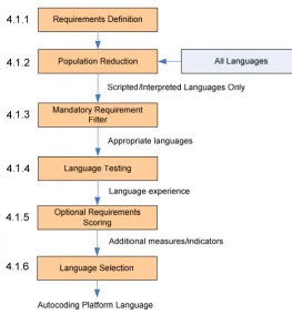
4.1. Language Research and Selection ... 47
4.1.1. Requirements Definition ... 47
4.1.4. Language Testing ... 50
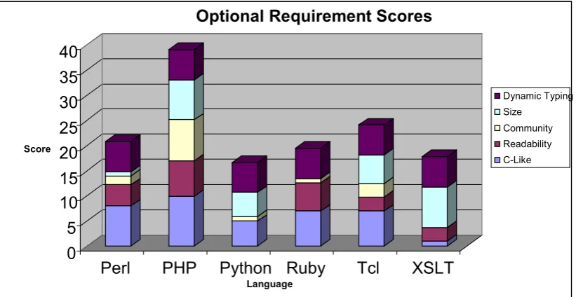
4.1.5. Optional Requirements Scoring ... 52
4.1.6. Language Selection ... 53
4.2. Autocoding Platform Development ... 56
4.2.1. Development Model ... 57
4.2.2. Requirements Analysis ... 59
4.2.3. System Design ... 60
4.2.4. Architectural Design ... 63
4.2.5. Module Design ... 65
4.2.6. Implementation ... 66
4.2.7. Validation ... 74
5. Prototype Platform Evaluation ... 80
5.1. Evaluation Criteria ... 80
5.2. Case Study ... 81
5.3. Evaluation Results ... 83
6. Discussion ... 88
6.1. Claim of Innovation ... 89
6.2. Autocoding Method ... 89
6.2.1. Static Autocoding with XML Code Descriptions ... 90
6.2.2. Dynamic Autocoding with PHP ... 95
6.3. Innovation Justification ... 98
6.3.1. Successful Exploitation ... 98
6.3.2. Originality ... 100
6.4. Effects of Commercial Constraints ... 102
6.4.1. Capital Limitations ... 102
6.4.2. Resources ... 103
6.4.3. Market ... 104
6.5. Final Learning Outcomes ... 104
6.5.1. Peer Reviewing ... 104
6.5.2. Requirements Selection ... 105
6.5.3. Model Selection ... 105
6.5.4. Centralised Component Design ... 106
6.6. Impact of the Work ... 106
6.7. Limitations of the Work ... 108
7. Conclusion ... 110
8. Future Work ... 113
8.1. Short Term ... 113
8.2. Long Term ... 118
8.3. Activity Times ... 118
References ... 120
Appendices ... 124
Appendix A – MBD and autocoding tool comparison table ... 125
Appendix B – Mandatory requirement recordings ... 126
Appendix C – Autocoding test findings summary ... 128
Figures
Figure 1 – An autocoder and its various inputs and outputs ... 4
Figure 2 - Use of static and dynamic template types to generate source code ... 7
Figure 3 - NetGen Graphical User Interface ... 9
Figure 4 - XSLT document generation method ... 10
Figure 5 - Research Methodology diagram ... 13
Figure 6 - Portfolio structure, submissions, and reading order ... 15
Figure 7 – Mapping an input value to a COGENT parameter [32] ... 28
Figure 8 – Implementation of the design pattern tool [32] ... 29
Figure 9 – The CodeSmith Studio graphical user interface ... 29
Figure 10 - Overview of the TLC process ... 32
Figure 11 - Language selection Research Methodology ... 47
Figure 12 - Sample from the mandatory requirements recording spreadsheet ... 50
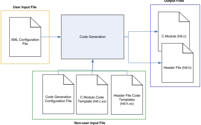
Figure 13 - Test code generation application input and output files. ... 51
Figure 14 - Cumulative optional requirement score graph ... 54
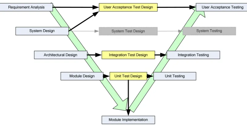
Figure 15 - The V-Model variant used for the autocoding platform’s development ... 58
Figure 16 - Abstract platform diagram of system inputs and outputs ... 60
Figure 17 - The Autocoding Platform's high-level (architectural) design ... 64
Figure 18 - An example UML class diagram for the Advanced Code Processor ... 65
Figure 19 - Main Window, Host, Information, and Command components ... 67
Figure 20 - Screenshot of Application Selection component's implementation ... 70
Figure 21 - Screenshot of Code Generation component's implementation ... 71
Figure 22 - Screenshot of formatting component's implementation ... 72
Figure 23 - Implemented Identifier Naming window... 74
Figure 24 - Abstract diagram of the evaluation software stack ... 83
Tables
Table 1 - Model-based design oriented autocoding tools reviewed ... 20Table 2 - Embedded network design and autocoding tools reviewed ... 22
Table 3 - Comparison of the MBD and autocoding tools reviewed ... 33
Table 4 - Mandatory and optional requirements for language selection ... 48
Table 5 - Scripted and interpreted languages for the next stage of research ... 49
Table 6 - Optional requirement weightings ... 52
Table 7 - Example of Technical User requirements capture spreadsheet ... 59
Table 8 - Autocoding platform software metrics summary... 66
Table 9 - Module Test Summary ... 75
Table 10 - Integration Test Summary ... 76
Table 11 - User Acceptance Tests Summary ... 77
Table 12 - Requirement fulfilment summary by stakeholder and requirement type ... 78
Table 13 - Mandatory requirements not fulfilled by the platform... 78
Table 14 - Prototype autocoding platform evaluation criteria... 81
Table 15 - Criteria and criteria satisfaction summary ... 84
Table 16 - Application metric comparisons ... 85
Table 17 - Autocoding method comparison table of pros and cons ... 87
Table 18 - Prototype autocoding platform benefits ... 99
Table 20 - Timescales for the future work activities ... 119
Definitions & Abbreviations
API Application Programming Interface
ASCII American Standard Code for Information Interchange
ASG Abstract Syntax Graph
ASP Active Server Pages
AST Abstract Syntax Tree
CA Controller Area Network
CASE Computer-Aided Software Engineering
CI Continuous Integration
COGE T COde GENeration Template
FIFO First-In-First-Out
FILO First-In-Last-Out
FlexRay High-speed automotive network communication protocol
GCC GNU Compiler Collection
Glade User Interface designer for the GTK+ toolkit
GTK+ Open-source toolkit for creating graphical user interfaces
GUI Graphical User Interface
HAL Hardware Abstraction Layer
HTML Hyper-text Mark-up Language
IEEE Institute of Electrical and Electronics Engineers
IP Intellectual Property
Intelli-sense Autocompletion implementation
JRE Java Runtime Environment
LI Local Interconnect Network
MBD Model-Based Design
MISRA Motor Industry Software Reliability Association
ATO North Atlantic Treaty Organisation
OEM Original Equipment Manufacturer
PHP PHP: Hyper-text Pre-processor
PHP-sat Static code analysis tool for PHP
PHPUnit Unit testing tool for PHP
SDF System Description File
TDMA Time Division Multiple Access
TLC Target Language Compiler
UAT User Acceptance Test
UML Unified Modelling Language
W3C World Wide Web Consortium
XML Extensible Mark-up Language
Abstract
The volume and complexity of software is increasing; presenting developers with an
ever increasing challenge to deliver a system within the agreed timescale and budget
[1]. With the use of Computer-Aided Software Engineering (CASE) tools for
requirements management, component design, and software validation the risks to the
project can be reduced. This project focuses on Autocoding CASE tools, the methods
used by such tools to generate the code, and the features these tools provide the user.
The Extensible Stylesheet Language Transformation (XSLT) based autocoding method
used by Rapicore in their NetGen embedded network design tool was known to have a
number of issues and limitations. The aim of the research was to identify these issues
and develop an innovative solution that would support current and future autocoding
requirements. Using the literature review and a number of practical projects, the issues
with the XSLT-based method were identified. These issues were used to define the
requirements with which a more appropriate autocoding method was researched and
developed. A more powerful language was researched and selected, and with this
language a prototype autocoding platform was designed, developed, validated, and
evaluated.
The work concludes that the innovative use and integration of programmer-level
Extensible Markup Language (XML) code descriptions and PHP scripting has provided
Rapicore with a powerful and flexible autocoding platform to support current and future
1.
Introduction
1.1. Background
The 1960s saw the start of the Software Crisis; a term coined by F. L. Bauer at the first
NATO Software Engineering Conference in Garmisch, Germany. The term referred to
the difficulty in writing correct, reliable and high quality software as computing power
rapidly increased [2].
Since the invention of the integrated circuit in 1958, the number of transistors has
increased exponentially; doubling approximately every two years. This trend was first
observed by Gordon E. Moore, founder of Intel in his 1965 paper [3]. As the power of
these devices increased, so too did the complexity of the problems and applications that
could be tackled. The complexity of the software used to control these devices also
grew through the increase in code volume, data, and control algorithm complexity
required in more advanced applications. The complexity of the software not only
challenged the developers in terms of designing, implementing, and validating the
software; but also had serious implications on the management of the project and
development process.
Through the increase in software complexity and the relative immaturity of software
engineering as a discipline at the time, the crisis manifested itself in a number of ways:
projects were unmanageable and therefore running over-budget and over-time; software
was inefficient, of low quality, difficult to maintain, and often did not meet the
The crisis encouraged software engineering research and resulted in a range of new
methodologies, processes, tools, and other related disciplines. Software Engineering
became more recognised as a discipline and is currently defined by the IEEE as the application of a systematic, disciplined, quantifiable approach to the development, operation, and maintenance of software, and the study of these approaches; that is, the
application of engineering to software [5].
One of the most significant outcomes from the research was the range of CASE tools
that can be used in projects to improve the reliability, quality, and speed of a software
development. These tools covered all stages of a typical software development process
such as: requirements capture; component design and simulation; software
implementation; system validation [6].
Although CASE tools have been used successfully in many industries, ranging from
automotive and aerospace to industrial and consumer; the continual increase in
computing power and application complexity is still resulting in the same issues realised
during the software crisis 50 years ago. A report by the Standish Group in 2004 found
that only 29% of software projects in large enterprises produced acceptable results that
were close to the agreed time and budget. Of the remaining 71%, 53% were
significantly over budget and schedule, and 18% did not deliver any usable result. In
addition, the projects outside the 29% had an average budget overrun of 56% [7].
Researchers in the field of Software Engineering, therefore, continue to develop new
tools and improve existing tools to reduce the continuing impact of Moore’s Law and
1.1.1.
Autocoding CASE tools
As mentioned in the previous subsection, there are a range of CASE tools for the
various stages in the software development process. The research in this project focused
on one particular CASE tool which is used during the implementation stage of the
software development process. These CASE tools are known as Autocoders, and are
used to automatically generate an application’s source code from the user’s design – a
process known as Autocoding.
Autocoding CASE tools provide a number of advantages for developers:
• Speed of Development – the source code can be generated from the design almost instantly;
• Customisation – the generated source code can be customised to meet the project’s or developer’s requirements;
• Consistency – changes in the software’s design can be quickly and easily reflected in the software’s implementation;
• Design Focus – developers can spend more time focussing on effectively solving the problem through the design, rather than on the solution’s
implementation.
In spite of the advantages, the widespread adoption of autocoding tools is limited for the
following reasons:
• People over Software – the inability to communicate and discuss the various aspects of the software’s implementation with a tool;
• Loss of Control – the autocoding process is often black-boxed so the developer has no knowledge of the generation methods or the criteria used to transform the
design into the implementation;
• Code Bloat – autocoders have been known to generate inefficient code. Although the tools are improving, many would still hesitate to invest based on
this bad reputation.
Developers currently have a range of autocoding tools to choose from, the selection of
which depends on the project’s requirements and the developer’s preferences. This
range covers many types of applications which include: control algorithms, graphical
data mapping, enterprise applications, code libraries, and device drivers to name a few.
The fundamental operation of these autocoders are similar; all of them using a
collection of inputs and specific techniques and methods to generate the required source
code.
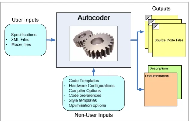
Every autocoder has one or more inputs and generates one or more outputs. These
[image:13.595.168.486.526.729.2]inputs and outputs are summarised in Figure 1.
1.1.1.1. Inputs
Autocoders automatically generate source code using a number of inputs which can be
grouped into two types: User Inputs and &on-User Inputs. Autocoders use these two input types, along with the associated technologies and methods to generate customised
source code for the user’s application.
User inputs are those created by the user and are used by the autocoder to generate the
source code. These inputs are usually created using a separate software tool and
typically take the form of a text file containing the required input data. The input file
describes the design of the software, or the collection of parameters and settings for the
design. Common input file formats include XML files and proprietary file formats
specific to a particular tool.
on-user inputs are inputs that are used solely by the autocoder for the autocoding
process. Most non-user inputs are dependent on the autocoder and the methods used,
however, the majority of autocoders use some form of code templates. As the name
suggests, code templates are plain text files that contain a template of the code to be
generated. Each template is dedicated to one particular part of the output, and typically
contains two content types: Static Content, which does not change throughout the
autocoding process; and Dynamic Content, which is customised based on the user
inputs.
1.1.1.2. Outputs
All autocoders generate one or more source code files. The source code is generated in a
user input files described previously. Some autocoders also allow the user to customise
aspects of the code using a variety of options and settings (separate from the user input
files). This additional customisation may take the form of: code formatting; identifier
naming; code optimisation; programming language; target (processor).
How the source code generated is used by the developer, and what functionality the
source code provides is again dependant on the autocoder used. Autocoders which use
model-based design (MBD) inputs either generate: the application layer of the software
application (such as control algorithms); the structural software components of a
software application, such as those designed using the Unified Modelling Language
(UML) [8]. The code templates for these autocoders represent the fundamental building
blocks of the model, such as loops, conditionals, and classes. These tools could be
referred to as Generic or Application Layer Autocoders.
Other autocoders focus primarily on the layers below that of the application layer
(although it is possible for them to generate configurable application layers, i.e. which
cannot be redesigned). These tools generate code libraries that are customised using the
user’s inputs and later integrated into the user’s application code (created manually or
using an Application Layer Autocoder). The code templates for these autocoders are
less generic, and are larger in granularity; commonly representing an entire source code
file. These tools could be referred to as Specialised or Library Autocoders.
In addition to generating source code, autocoders may also generate other files that are
related to the inputs and the source code generated. The most common additional output
design and implementation i.e. when the design or configuration changes; so too does
the documentation.
1.1.1.3. Operation
The fundamental function of an autocoder is to use the various inputs to generate the
source code. The exact methods and techniques used to achieve this are dependent on
the autocoder in question and the inputs used. However, due to the unformatted textual
nature of source code all autocoders primarily implement a range of string and text
manipulation functions. Depending on the outputs required, the dynamic code sections
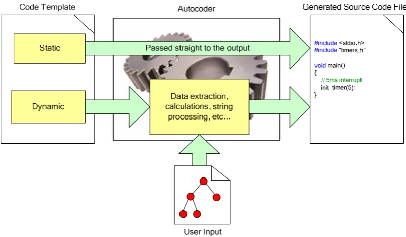
may also perform calculations to determine the source code needed. Figure 2 shows a
simple representation of how an autocoder uses the static and dynamic code templates
[image:16.595.120.522.434.669.2]to generate an output source code file.
Figure 2 - Use of static and dynamic template types to generate source code
The static contents of the code templates; because they are not dependant on the user
formatting and manipulation). For the dynamic contents, the autocoder uses the user
input file(s) to customise the output source code before it is output to the file. This
usually involves calculations contained within the code templates themselves that
calculate or create the code required.
1.1.2.
NetGen
Rapicore, the sponsor of this project, is a specialist solutions provider for supporting the
rapid prototyping of control systems and use techniques such as automatic code
generation, hardware-in-the-loop simulation and safety engineering to provide solutions
for their customers. Rapicore’s main specialisation is in the area of embedded
communication applications that use Controller Area Network (CAN), Local
Interconnect Network (LIN), and FlexRay protocols [9]. Rapicore’s main product, and
the tool of focus for this research, is &etGen; an embedded network design and autocoding tool that allows distributed embedded system developers to design their
networks and then automatically generate source code or related files for their network
implementations.
NetGen is primarily aimed at the automotive industry, supporting the design and
development of the three most common In-Vehicle Networking (IVN) protocols: CAN,
LIN, and FlexRay. Commonly, one or more of these protocols are used within the
vehicle; forming complex networks to support passenger entertainment, comfort, and
safety. As the number of networked electronically controlled functions continues to
increase, development tools such as NetGen can be used to ease the development
process, reduce the product’s time-to-market, and improve the overall robustness and
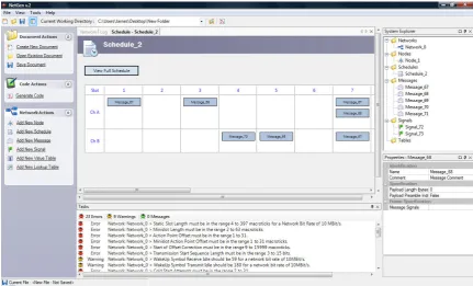
Through NetGen’s Graphical User Interface (GUI) shown in Figure 3, developers can
configure their network and its constituent nodes, messages, schedules, and signals.
Once the user has designed and configured their network, they can then use NetGen to
automatically generate the source code for their application. NetGen could be
considered a Library Autocoder and, unlike MBD and other autocoding tools, generates
source code whose design and requirements are specified by the customer. The code
templates are developed by Rapicore and combined with NetGen so that the customer
[image:18.595.122.554.305.566.2]can configure their network parameters and then generate their customised source code.
Figure 3 - NetGen Graphical User Interface
The source code typically generated by NetGen takes the form of communications
stacks or device configuration header files. Rapicore also provides off-the-shelf
signal-based Application Programmer Interface (API) stacks for each of the network protocols
supported. These ‘libraries’ allow the user’s application layer to communicate on an
embedded network using only signals; abstracting away the underlying communication
etGen’s Autocoding Method
NetGen currently uses XSLT to generate the source code from the embedded network
design. XSLT is an XML-based language which is used to transform XML documents
into other XML and human-readable documents, and was originally developed by the
World Wide Web Consortium (W3C) for use on the internet [10].
Referring to Figure 4, the XSLT processor takes two types of inputs: XML input files
and XSLT stylesheets. The stylesheets contain a collection of template rules,
instructions, and other directives to guide the XSLT processor in the production of the
result document [11].
<xsl value-of> Title $name Date $curdat </xsl value-of>
XML Input
XSLT Code
XSLT Processor Result Document
Figure 4 - XSLT document generation method
NetGen uses this same method to generate source code. The XML input is a System
Description File (SDF); a proprietary file format which contains the network design
data entered through the NetGen GUI. The XSLT stylesheets are the code templates,
with there being one stylesheet for each source code file to be generated. This method
provided a conceptually straightforward, ready to use autocoding method that was
1.2. Research Aim and Methodology
1.2.1.
Research Aim
The XSLT-based code generation method used by NetGen has been used successfully
in a number of past projects. However, it was known that the method had a number of
restrictive issues and limitations. These issues and limitations affected the output
capabilities and the flexibility of the autocoding system, for example, the generated
code was difficult to format consistently and the ability to tailor the code for a particular
processor was not possible.
With autocoding being one of NetGen’s core features it was vital that their autocoding
methods and techniques were able to satisfy their customer’s application requirements;
most of which are provided directly by the customer. The autocoding method and
associated infrastructure must be able to meet these requirements; not only to generate
revenue through NetGen sales, but to also maintain Rapicore’s reputation for delivering
capable solutions.
The aim of the project was to prototype a new autocoding platform which utilised a
more suitable autocoding method. To achieve this aim, the project had 3 objectives:
1. To research the requirements of autocoding tools in the context of Rapicore’s
core business, i.e. embedded network design and development, and the
capabilities that such tools must provide its users;
2. To formally identify the issues and limitations of the current autocoding method
3. To design, implement, and test a solution, and to validate that, both
commercially and academically the autocoding tool and method have
successfully met the stakeholders’ requirements.
It is important to note that Rapicore’s need for an alternative autocoding platform and
method is to provide and improve upon the business’s current autocoding capabilities.
The new tool was not intended to be sold as a stand-alone product and to therefore
directly improve upon the business’s sales figures. This means that an increase in sales
figures or revenue would not be used as a performance or success indicator for this
project. However, in order to future proof the tool, and to not rule out the possible
standalone retail of the tool once it has been made suitable for retail (see Future Work),
the associated requirements have been considered at each stage of the prototype’s
research, design and development.
1.2.2.
Research Methodology
The project adopted a logical and systematic research methodology to achieve the
research aim. This methodology is reflected by the submissions in the portfolio and the
information provided in this Innovation Report.
Figure 5 shows a diagram of the research methodology used. The 4 stages of the
Figure 5 - Research Methodology diagram
1) Literature Review
The first stage of the research methodology was to undertake a comprehensive literature
review. In addition to reviewing the literature, the literature review also covered the
tools developed and used by other Original Equipment Manufacturers (OEMs),
suppliers, and sectors, and the autocoding methods employed by these tools. The
literature review aimed to provide knowledge and understanding of the following
topics:
• Software engineering and software development;
• Software development issues that affect software projects;
• Current MBD and autocoding tools, and the features and benefits these provide;
• The technologies and methods used by current autocoding tools;
• Network design tools and the features and autocoding functionality these tools
provide.
2) Issue Identification
Before a suitable solution could be developed, the issues and limitations with the
following:
• The results of the literature review performed in Stage 1;
• Findings through practical experience with NetGen and its XSLT-based
autocoding method.
Two development projects were undertaken that involved developing a network design,
the XSLT code templates, and then generating the code required for the project. During
these projects any issues, disadvantages, and limitations with the current
implementation were recorded. The results of the literature review were also used to
compare NetGen and the current autocoding method against existing tools and methods.
The result was a collection of recommendations that would guide the research and
development throughout the remaining methodology stages.
3) Solution Research and Development
For the third stage of the research methodology the recommendations documented in
Stage 2 were transformed into a set of requirements. These requirements were then used
to research and develop an innovative solution. The area of innovation was initially
recognised as being associated with the methods used to generate the source code. This
involved researching appropriate techniques and methods, and then developing a
prototype autocoding platform to meet the research aim.
4) Solution Evaluation
Once an appropriate solution had been developed, the final stage of the research
methodology was to evaluate the solution to ensure that the issues had been resolved
used criteria based on the original issues identified in Stage 2 of the research
methodology.
1.3. Portfolio and Innovation Report Structure
1.3.1. Portfolio Structure
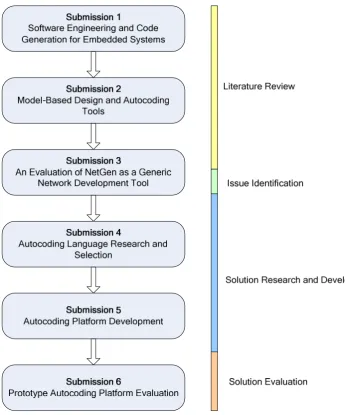
The portfolio consists of 6 submissions numbered 1 through 6. This numbering
corresponds to the intended reading order. These submissions and the research
[image:24.595.132.478.323.739.2]methodology stage under which each submission belongs are shown in Figure 6.
Submissions 1, 2, and the first half of submission 3 contain the project’s literature
review. Submission 1 reviews the wider scope of software engineering and software
development, and discusses the issues experienced by developers and the basic
operation of autocoding tools. Submission 2 reviews several popular MBD and
autocoding tools used for embedded systems; covering their functions, features, and
autocoding methods (where such information was available). The first half of
Submission 3 overviews some competitive embedded network design tools and the
features and autocoding functionality these tools provided.
The identification of the issues and limitations with NetGen’s XSLT-based autocoding
method is contained in the second half of Submission 3. The submission discusses 2
development projects undertaken; covering the aims, implementation, and results of
each project. The submission concludes with a collection of recommendations that
relate to the autocoding method used and the options and features provided to the user.
The research and development of a prototype autocoding platform, which aimed to
solve the issues identified through a new autocoding method, is presented in
Submissions 4 and 5. Submission 4 discusses the research and selection of a more
suitable language for implementing the prototype autocoding platform. The submission
covers the research methodology used to identify the most appropriate language in the
context of this project, the details of the research process, and the results. Submission 5
describes the development of the prototype autocoding platform using the selected
language. The document describes the selection of an appropriate development
methodology and the software’s requirements definition, design, implementation, and
The final submission (Submission 6) presents the evaluation of the prototype
autocoding platform. The document begins by defining and describing the criteria used
for the evaluation. Following this, the document presents a case study that tests out the
autocoding methods implemented by the platform and discusses the results of the
evaluation.
1.3.2. Innovation Report Structure
The structure of this innovation report follows the research methodology and the
associated submissions described above.
Section 2 continues this innovation report by presenting the main findings from the
literature review. Section 3 discusses the issue identification process and the
recommendations made. Section 4 then overviews the research and development of the
prototype autocoding platform. Section 5 overviews the evaluation of the prototype
autocoding platform and the results. Section 6 contains the main discussion, where the
claim of innovation is stated and the innovation is described and justified. The
penultimate section (Section 7) concludes the research project and the final section
2.
Literature Review
NetGen used an XSLT-based method for automatically generating the source code from
the user’s network design, as described in Section 1.1.2. Although this method had been
used successfully in a number of past projects, it was known to Rapicore that this
method had a number of issues and limitations. These issues and limitations had not
been identified, quantified, or documented at the time, and the functions and features
expected by a user from such an autocoding application had not been fully researched
and subsequently implemented.
The literature review focused on the autocoding tools and methods currently used by
others. Based on the knowledge available at the time, the literature review had 3
primary aims:
1. To understand the current state of autocoding research and development;
2. To understand the current functions and features provided by autocoding tools;
3. To understand the current methods and techniques used for the autocoding
process.
The literature review was divided into two stages. The first stage of the literature review
was to develop an understanding of software engineering, software development, and
other associated topics. This provided the basic knowledge required for the main
literature review that followed. The literature review for the first stage covered the
following topics, all of which are presented in Submission 1 of the portfolio [12]:
software engineering; software development models; CASE tools; code generation;
Once a basic knowledge was acquired, the second stage of the literature review focussed
on the options provided by current autocoding and network design tools, and the current
methods used for the autocoding process.
This section will discuss the second stage of the literature review and its findings.
Section 2.1 will discuss the autocoding options provided by the MBD and network
design tools reviewed. Section 2.2 presents the findings from the autocoding method
research. Finally, Section 2.3 will summarise all of the autocoding option and method
findings that were used later in the project.
2.1. Autocoding Options
From previous personal experience with NetGen and the XSLT-based autocoding
method, it was known that the tool provided few options that allowed the user to
customise the source code generated from their network design. This, in most cases,
would result in generated source code that did not entirely suit their application and its
requirements, for example, the code could not be customised to suit a particular
processor or networking hardware.
One part of the literature review, therefore, was to investigate the options provided by
other autocoding tools available. The findings from the literature review could then be
used in the design and implementation of the solution to ensure that these options were
The investigation of autocoding options covered two categories of tools: MBD tools and
Network design tools. The reasons for reviewing these tools, summaries of the tools
reviewed, and the resulting findings are contained within this subsection.
2.1.1.
Model-Based Design and Autocoding Tool Review
MBD is a mathematical and visual method of developing complex control systems.
MBD tools allow developers to graphically construct their models using various
libraries of visual blocks, which can be connected together as required. The developer
can provide stimulus to the model and simulate their designs; observing the system as it
is simulated to ensure that the design functions correctly [13].
MBD tools were reviewed during the literature review due to their common integration
with autocoding tools. In this context, the autocoders are used to automatically generate
the source code from the user’s model. The MBD tool review covered 3 tools: Simulink
[14] (The MathWorks), SCADE [15] (Esterel Technologies), and ASCET-MD [16]
(ETAS). These tools were chosen in particular due to their: use for developing
embedded systems, like NetGen; their popularity and widespread use throughout
industry.
Autocoder Company Model-based
Design tool
Description
Real-Time Workshop [18] The MathWorks Simulink Generates ANSI C source code
Stateflow Coder [19] The MathWorks Stateflow Generates ANSI C source code from a
Stateflow diagram
TargetLink [20] dSPACE Simulink Generates ANSI C
SCADE Code Generators [21][22][23]
Esterel Technologies
SCADE Suite Consists of 3 separate autocoders for 3
standards: DO-178B, IEC 61508, EN50128
ASCET-SE [24] ETAS ASCET-MD Generates C source code from
ASCET-MD model
The literature review covered 5 autocoders, which were chosen due to their specific
integration with the MBD tools also reviewed. The autocoding tools reviewed are
summarised in Table 1. The full review of the MBD and associated autocoding tools
can be found in Submission 2 [17].
The literature review for the MBD and associated autocoding tools used product
datasheets and the tools’ websites, as well as a number of papers where developers had
used these tools in their applications. In addition, due to the availability of Simulink and
TargetLink, an example autocoding model was created to gain practical experience of a
3rd party tool.
2.1.2.
Network Design and Autocoding Tool Review
Embedded network design tools can be used by developers to define and specify the
network parameters of their application. Some tools also allow the developer to simulate
and test their network designs without having the hardware present.
Embedded network design and autocoding tools were reviewed to match the intended
market of NetGen. The network design review covered 9 tools in total; some of which
were network design tools only; some were autocoders only; and some provided both
network design and autocoding functionality. The tools reviewed are summarised in
Table 2. The particular network design tools reviewed were selected due to their focus
on embedded networking protocols such as CAN, LIN, and FlexRay. These matched the
As with the model-based design and autocoding tool review, the literature for the
review came from the tools’ datasheets and websites. The full network design and
autocoding tool review can be found in the first half of Submission 3 [29].
Tool Developer Description
Design and Analysis
Volcano Network Architect Mentor Graphics
[25]
CAN and LIN
DaVinci Vector [26] System, network, and data design
CANoe Vector Development, testing, and analysis of ECUs
and networks with simulation and emulation of ECUs
Tresos Designer Elektrobit [27] System design and configuration
TTX-Plan TTTech [28] Network design and automatic scheduling tool
for distributed automotive systems based on FlexRay.
LIN-Plan TTAutomotive Design and development of LIN networks.
Code Generation
Volcano Target Package Mentor Graphics Precompiled object libraries and associated
documentation
DaVinci Vector
Tresos Studio & AutoCore Elektrobit AUTOSAR module configuration and module
generation
TTX-Build TTAutomotive Modular configuration tool for AUTOSAR
components.
Table 2 - Embedded network design and autocoding tools reviewed
2.1.3.
Findings
The literature review included 15 MBD, network design, and autocoding tools from 9
companies. The review covered the autocoding functions and features provided by these
tools, such as: optimisations, code customisation, language support, processor and
compiler support, documentation generation, and standard support. A summary of the
review’s main findings is provided below.
Optimisations
ASCET-MD, SCADE, Simulink and TargetLink allow the user to select their desired
trade-off between various properties of the code and its implementation such as: code
size; processing speed; and RAM (data) size. ASCET-MD, Simulink and TargetLink
provide the greatest level of optimisation as they can tailor the code for specific
processors, allowing the generated code to take advantage of the specific hardware
resources available.
Code Customisation
SCADE, Simulink and TargetLink allow the user to customise the non-functional form
of the source code generated. This customisation covers code formatting (indentation,
vertical spacing, and whitespace) to improve the visible structure and readability of the
code. Users can also customise the identifier naming styles used for items such as
variables and functions, for example, the use of Camel Case (e.g. MyVariable) or Pascal
Case (e.g. myVariable) for identifiers. Of the tools reviewed, TargetLink provided the
greatest level of code customisation, enabling the user to generate source code that
better met a developer’s or organisation’s coding standard.
Code Language Support
All of the MBD autocoders shown in Table 1 were able to generate source code in
ANSI C; mainly due to the popularity of this language in embedded applications.
SCADE also allowed users to generate source code in other languages including
Qualifiable C, Ada, and Spark Ada. Ada in particular is a common language for
Processor and Compiler support
VTP, Tresos, DaVinci, ASCET-SE, Simulink, and TargetLink provide code generation
and optimisation for specific embedded processors. This functionality is often provided
through separate modules that are sold separately from the main MBD or autocoding
tool. In addition to this, it was found that the autocoders for the network design tools
generated pre-compiled code (in contrast to NetGen which generates non-compiled
source code). This is due to the philosophy of AUTOSAR (see AUTOSAR Support
below) and the need for automotive developers to protect their intellectual property in
such a development environment.
Code documentation generation
All of the tools reviewed provide automated documentation features that document the
generated code and link this code to the input model. The documentation provides
information such as the code generation options and the optimisations that were used to
generate the code. This enables developers to repeat previously used model and code
generation configurations for the same or other similar models.
Coding standard support
ASCET-MD and SCADE can generate source code that adheres to a variety of coding
standards or guidelines. These standards and guidelines include: DO-178B, IEC 61508,
EN50128, and MISRA C. MISRA C is particularly popular in the automotive industry
and DO-178B is used in the aerospace industry. Tools which support the safety-related
standards such as DO-178B (e.g. SCADE) are often expensive due to the autocoder’s
AUTOSAR Support
It was clear from the network design tools covered that the Automotive Open Systems
Architecture (AUTOSAR) standard has a strong influence on the tool itself and the intended purpose of the autocoder.
AUTOSAR is a recent automotive software standard developed by a number of
industrial partners including BMW, Ford, Toyota, and Volkswagen. The main aims of
AUTOSAR are to: standardise automotive software; provide the scalability of software
to different vehicle platforms and variants; increase the use of off-the-shelf software
components in vehicles. The standard specifies a number of different software layers
and components with well defined interfaces so that they can be easily bought in by the
development team and connected together without modification [30].
Network design and autocoding tools are of great benefit to developers where
AUTOSAR is concerned as the standard is large and complex. There are a large number
of individual software modules present in the standard with each having well defined
interfaces, interactions, and configurations. Due to AUTOSAR’s standardisation it is
important that all of the modules match the AUTOSAR requirements, and with a design
tool tailored as such this standard conformance can be better guaranteed.
2.2. Autocoding Methods
There are various methods and techniques for automatically generating source code;
however, most of these methods are based on the same basic principles as described in
the introduction. In order to develop a suitable and innovative solution an awareness of
method literature review, therefore, was to investigate the autocoding methods currently
being researched and used to aid the research and development of a solution later in this
project.
The literature review so far has focused on tools aimed at embedded systems. These
were chosen to match the intended end-user of Rapicore’s NetGen tool. The autocoding
method review investigated the wider field of autocoding, in addition to those methods
used by the MBD and network design tools reviewed. This was necessary in order to
increase the scope of literature and methods available, for example, with the exception
of the method used by The MathWorks, most of the tools reviewed did not disclose this
information.
During the literature review, two main areas where identified as being the focus of
current autocoding method research. The first area covered autocoding methods that
related to the generation of code for compilers. These methods focus on the more
mathematical aspects of software and low-level optimisations which are beyond the
scope of this research project. The second area covered autocoding methods that
focused on the high-level, template-oriented autocoding methods. The second area was
the focus for this part of the literature review.
This subsection will present the findings from the autocoding method literature review
performed. Specifically, the subsection will cover: code template implementation
(2.2.1); autocoder front-ends (2.2.2); processing (2.2.3). Note that some of the findings
was performed, some additional research was seen as necessary for the purposes of this
research project.
2.2.1.
Code Template Implementations
The code templates, as mentioned in the introduction, contain a template of the code to
be generated. These code templates are used together with the input files to generate the
required source code.
Source code templates are typically written in a particular scripting language. These
script-based templates extract the required data from the input data source, apply it as
necessary to the template and then output the result.
One specific method found during the literature review allowed template developers to
combine dynamic scripts with the static contents of any ASCII formatted text file. This
method was implemented by a tool called CodeSmith Studio, which accepts templates
written in a language similar to ASP.NET and may contain scripting code in C#,
VB.NET, or JScript [30]. A brief example of a CodeSmith Studio template is shown
below.
<%@ CodeTemplate Language="C#" TargetLanguage="HTML" %> ...
<html> <head>
<title>Test Report</title> </head>
<body>
<h1><%= TestReport.ProjectName %></h1>
<h2>Test Date: <%= TestReport.TestDate %></h2> </body>
</html>
in C#, VB.NET, or JScript. The dynamic scripts contained within these tags are first
parsed by the CodeSmith processor. The processor then replaces the original tag with
the result of the evaluated script.
CodeSmith Studio also provides a GUI front-end which aids the user in developing the
templates required for their applications. This will be discussed further in the following
subsection.
2.2.2.
Autocoder Front-Ends
Most of the autocoding tools researched during the literature review provided the user
with a front-end. The intended purposes of these front-ends include:
• The collection of input data from the user (rather than having an input file);
• Allowing the user to configure the autocoding process;
• Aiding the developer during the template development process.
An example of a front-end which is used for capturing the user’s input data is a tool
intended for transforming Software Design Patterns into source code implementations
[32]. This tool consisted of a Web Browser front-end (Figure 7) for capturing the user’s
inputs and responding to user events (such as the clicking of a button).
Once the required information has been captured, the Web Browser then invokes a
Perl-based mapper that maps the user’s data and selections to the appropriate code templates
for the required design pattern. The mapper then passes that information to a custom
processor called COGE&T (COde GENeration Template), which then generates the
source code for the design pattern selected. This process and the flow of control is
[image:38.595.139.515.491.742.2]shown in Figure 8.
Figure 8 – Implementation of the design pattern tool [32]
In terms of front-ends for aiding the template development process, there was
CodeSmith Studio who’s template implementation was discussed in Section 2.2.1.
The CodeSmith Studio front-end (Figure 9) provides features that are similar to those
provided by Microsoft’s Visual Studio [33]; the most obvious being that of IntelliSense.
IntelliSense monitors the text written by the user in real-time and provides a list of
available functions and data that can be used in the current context.
In addition to IntelliSense, CodeSmith also provides syntax highlighting, project
navigation, and syntax checking to further increase the productivity of the developer.
2.2.3.
Processing
All autocoders reviewed are based around one or a number of existing scripting
languages. The use of existing scripting languages allows companies to develop
autocoding tools using existing interpreters, which have already been thoroughly tried
and tested by other developers. In addition, the use of scripting languages themselves,
as opposed to compiled alternatives, provides an easier to use and compatible
processing method for ASCII text files such as source code templates.
Autocoders that implement existing scripting languages use the script processor for the
language in question. For example, Java-based autocoders use the Java Runtime
Environment (JRE) to process the Java code templates. Similarly, XSLT-based
autocoders (such as NetGen’s method) use the XSLT processor to process the
XSLT-based code templates.
In terms of the processing performed in the code templates, it was found that there was
a mixture in the mathematical and computational complexity involved. Some tools used
as the Design Pattern tool discussed previously, and demonstrated in Figure 7. In this
instance, the code templates contain a mark-up which is later replaced by the data.Other
tools provide, or could potentially provide, a large amount of dynamic computations, an
example of which being the code templates that can be developed using CodeSmith
Studio.
It was noted that some tools customise or borrow principles (such as syntax) from an
existing scripting language, e.g. CodeSmith Studio, whose syntax is very similar to that
of ASP.NET. Unfortunately, many high-value tools such as the MBD and autocoding
tools reviewed do not disclose the methods used unless such knowledge is required by
the user to customise the autocoding output.
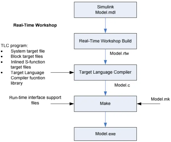
Real-Time Workshop and TargetLink are examples of tools that provide information on
how the high-level processor works (however, the underlying operation is not
disclosed). These products used a propriety tool called the Target Language Compiler,
or TLC. The TLC is part of the Mathwork’s Real-Time Workshop code generator and
transforms a specially compiled Simulink block diagram into ANSI C source code.
The TLC is an integral part of Real-Time Workshop, enabling the user to customise the
C code generated from any Simulink model. Through customisation, users can produce
platform-specific code, or they can incorporate their own algorithmic changes for
performance, code size, or compatibility with existing methods. An overview of the
After reading in the model.rtw file, the TLC generates its code based on; target files,
which specify particular code for each block; model-wide files, which specify the
overall code style. The TLC works like a text processor, using target files and the
model.rtw file to generate ANSI C code. To create a target-specific application,
Real-Time Workshop also requires a template makefile that specifies the appropriate C
compiler and compiler options for the build process.
Figure 10 - Overview of the TLC process
The TLC uses a mark-up syntax similar to that of the HyperText Markup Language
(HTML) and XML, along with the power and flexibility of Perl and other scripting
languages, and the data handling functionality of MATLAB to go from the model file to
source code. Through practical use it was found that TargetLink also used TLC, but
[image:41.595.164.459.264.508.2]2.3. Summary
The main part of the literature review focused on the autocoding tools and methods
currently used by others. The literature review had 3 primary aims:
1. To understand the current state of autocoding research and development;
2. To understand the current functions and features provided by autocoding tools;
3. To understand the current methods and techniques used for the autocoding
process.
The observations made during the literature review are summarised in the following
subsections. These findings were later considered during the NetGen analysis (Section
3) and the prototype autocoding platform’s development (Section 5) to ensure that a
suitable and effective solution was created.
2.3.1. Model-Based Design and Autocoding Tools
Table 3 shows a summarised comparison of the MBD and autocoding tools reviewed
(see Appendix A for the full comparison table).
ASCET-MD SCADE Simulink TargetLink
Code Optimisation Yes Yes Yes Yes
Embedded Support Yes No Yes (with
Embedded Coder)
Yes
Specific Processor Support
Yes No Yes (with
Embedded Target)
Yes
Code Customisation Unknown Yes Yes Yes
Standards/Guidelines MISRA-C IEC 61508
SIL3
D0-178B IEC 61508
EN 50128 MISRA-C
None None
Code Languages ANSI C Ada & Ada
Spark C and Qualifiable C
ANSI C (Standard), Any other language
using S-Functions
ANSI C (Standard),
Any other language using
S-Functions
Autocoding tools allow the user to select their desired level of code optimisation. This,
for example, enables the developer to trade-off code size for processing speed and vice
versa. Tools that also provide specific target support such as Simulink and TargetLink
are able to provide further levels of optimisation; tailoring the code to make more
effective use of the hardware resources available. It is worth noting that although
SCADE is the only MBD tool that does not provide this processor specific, the reason
for not providing such support is due to the tool’s certification requirements for
standards such as DO-178B.
SCADE, Simulink and TargetLink allow the developer to customise the formatting and
style of the generated source code (ASCET-MD may have provided this, but this could
not be confirmed). Code formatting includes: whitespace, horizontal spacing, and new
lines. Style refers to the naming styles used for identifier names such as variables and
functions. Such customisation enables developers to generate code that is easier to read
and better meets a company’s coding standards; helping minimise the need for manual
code modification post-generation.
All four of the MBD and autocoding tools can generate source code in ANSI C.
SCADE, Simulink and TargetLink also allow the user to generate source code in other
languages such as Ada. This functionality widens the tools market; allowing developers
to generate source code that matches their development and application requirements.
ASCET-MD and SCADE support a number of coding standards and guidelines such as
can help ensure that the code generated is more robust and reliable for use in the
intended, often safety-critical applications.
2.3.2. Network Design Tools
The network design tool review found that, as well as providing design entry and
validation, the tools also allowed developers to export their designs as one or more
network description files such as FIBEX (Field Bus Exchange) and LDF (LIN
Description File). These files contain the configuration of the nodes, messages, signals,
and schedules within the network, and allow developers to easily communicate and
transport their designs between other tools and parties involved in the system’s
development.
The three most common network protocols supported by current design tools are: LIN,
used primarily for automotive body control; CAN, the most widely implemented
protocol of the three, which is used for a range of functions in many industries; and
FlexRay, a high-speed fault tolerant protocol. Although these can be used in a number
of applications from aerospace to automation, they are primarily used in automotive
control systems.
With all of the tools reviewed being focused on in-vehicle network development, they
all provided support for the AUTOSAR standard. The tools allow developers to
configure and automatically generate AUTOSAR software that can be used in their
applications.
pre-compiled object libraries, rather than source code. This links in with the AUTOSAR
functionality (and the protection of Intellectual Property (IP)), and therefore makes code
customisation (in terms of formatting and styling) irrelevant for these tools.
2.3.3. Autocoding Methods
The autocoding methods research investigated code template implementations,
autocoding front-ends, and code processing. The review included both experimental and
commercial tools such as CodeSmith Studio, COGENT, and TLC.
The research found that tools such as CodeSmith Studio and COGENT in particular can
effectively use GUIs; not only start the autocoding process, but to: collect additional
information from the user; aid the development of the code templates.
All of the autocoding tools researched are based on scripting languages; commonly
using existing scripting languages to a greater or lesser extent. Those tools that use
existing scripting languages to a lesser extent often add additional functionality to
existing languages or borrow concepts from a particular language.
One of the main elements of the autocoding methods used is the addition of custom
mark-up to the code templates. These mark-ups are either used for simple text
replacement, i.e. the replacement of the mark-up with the value required, or they were
found to contain scripts so that computations could be performed within the template.
XML, and XSLT for various aspects and functions within the tool. The combination of
multiple languages allows the autocoder to benefit from the key functions and features
provided by a variety of languages and technologies, e.g. XML for data storage and
representation, and Perl for processing.
CodeSmith Studio and TLC allow the users to develop their own code templates or
customise existing code templates to suit their application. This ability means that such
tools can be customised to meet the developer’s requirements, allowing them to add
3.
NetGen Analysis
The literature review discussed in the previous section resulted in a list of options
offered by current autocoding and network design tools. These covered items such as
code optimisations, language and processor support, and code documentation
generation. The literature review also investigated the methods and techniques currently
used for the autocoding process, and covered template implementations, front-ends, and
processing.
With the functions and features available in other autocoding tools now known, the next
stage of the project involved the analysis of NetGen and the XSLT-based autocoding
method to identify the issues and limitations. The aim of this analysis was to provide a
list of recommendations based on the issues and missing options identified. These
recommendations would then be used to define the requirements of a more suitable and
capable autocoding method.
It was decided that the most effective way of identifying the issues and missing features
was through practical experience with NetGen and the XSLT autocoding method.
Therefore, two practical projects were undertaken which involved adding autocoding
support for the CAN and FlexRay embedded network protocols. These projects were
representative of a typical autocoding development; providing the same functionality
and adhering to the same or similar requirements and design of previous projects
undertaken before starting this project. This section will discuss the aims and results of
these two projects (Sections 3.1 & 3.2), and then present the autocoding method and
projects undertaken and corresponding discussion can be found in portfolio Submission
3 [29].
3.1. CAN Project
3.1.1.
Aims
Prior to the CAN project, NetGen supported the configuration of CAN networks but did
not provide CAN autocoding functionality. The aim of the CAN project was to add this
support to NetGen. The code to be generated from NetGen had a number of
requirements defined by the company and typical customer requirements. These
requirements were:
• To provide a signal-based interface for the user’s application;
• To abstract the low-level CAN implementation away from the user;
• To support three bit formats for the packing and unpacking of signals within
CAN messages (Motorola Forward, Motorola Backward, Intel);
• To generate code specifically for the NXP (formally Philips) ARM7 LPC2129
32-bit Microcontroller [34].
3.1.2.
Results
One of the main problems found during the CAN project was with the generation of
code using XSLT. As mentioned in the introduction, XSLT was developed by the W3C,
and was intended for transforming XML documents into other XML and
human-readable documents. The main problems found when using such a technique for
![Figure 8 – Implementation of the design pattern tool [32]](https://thumb-us.123doks.com/thumbv2/123dok_us/9728843.473814/38.595.139.515.491.742/figure-implementation-design-pattern-tool.webp)