Original citation:
Wang, F., Ma, Z., Gao, W., Zhao, X., Tian, Yanling, Zhang, D. and Liang, C.. (2014) Dynamic modeling and control of a novel XY positioning stage for semiconductor packaging. Transactions of the Institute of Measurement and Control, 37 (2). pp. 177-189.
Permanent WRAP url:
http://wrap.warwick.ac.uk/76445
Copyright and reuse:
The Warwick Research Archive Portal (WRAP) makes this work of researchers of the University of Warwick available open access under the following conditions. Copyright © and all moral rights to the version of the paper presented here belong to the individual author(s) and/or other copyright owners. To the extent reasonable and practicable the material made available in WRAP has been checked for eligibility before being made available.
Copies of full items can be used for personal research or study, educational, or not-for-profit purposes without prior permission or charge. Provided that the authors, title and full bibliographic details are credited, a hyperlink and/or URL is given for the original metadata page and the content is not changed in any way.
Publisher statement:
http://dx.doi.org/10.1177/0142331214541598
A note on versions:
The version presented here may differ from the published version or, version of record, if you wish to cite this item you are advised to consult the publisher’s version. Please see the ‘permanent WRAP url’ above for details on accessing the published version and note that access may require a subscription.
For Peer Review
Dynamic modeling and control of a novel XY positioning
stage for semiconductor packaging
Wang Fujun1, 2, Ma Zhipeng1, Gao Weiguo1*, Zhao Xingyu1, Tian Yanling1, Zhang Dawei1, and Liang Cunman1
1 Tianjin Key Laboratory of Equipment Design and Manufacturing Technology, School of Mechanical Engineering, Tianjin University, Tianjin 300072, China
2 Department of Mechanical Science and Engineering, University of Illinois at Urbana-Champaign, Urbana, IL 61801, USA
Abstract: This paper presents the dynamic modeling and controller design of an XY
positioning stage for semiconductor packaging. The XY stage is directly driven by two
linear voice coil motors (LVCMs), and motion decoupling between the X- and Y- axes is
realized through a novel flexible decoupling mechanism based on flexure hinges and
preloaded spring. Through bond graph method, the dynamic models of X- and Y-axes
servomechanisms are established, respectively and the state space equations are derived.
A control methodology is proposed based on force compensations and the performance
of the XY stage is investigated by simulations and experimental tests. The results show
that the XY stage has good performance. When the reference displacements are defined
as 2 mm, the settling time of the X-axis movement is 64 ms, and the overshoot is 0.7%.
Y-axis settling time is 62 ms, and the overshoot is 0.8%. X-axis positioning accuracy is
1.85 µm and the repeatability is 0.95 µm. Y-axis positioning accuracy and repeatability
are 1.75 µm and 0.9 µm, respectively. In addition, the stage can track linear, circular and
complex trajectories very well.
Keywords:XY positioning stage, Dynamic modeling, Control
*
Corresponding author: Tianjin Key Laboratory of Equipment Design and Manufacturing Technology,
For Peer Review
School of Mechanical Engineering, Tianjin University, 92 Weijin Road, Nankai District, Tianjin 300072,
China. Email: [email protected], Tel./fax: +86 022 87401950
1 Introduction
Recently the trend towards miniaturizing semiconductor products such as
integrated chips and MEMS has stimulated extensive research on semiconductor
packaging (Li and Xu, 2011; Aized and Shirinzadeh, 2011; Liaw and Shirinzadeh, 2008;
Fatikow et al., 2008; Zhang et al., 2013; Wang et al., 2009). As one of the essential
components of semiconductor packaging machines, high speed XY positioning stage
with a micro scale resolution and motion stroke of over several millimeters plays an
important role in the packaging process (Wang et al., 2011; Hwang et al., 2010; Liang et
al., 2010; Wang et al., 2014).
Numerous new drive technologies (e.g., piezoelectric, electrostatic, etc.) have been
utilized in the XY positioning stages (Tian et al., 2009; Li and Xu, 2011). However,
electromagnetic actuation is still considered to be the best choice for the motion with a
long stroke of more than several millimeters (Khan et al., 2011). Most traditional XY
stages equipped with rotational motors and ball screws have disadvantages of reduced
accuracy, complex mechanical structure and low reliability, and it can not meet the
stringent requirements of precision manufacturing and assembly industry (Hace et al.,
2011; Liu et al., 2003). Direct-drive motors have the advantages of low friction and high
mechanical stiffness, and thus they have been increasingly used in the high speed
precision positioning XY stage (Dejima et al., 2005; Sanchez and Ricolfe, 2012).
Consequently, it is very essential to study on the dynamic modeling and controller
For Peer Review
design of the direct-drive stage to cope with the increasingly demanding requirements.
Dynamic model is the basic of dynamic analysis and controller design, so many
researchers have been working on the dynamic modeling and analysis of XY stages. Teo
et al. (2007) and Zhao et al. (2010) established the dynamic models of the mechanical
system of an H-type gantry direct-drive stages using Lagrangian equation. Cai et al.
(2011) carried out the dynamic modeling of a 3-DOF ultra-precision positioning stage
with air bearing through rigid body finite rotation Jourdain Principle and the vibration
frequency and mode were analyzed and discussed. A numerical method based on
mechanical energy conservation was adopted to calculate the undamped natural
frequency of a parallel-kinematic positioning XY stage (Ferreira et al., 2007). Fung et al.
(2009) achieved the dynamic model of a dual-stage XY precision positioning table with
the aid of analytical method and experimental identification approach. The high speed
precision positioning XY stage is a complex system which integrates mechanical,
electrical and other physical processes. During the high speed motion with short strokes,
XY stage usually shows the characteristics of high order, multi variables and
time-varying, so the dynamic behavior of the XY stage becomes extremely complex.
The dynamic model obtained through the above traditional theoretical modeling
methods can not accurately demonstrate the actual dynamic behavior of such complex
systems. As a global dynamic modeling method, bond graph represents the system in
terms of energy and information flow, and the advantage of this method is that the
dynamic model in multi-energy domains can be constructed in a rather small set of ideal
elements (Wang et al., 2009; Sun et al., 2011). As a result, it is very suitable for the
For Peer Review
dynamic modeling and characteristic analysis of high-speed and high-accuracy
positioning XY stage.
The controller is one of the important elements of an XY positioning stage, because
of its ability to eliminate positioning errors. In the literature,
proportion-integration-differentiation (PID) compensator is by far the most widely used
form of feedback controller (Ang et al., 2005). However, it can not meet the
increasingly stringent performance requirements of the high speed XY positioning stage
(Liu, et al. 2005). Ding et al. (2006) presented a combination of friction compensator
and disturbance observer (DOB) to eliminate the uncompensated friction and other
external disturbances for a direct-drive stage. Tomizuka (1987) proposed a zero phase
error tracking controller (ZPETC) based on approximate inversion of the closed-loop
system to eliminate time delay disturbance and improve tracking performance of an XY
stage. Several advanced control theories including the adaptive robust control (ARC)
(Xu and Yao, 2000), variable-structure control (VSC) (Adamy and Flemming, 2004),
iterative learning control (Wu and Ding, 2007), fuzzy control (Mou and Sung, 2012)
and neural networks control (Xu and Li, 2012), were proposed to control direct-drive
positioning stages, and they can provide appropriate level of performance. However,
their applications are limited in industry applications by the expensive algorithms and
calculations. In addition, these studies mostly focused on linear motor direct-drive XY
stages.
In this paper, the dynamic modeling and controller design of a precision
positioning XY stage for semiconductor packaging are presented. Firstly we describe the
For Peer Review
configuration of the XY stage with a novel decoupling mechanism. Then considering the
characteristics of the servomechanism, the dynamic model is established using bond
graph method. On the basis of force compensation principle, the controller is designed.
Finally the performance of the XY stage is evaluated by simulations and experimental
tests.
2 Dynamic modeling of the XY stage
Prior to the modeling of the XY positioning stage, a brief description of the
mechanism of the XY stage will provide a good basis for the subsequent discussion.
2.1 Mechanical structure
The mechanism of the LVCMs direct-drive XY stage is shown in Fig.1. The stage is
mainly composed of X- and Y-axes LVCMs, X- and Y-axes tables, the motion
decoupling mechanism and the base. Linear grating encoders are used as the feedback
sensors for X- and Y-axes tables. The X- and Y-axes motors are both fixed on the base.
X-axis table is connected with X-axis LVCM by the pushing plate. Y-axis table is located
above X-axis table, and it is also connected to the Y-axis LVCM by the motion
decoupling mechanism. The Y-axis motor is connected to the guiding fin which can
move in Y axis on the sliding guides. One end of the preloaded connecting rod is
mounted on the guiding fin and the other end is connected to the preload spring. The
preload spring is also mounted on the guiding fin. The front and back roller bearings are
mounted on the guiding fin and roll contact the front and back lapping plates,
respectively.
The decoupling mechanism is composed of the guiding fin, preloaded connecting
For Peer Review
rod, back roller bearing, front roller bearing, back lapping plate, front lapping plate,
flexure hinges and the preloaded spring. The Y-axis LVCM is connected to the guiding
fin which can move in Y axis on the sliding guides. One end of the preloaded connecting
rod is mounted on the guiding fin and the other end is connected to the preload spring.
The preload spring is also mounted on the guiding fin. The front and back roller
bearings are mounted on the guiding fin and roll contact with the front and back lapping
plates, respectively.
The Y-axis motor generates a force, which will drive the Y-axis table by the
flexible decoupling mechanism. When X-axis motor generates a force, the Y-axis table
will move with X-axis table in X direction, the front and back roller bearings roll along
the front and back lapping plate separately, and thus the motion decoupling of X- and Y-
axes is realized. Thus the motion mass can be greatly reduced. Moreover, the dynamic
load and the residual vibrations during high speed motion and the instant interference
generated when X- and Y-axes motion at the same time can be suppressed by the slight
deformation of flexure hinges.
Fig.1 The configuration of the LVCMs direct-drive XY stage.
For Peer Review
2.2 Dynamic modeling using bond graph method
Fig.2 The dynamic model of the LVCMs direct-drive XY stage: (a) for X-axis, and (b) for Y-axis.
The dynamic model of the VCMs direct-drive XY stage is shown in Fig.2, where U
is the voltage applied to the VCM, Rm is the resistance of the VCM coil, i is the current
intensity through the coil, Lm is the inductance of the VCM coil, Mr is the mass of the
coil, M1 and M2 are the equivalent mass of the Y-axis guiding fin and table, respectively,
M3 is the mass of the X-axis table, K1 and C1 are the connecting stiffness and damping
between coil and the guiding fin, respectively, K is the stiffness of the preload spring, Kt
is the stiffness of the flexure hinge, Kc is the contact stiffness between the bearing and
the lapping plate, C2 is the equivalent damping between the Y-axis guiding fin and table,
FL is the output force of the coil, Fd is the X-axis damping force, Fs is the X-axis
equivalent spring force, Fdy is the Y-axis damping force, Fsy is the Y-axis equivalent
spring force, FF1 is the friction of the X-axis coil, FF2 is the friction of the X-axis table,
FF1y is the friction of the Y-axis coil, FF2y is the friction of the Y-axis table, Fi1 is the 3
For Peer Review
inertia force of the X-axis coil, Fi2 is the inertia force of the X-axis table, Fi1y is the
inertia force of the Y-axis coil, and Fi2y is the inertia force of the Y-axis table.
A VCM is basically an electromagnetic transducer in which a coil is placed in a
magnetic pole gap experiences a force proportional to the current passing through the
coil. Assuming that the force generated by the VCM is independent of the position, the
governing equations can be written as equations (1) and (2)
m m B
di
U = R i + L + K v
dt (1)
F r L
dv
F = K i = M F
dt + (2)
where v is the motion velocity of the VCM coil, F is the force generated by the VCM,
KB is the coefficient of inducted electromotive force, and KF is the force coefficient.
The dynamics of the X- and Y- axes servomechanism is represented by the
following second-order linear differential equations.
2
3 2 1 1 L F2
d x dx
M C K x F F
dt + dt + = − (3)
2 2
y y y y
d y dy
M C K y F
dt + dt + = (4)
where x is the displacement of X-axis table, 1
2 0 0 y M M M = ,
1 2 2
2 2
y
C C C
C C C + − = − ,
1 2 2
2 2
y y
y
y y
K K K
K K K + − = − , 1 2 y y y =
, 2
L y F F F F = −
, 2
2
2 2
t r c
y c
t t c c
K K K
K K
K K K K KK
= +
+ + ,
y1 and y2 are the displacements of Y-axis guiding fin and table, respectively.
Exponential friction model is adopted, and it can be expressed as
( )
( )
(
)
2 ) ( f s v vF f f c st c f
F v signum v F F F e v
−
= ⋅ + − ⋅ +µ (5)
where vf is velocity, Fc is coulomb friction, Fst is static friction, vs is Stribeck velocity,
For Peer Review
and µ is viscous friction coefficient.
Bond graph is an explicit graphical tool for capturing the common energy structure
of systems, and by this approach, a physical system can be represented by symbols and
lines, identifying the power flow paths. The basic variables in bond graph are effort (e),
flow (f), time integral of effort (p(t)) and the time integral of flow (q(t)). Based on the
principle of bond graph method, the output force of VCM is defined as the effort source
(Se), the connecting damping and friction are defined as resistor elements (R), and the
connecting stiffness is defined as capacitor element (C). Thus the bond graph for X- and Y- axes servomechanism can be obtained, and they are described in Fig.3(a) and
Fig.3(b), respectively.
In Y-axis bond graph, according to the 1-junction that connects the bonds of 8,
9 and 10, the following equation can be gotten.
9 1 C1 10
L
F =K q + v (6)
Considering the 0-junction that connects the bonds of 7, 8 and 11, the
following equation can be obtained.
1
10 r 1 r
dy
v v v v
dt
= − = − (7)
Considering the 0-junction that connects the bonds of 13, 14 and 17, the
following equation can be gotten.
1 2
16 1 2
dy dy
v v v
dt dt
= − = − (8)
Considering the 1-junction that connects the bonds of 11, 12 and 13 and the
1-junction that connects the bonds of 17, 18 and 19, the following equation can be
For Peer Review
achieved.
( )
12 18
1 2 19 19
L
F =M a +M a + f v +µv (9)
And
( )
2 19
19 = ( 19)( ( ) )
s
v v
c st c
f v signum v F F F e
−
+ − (10)
According to the 1-junction that connects the bonds of 14, 15 and 16, the
following equation can be gotten.
1 12 eq 15 2 16 L
F −M a =K q +C v (11)
where 2
2
t c
eq c
t c
K KK
K K
K K K
= +
+ +
Fig.3 The bond graph of the LVCMs direct-drive XY stage: (a) for X-axis, and (b) for Y-axis.
For Peer Review
Considering the inertia and capacitance effects have great significances to the
dynamic performance of the system, the generalized momentum p(t) of inertia element
and generalized displacement q(t) are selected as the state variables of the XY stage.
X-axis state variables can be expressed as
[
2 6 9 12]
2 69 12 3 1 T T m x r e
p p q p f L f M f M
K
=
=
x (12)
The input variable ux =
[ ]
e1 , and the output variable is yx =[ ]
f12 . According tothe relation of the power flow and the definition of basic elements, the X-axis state
space equation and output equation can be gotten, and they are written as
x = x x+ x x
&
x A x B u (13)
x = x x+ x x
y C x D u (14)
where 1 1 x 3 1 1 3 0 0 0 1 1 0 0 0 0 m B m r B m r r r R K L M K C K L M M M C C M M − − − − = − − + µ A , 1 0 0 0 = x B , 3 1
0 0 0 0 0
M
=
x
C ,and Dx =0.
Y-axis state variables can be expressed as
[
]
9 152 6 9 12 15 18 2 6 12 1 18 2
1
T T
y m r
eq
e e
p p q p q p f L f M f M f M
K K = = x (15)
The input variable uy =
[ ]
e1 , and the output variable is yy =[ ]
f12 . The relationbetween the effort and flow variables of resistor elements in the Y-axis bond graph can
For Peer Review
be described by
[
3 10 16 19 20] [
3 10 1 16 2 ( 12) 20]
T T
m
e e e e e f R f C f C f f f
= = µ
e
(16)
Based on the integral causal relations of the basic elements in the Y-axis bond
graph, the following equation can be obtained.
[
2 6 9 12 15 18] [
2 6 9 12 15 18]
T T
y = p p q p q p = e e f e f e
& & & & & & &
x (17)
According to the relation of the power flow and the definition of basic elements,
the Y-axis state space equation and output equation can be achieved, and they are
written as
y = y y+ y y
&
x A x B u (18)
y = y y+ y y
y C x D u (19)
where
1 1
1
1
1
1 1 2 2
1
1 2
1 2
2 2
1 1
0 0 0 0
0 0
1 1
0 0 0 0
0
1 1
0 0 0 0
0 0 0
m B m r B m r r eq r eq R K L M
K C C
K
L M M
M M
C C C C
K K
M M M
M M C C K M M − − − − − = + − − − + − µ y A , 1 0 0 0 0 0 = y B , 2 1
0 0 0 0 0
M
=
y
C ,and Dy =0.
For Peer Review
Fig.4 The global system control diagram for X-axis servomechanism.
Thus the global system control diagrams for X- and Y-axes servomechanisms can
be established, and they are depicted in Fig.4 and Fig.5, respectively. Figure 6 displays
the diagram for the Y-axis nonlinear friction. The related system parameters are shown
as follows: Rm=16 Ω, Lm=0.027 H, KF=86 N/A, KB=116.6 N/A, M1=1.205 kg, M2=1.2
kg, M3=4.006 kg, C1=110 N·s/m, C2=110 N·s/m,, K1=2.6×10 7
N/m, Keq=1.2×10 5
N/m,
Fc=11 N, Fst=9 N, vs=0.004 m/s, and µ=120 N⋅s/m.
For Peer Review
Fig.5 The global system control diagram for Y-axis servomechanism.
3 Controller design
A model-based control methodology is presented to control the XY stage. In order
to reduce the deviations of displacement, velocity and acceleration in terms of force
compensation, the controller is realized through transforming the forces applied to the
VCM coil and tables to the control voltage signals. The cascaded control structure
including three closed-loops is adopted. For X-axis servomechanism, the PWM servo
For Peer Review
driver is used, and its transfer function is given as follow
( ) / ( 1)
PWM s s
G s =K T s+ (20)
where Ks is the gain of the PWM driver,Ts is time constant, and s is differential
operator.
Fig.6 The control diagram for Y-axis nonlinear friction.
Fig.7 The current loop control diagram of the controller.
The control voltage is transformed to the current of the VCM through current loop,
and its control diagram is shown in Fig.7, where Uc is the input control voltage, Gc(s) is
the transfer function of current loop PID controller, 1/Ki is the current conversion factor,
Um is the operating voltage of VCM coil, UB is the back electromotive force of the
VCM coil, GLR(s) is the equivalent transfer function of the VCM, and Im is the current of
VCM coil.
The inertia force and friction are compensated in the current loop, and the control
For Peer Review
diagram is displayed in Fig.8, where ar is the acceleration of VCM coil, Ga(s) and Gf(s)
are the transfer functions of the inertia force and friction compensators, Ga(s)=Ka,
Gf(s)=KF, Ka and Kf are constants, Ua and Uf are the control voltages of the inertia force
and friction compensators, respectively. Thus the following equations can be obtained.
( )
( 1) /a r a r a a i r
U =a G⋅ s =a K⋅ = K ⋅F M (21)
( )
( )
( )
f r f r F
U =signum v ⋅G s =signum v ⋅K (22)
/ /( )
m m i m i f
U =I K =F K K⋅ (23)
Fig.8 The control diagram for inertia force and friction compensations.
The equivalent X-axis damping force can be compensated in the velocity
closed-loop, and the control diagram for the X-axis damping force compensation is
shown in Fig.9, where v2 is the velocity feedback, Kv0 is the velocity feedback
coefficient, Kv1 is the velocity gain of VCM coil, Gv(s) is the transfer function of
damping force compensator and Gv(s)=Kv, Kv is a constant. The damping force
compensation is realized through transforming the damping force to the voltage as the
input of the current closed-loop, and it can be calculated as
( )
( 1 0 2)v v v r v
U =G s ⋅ K v −K v (24)
For Peer Review
Fig.9 The control diagram for the X-axis damping force compensation
When Kv0 =Kv1, Eq.(24) yields
0( 2) 0 / 1
v v v r v v d
U =K K v −v =K K F C (25)
where Fd is the damping force.
The equivalent X-axis spring force is compensated in the position closed-loop, and
the control diagram for the X-axis spring force compensation is shown in Fig.10, where
x1 and x2 are the displacements of X-axis VCM coil and table, respectively, Gp(s) is the
transfer function of spring force compensator and Gp(s)=Kp, Kp is a constant. The
control voltage for the spring force compensation can be expressed as
( ) (
2)
( ) / 1p p r p s
U =G s ⋅ x −x = K ⋅F K (26)
where Fs is the equivalent spring force.
For Peer Review
Fig.10 The control diagram for the X-axis damping force compensation
Taking the motion parameters of X-axis VCM coil as the reference commands, the
control diagram for X-axis force compensation is obtained, and it is depicted in Fig.11.
The integral of displacement following error is used to eliminate the position steady
error. The response stiffness of the servomechanism is determined by the performance
of the spring force compensator. The damping characteristics of the servomechanism are
determined by the performance of the damping force compensator, and the displacement
following error related to the speed can be eliminated, meanwhile the overshot is
reduced by increasing the gain of the compensator. The displacement following error
related to the acceleration can be eliminated by the inertia force compensator, and the
frictional effect can be reduced by the friction compensator.
For Peer Review
Fig.11 The control diagram for X-axis force compensation
The main parameters of the controller are determined by
/( )
a r i f
K =M K K⋅ (27)
/( )
F c i f
K =F K K⋅ (28)
0 1/( )
v v i f
K ⋅K =C K K⋅ (29)
1/( )
p i f
K =K K K⋅ (30)
The Y-axis controller design process is similar to the X-axis. According to the bond
graph of Y-axis servomechanism, the following equation can be obtained.
1 1
L i y dy sy F y
F =F +F +F +F (31)
Thus
(
)
2 2 ( 1 2)
L r r r eq r
F =M a +C v −v +K y −y +µv (32)
Based on the principle of force compensator, the following equations can be got.
( )
a r a r a
U =a G⋅ s =a K⋅ (33)
( )
( )
( )
f r f r F
U =signum v ⋅G s =signum v ⋅K (34)
( )
( 1 0 2)v v v r v
U =G s ⋅ K v −K v (35)
For Peer Review
( ) (
2)
(
2)
p p r p r
U =G s ⋅ y −y =K ⋅ y −y (36)
The main parameters of Y-axis controller can be calculated by equations
(27)-(30).
Fig.12 Simulation results for the motion of the XY stage: (a) for X-axis, and (b) for Y-axis.
Simulations are carried out using MATLAB/SIMULINK software to
investigate the performance of the controllers. For X-axis controller, Ka=0.5,
KF=5, Kv=2 and Kp=21, and for Y-axis controller, Ka=0.6, KF=9, Kv=3 and
Kp=15. The reference displacement is defined as 2 mm. and the simulation results
of step responses are shown in Fig.12. It can be seen that the X-axis settling time of
the motion is 63 ms, the overshoot is 1.1%, and the steady-state error of
For Peer Review
displacement is ±1.5 µm. The Y-axis settling time of the motion is 65 ms, the
overshoot is 0.5%, and the steady-state error of displacement is ±1.5 µm.
4 Experiments
Experiments are carried out to examine the performance of the XY stage, and the
experimental setup is shown in Fig.13. SMAC LAL300 VCMs are adopted as the
drivers of the XY stage. The RENISHAW RGH22 linear grating encoders are used as the
feedback sensors for X- and Y-axes tables. The implementation of the controller is
realized through Turbo PMAC2 PCI motion control card. A RENISHAW EC10/ML10
laser interferometer is utilized to investigate the characteristics of the stage. To reduce
the influences caused by the vibration and noise from the ground surface, the system is
placed on a Newport RS-4000 vibration isolating table with air bearings.
Fig.13 The experimental setup.
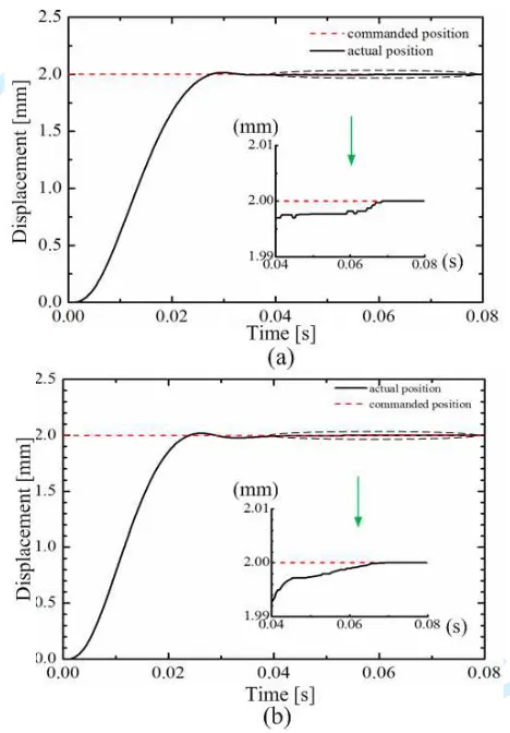
Fig.14 provides the step responses of X-axis and Y-axis tables. Based on the
simulation parameter values of the controller, the actual parameter tuning are
carried out. There are only four parameters to be tuned, and the control algorithm
is simple, thus reducing the calculation cost. Finally the parameter values are
For Peer Review
determined. For X-axis controller, Ka=0.6, KF=7, Kv=5 and Kp=16, and for Y-axis
controller, Ka=0.8, KF=8, Kv=5 and Kp=12. The ± 1.5 µm band at the desired level is
used as the acceptable range of variation from the desired response, and thus the X-axis
table settling time is found to be 64 ms, the overshoot is 0.7%. Y-axis table settling time
[image:23.612.189.423.215.551.2]is 62 ms, and the overshoot is 0.8%.
Fig.14 The step responses of the XY stage: (a) for X-axis, and (b) for Y-axis.
The parabola velocity response curves are shown in Fig.15. It can be concluded
that the actual position curves can match well with the command positions. The X-axis
dynamic position tracking errors are within ± 2.5 µm and the Y-axis dynamic position
tracking errors are within ± 4 µm. The simulation results are in a good agreement with
the experimental results, which proves the correctness of the theoretical model.
For Peer Review
Fig.15 The parabola velocity response curves: (a) X-axis displacement, (b) Y-axis displacement, (c)
X-axis velocity, (d) Y-axis velocity, (e) X-axis acceleration, and (f) Y-axis acceleration.
For the positioning accuracy and repeated positioning accuracy, the ISO
standard for the XY stage of machine tools is adopted, and it is measured using the
RENISHAW laser interferometer, and then the data is processed using
RENISHAW software. Motion range of 12 mm is divided into six segments by seven
points. When the table moves with the step size of 2 mm, laser interferometer measures
the displacement errors of the seven points, and five motion cycles are operated, and
For Peer Review
thus ten displacement errors are recorded in all at every point. Thus, the positioning
accuracy and repeatability of the X-axis and Y-axis can be obtained using the recorded
data. The recorded data are plotted in Fig.16. Forward stroke displacement error curve is
expressed by continuous line, and backward stroke displacement error curve is
described by dashed line. The results indicate that X-axis positioning accuracy is 1.75
µm, and the repeatability is 0.9 µm. Y-axis positioning accuracy and repeatability are 1.5
µm and 0.8 µm, respectively.
Fig.16 The positioning accuracy and repeatability: (a) for X-axis; and (b) for Y-axis.
The X- and Y-axes positioning accuracy has been simultaneously measured
across the entire workspace. The results show that X-axis positioning accuracy is
1.85 µm, and the repeatability is 0.95 µm. Y-axis positioning accuracy and 3
For Peer Review
repeatability are 1.75 µm and 0.9 µm, respectively.The main performance indexes of the XY stage are tested and summarized in Table
[image:26.612.105.512.186.260.2]1.
Table 1 The main performance indexes of the XY stage
Repeating positioning accuracy (µm)
Maximum speed (m/s)
Resolution (µm)
Motion stroke (mm)
X-axis 0.95 0.45 0.5 50
Y-axis 0.9 0.62 0.5 50
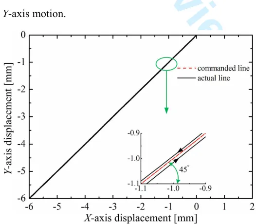
2-DOF trajectory tracking experiments have also been performed to investigate the
tracking performance of the XY stage, and the dynamic tracking errors of all the
points is used to describe the trajectory tracking performance of the XY stage.
Figure 17 plots the tracking results of the linear trajectory with an obliquity of 45°.
From Fig.17, it is seen that the actual trajectory almost coincides with the desired
trajectory, and there is a little delay of Y-axis motion compared with X-axis motion in
the positive motion, while in the negative motion, there is a little delay of X-axis motion
compared with Y-axis motion.
Fig.17 The tracking results of the linear trajectory.
[image:26.612.174.437.466.696.2]For Peer Review
Planar circular trajectories are also chosen as the desired trajectories, and the
displacements of the stage with different displacement commands are plotted in Fig.18,
where the diameters of the two command circles are 16 mm and 4 mm, respectively. It
is known from Fig.18 that the actual trajectories can track the desired circular
trajectories well, and the result shows that the X-axis dynamic position tracking errors
are within ± 2.5µm and the Y-axis dynamic position tracking errors are within ± 3.0 µm.
The capability of tracking more complex trajectory is further examined, and the
following smooth trajectory is chosen as the reference trajectory.
(
)
( )
4 sin 0.5 2 sin(8 0.5 )
4 sin 2 sin(8 )
r
r
x t t
y t t
π π π π
π π
= − + −
= + (37)
where xr, yr are the X- and Y- axes command displacements, respectively, and t is time.
The trajectory tracking result is displayed in Fig.19, which shows that the stage can
track the smooth trajectory well. During the motion process, the X-axis dynamic
position tracking errors are within ± 2.5µm and the Y-axis dynamic position tracking
errors are within ± 3.5 µm.
Fig.18 The tracking results of different reference circular trajectory.
For Peer Review
Fig.19 The trajectory tracking of the smooth trajectory.
5 Conclusions
To improve the quality and efficiency of semiconductor packaging, the dynamic
modeling, controller design and experimental tests of a LVCM direct-drive XY
positioning stage are carried out in this paper. Based on the characteristics of the
servomechanisms of the XY stage, the bond graphs of the stage are established, and the
state space equations are obtained. The controller based on force compensations is
proposed to control the XY stage, and it is realized through transforming the forces that
applied to the VCM coil and tables to the control voltage signals. The performance of
the XY stage are evaluated by experimental tests. The results show that when the
reference displacements are defined as 2 mm, the settling time of the X-axis movement
is 64 ms, and the overshoot is 0.7%. Y-axis settling time is 62 ms, and the overshoot is
0.8%. X-axis positioning accuracy is 1.85 µm, and the repeatability is 0.95 µm. Y-axis
positioning accuracy and repeatability are 1.75 µm and 0.9 µm, respectively. The linear,
circular and complex curve trajectory experimental results indicate the trajectory
For Peer Review
tracking performance of the XY stage are very well.
Acknowledgements
The supports of this work by the National Natural Science Foundation of China
(Grant no. 51205279 and 51175372), and the Science & Technology Commission of
Tianjin Municipality (Grant no. 13JCQNJC04100), the Tianjin University for Peiyang
Elite Scholar (Grant no. 60301014) and CSC Scholarship are gratefully acknowledged.
References
1 Adamy J, Flemming A (2004) Soft variable-structure controls: A survey.
Automatica 40:1821-1844
2 Aized T, Shirinzadeh B (2011) Robotic fiber placement process analysis and
optimization using response surface method. Int J Adv Manuf Technol 55:393-404
3 Ang K H, Chong G, Li Y (2005) PID control system analysis, design, and
technology. IEEE Trans Control Syst Technol 13:559-576
4 Cai T, Zhang M, Zhu Y, Hu C (2011) Dynamic modeling and analysis of a 3-DOF
ultra-precision positioning stage with air bearing. Procedia Eng 16:264-270
5 Dejima S, Gao W, Katakura K, Kiyono S, Tomita Y (2005) Dynamic modeling,
controller design and experimental validation of a planar motion stage for precision
positioning. Precis Eng 29:263-271
6 Fatikow S, Eichhorn V, Stolle, C, Sievers T, Jahnisch M (2008). Development and
control of a versatile nanohandling robot cell. Mechatronics. 18(7):370-80.
7 Ferreira P M, Qing Y, Dong J (2007) Design, analysis, fabrication and testing of a
parallel-kinematic micropositioning XY stage. Int J Mach Tools Manuf 47:946-961
8 Fung R-F; Hsu Y-L, Huang M-S (2009) System identification of a dual-stage XY
precision positioning table. Precis Eng 33:71-80
For Peer Review
9 Hace A, Jezernik K, Curk B, Terbuc M (1998) Robust motion control of XY table
for laser cutting machine. Proceedings of the 1998 24th Annual Conference of the
IEEE Industrial Electronics Society, Aachen, Germany, pp 1097-1102
10 Hwang J, Park C-H, Kim S-W (2010) Estimation method for errors of an aerostatic
planar XY stage based on measured profiles errors. Int J Adv Manuf Technol
46:877-883
11 Khan M U, Bencheikh N, Prelle C, Lamarque F, Beutel T, Buttgenbach S (2012) A
long stroke electromagnetic XY positioning stage for micro applications. IEEE
ASME Trans Mechatron, 17(5): 866-875
12 Li YM, Xu Q S (2011). A novel piezoactuated XY stage with parallel, decoupled,
and stacked flexure structure for micro-/nanopositioning. IEEE Trans Ind Electron.
58:3601-3615
13 Li Y M, Xu Q S (2012) Design and robust repetitive control of a new
parallel-kinematic XY piezostage for micro/nanomanipulation. IEEE/ASME Trans
Mechatronics, 17(6): 1120-1131
14 Liang Q, Zhang D, Song Q, Ge Y (2010) Design of a compliant XY stage with
embedded force sensor for micro-scale positioning. Proceedings of 2010 IEEE
International Conference on Information and Automation, Harbin, China, pp
1494-1499
15 Liaw HC, Shirinzadeh B, Smith J (2008). A Robust motion tracking control of
piezo-driven flexure-based four-bar mechanism for micro/nano manipulation.
Mechatronics. 18(2):111-20.
16 Liu Z Z, Luo F L, Rahman M A (2005) Robust and precision motion control system
of linear-motor direct drive for high-speed X-Y table positioning mechanism. IEEE
Trans Ind Electron 52:1357-1363
For Peer Review
17 Liu Z Z, Luo F L, Rashid M H (2003) QFT-based robust and precision motion
control system for a high speed direct-drive XY table positioning mechanism.
Proceedings of the IEEE Industry Applications Conference, UT, USA, pp 293–300
18 Mou S-C, Sung C-H (2012) Fuzzy positioning control of the novel single-axis
piezoelectric actuated stage. Proceedings of 2012 International Symposium on
Computer, Consumer and Control, Taichung, Taiwan, pp 771-776
19 Sanchez-Salmeron A J, Ricolfe-Viala C (2012) A flexible packaging station for
micro-bulk-forming applications based on a standard carrier. Int J Adv Manuf
Technol 61:529-536
20 Sun L, Li T, Liu Y (2011) Modeling and analysis of a high acceleration and
precision linear motor direct drive motion stage with bond graph approach. Robot
33:467-474
21 Teo C S, Tan K K, Lim S Y, Huang S, Tay E B (2007) Dynamic modeling and
adaptive control of a H-type gantry stage. Mechatronics 17:361-367
22 Tian Y, Shirinzadeh B, Zhang D (2009) A flexure-based mechanism and control
methodology for ultra-precision turning operation. Precis Eng 33:160-166
23 Tomizuka M (1987) Zero phase error tracking algorithm for digital control. J Dyn
Syst Meas Control Trans ASME 190:65-68
24 Wang F, Li J, Liu S, Zhao X, Zhang D, Tian Y (2014) An improved adaptive
genetic algorithm for image segmentation and vision alignment used in
microelectronic bonding, IEEE/ASME Transactions on Mechatronics. 19(3):
916-923
25 Wang F, Zhao X, Zhang D, Ma Z, Jing X (2011) Robust and precision motion
control for a directly driven XY table, Proceedings of IMechE, Part C, Journal of
Mechanical Engineering Science. 225(5): 1107-1120
For Peer Review
26 Wang F, Zhao X, Zhang D, Wu Y (2009) Development of novel ultrasonic
transducers for microelectronics packaging, Journal of Materials Processing
Technology. 209(3): 1291-1301
27 Wang W, Shin D, Han C, Choi H (2009) Modeling and simulation for dual stage
system using bond graph theory. Proceedings of International Symposium on
Optomechatronic Technologies, Istanbul, Turkey, pp 197-202
28 Wang Y, Xiong Z H, Ding H (2006) Robust controller based on friction
compensation and disturbance observer for a motion platform driven by a linear
motor. Proc IMechE Part I: J Syst Control Eng 220:33-39
29 Wu Y T, Ding H (2007) Reference adjustment for a high-acceleration and
high-precision platform via A-type of iterative learning control. Proc IMechE Part I:
J Syst Control Eng, 221:781-789
30 Xu L, Yao B (2000) Coordinated adaptive robust contour tracking of
linear-motor-driven tables in task space. Proceedings of the IEEE Conference on
Decision and Control, Sydney, Australia, pp. 2430-2435
31 Xu Q S, Li Y M (2009) Radial basis function neural network control of an XY
micropositioning stage without exact dynamic model. Proceedings of 2009
IEEE/ASME International Conference on Advanced Intelligent Mechatronics,
Singapore, pp. 498-503
32 Zhang H, Wang F, Zhao X, Zhang D, Tian Y (2013) Electrical matching of a
piezoelectric ultrasonic transducer for microelectronic bonding, Sensors and
Actuators A: Physical. 199(1): 241-249
33 Zhao Y, Yang K, Zhu Y, Pan S (2010) Modeling and analyzing of an H-drive
precision XY stage. Proceedings of 2010 International Conference on Mechanic
Automation and Control Engineering, Wuhan, China, pp 6311-6314
For Peer Review
APPENDIX
Notation
ar acceleration of VCM coil
C capacitor element
C1 damping between coil and the guiding fin
C2 equivalent damping between the Y-axis guiding fin and table
e effort
f flow
F force generated by the VCM
Fc coulomb friction
Fd damping force
Fdy Y-axis damping force
FF1 friction of the X-axis coil
FF1y friction of the Y-axis coil
FF2 friction of the X-axis table
FF2y friction of the Y-axis table
Fi1 inertia force of the X-axis coil
Fi1y inertia force of the Y-axis coil
Fi2 inertia force of the X-axis table
Fi2y inertia force of the Y-axis table
FL output force of the coil
Fs equivalent spring force
Fst static friction
Fsy Y-axis equivalent spring force
Ga(s) transfer function of the inertia force
Gc(s) transfer function of current loop PID controller,
Gf(s) transfer function of friction compensator
Gv(s) transfer function of damping force compensator
Gp(s) transfer function of spring force compensator
GLR(s) equivalent transfer function of the VCM
i current intensity through the coil
Im current of VCM coil
For Peer Review
K stiffness of the preload spring
K1 connecting stiffness between coil and the guiding fin
Kc contact stiffness between the bearing and the lapping plate
1/Ki current conversion factor
Ks gain of the PWM driver
Kt stiffness of the flexure hinge
Kv0 velocity feedback coefficient
Kv1 velocity gain of VCM coil
KB coefficient of inducted electromotive force
KF force coefficient.
Lm inductance of the VCM coil
M1 equivalent mass of the Y-axis guiding fin
M2 equivalent mass of the Y-axis table
M3 mass of the X-axis table
Mr mass of the coil
p(t)) time integral of effort
q(t) time integral of flow
R resistor elements
Rm resistance of the VCM coil
s differential operator
Se effort source
Ts time constant
ux input variable
U voltage applied to the VCM
Ua control voltage of the inertia force
Uc input control voltage
Uf control voltage of friction compensator
UB back electromotive force of the VCM coil
Um operating voltage of VCM coil
v motion velocity of the VCM coil
v2 velocity feedback
vf velocity
vs Stribeck velocity
x displacement of X-axis table