warwick.ac.uk/lib-publications
A Thesis Submitted for the Degree of PhD at the University of Warwick Permanent WRAP URL:
http://wrap.warwick.ac.uk/94058
Copyright and reuse:
This thesis is made available online and is protected by original copyright. Please scroll down to view the document itself.
Please refer to the repository record for this item for information to help you to cite it. Our policy information is available from the repository home page.
1
WMG, UNIVERSITY OF WARWICK
FE simulation of the SPR process to
predict joint characteristics
Engineering Doctorate Portfolio:
Innovation Report
by
Mario Carandente
2
Abstract
Self-pierce riveting (SPR) is the core joining technology used by Jaguar Land Rover (JLR) to
join aluminium & mixed material body in white (BIW). Currently, the application of this
process has a serious constraint to the business due to the high investment and intensive
labour required by physically testing joint feasibility. This is a critical issue especially where
different stacks need to be joined by one SPR gun. In this case, the selection of a common
rivet/die combination which suits different material stacks requires labour intensive work that
in some cases can create long delays during a vehicle development and commissioning. In
this context, the development of a simulation technique, based on Finite Element Analysis
(FEA), could allow virtual assessment of the manufacturing feasibility of a joint. This will
enable significant business benefits including: saving time, costs and materials requirement
for the experimental trials.
Three major challenges need to be addressed: short CPU time, accuracy and robustness
in order for its application in a manufacturing environment. To achieve these objectives,
detailed numerical methods capable of reproducing the key factors affecting the experimental
process like tooling, boundary conditions and material plastic deformation are developed. For
the first time, a thermo-mechanical finite element model for simulation of the SPR process
has been proposed. This allowed consideration of the increase in temperature due to friction
and plastic deformation generated during the rivet insertion. The effect of thermal softening
and strain hardening were characterized for the development of the substrate material model
and their influence on the numerical simulation was assessed. This study has been validated
via production line data and a significantly high level of correlation between simulation and
experimental data for over 1000 joints representative of a vehicle platform has been achieved.
The application of the developed simulation technique will enable several business benefits
such as significant reduction of engineering time and costs in contrast to the experimental
procedure. These advantages allow a smooth implementation of the SPR process in a JLR
production line by providing engineering recommendations rapidly and consistently. All
these features, combined with accuracy and robustness have enabled the application of the
3
Declaration
4
Acknowledgements
I would like to express my deepest gratitude to my industrial supervisor Dr. Li Han for her support, guidance and mentoring during my study. I also would like to thank my academic supervisors Dr. Iain Masters, Prof. Barbara Shollock and Prof. Richard Dashwood.
Much gratitude to Mr. Mike Shergold for recruiting me in the EngD programme and to all my colleagues at Jaguar Land Rover in the AME joining department for their support. In
particular, I would like to say thank to Eddie Latimer and Dean Homewood for supporting me during the industrial trials.
5
Table of Contents
Abstract ... 2
Acknowledgements ... 3
1. Project background ... 12
1.1 Objectives of this research ... 13
1.2 Portfolio and structure of the report ... 14
2. Literature review ... 16
2.1 Introduction ... 16
2.2 Mechanical joining ... 19
2.2.1 Self-pierce riveting ... 19
2.3 Numerical simulation of the SPR process ... 22
3. Research methodology ... 25
4. Development of the Finite element models ... 30
4.1 Boundary conditions ... 30
4.2 Mesh parameters ... 32
4.3 Coefficient of fiction ... 38
5. Discovery of the thermo-mechanical behaviour for SPR simulation ... 41
5.2 Experimental Results ... 43
5.3 Comparisons between experimental and numerical temperature generated during the SPR process………46
5.4 Effect of Punch speed, friction coefficients and thermal conductivity on temperature profile ………50
6. Development of material models ... 56
6.1 AA5754 ... 56
6.1.1 True stress and strain curves ... 57
6.1.2 Calculation of flow curves ... 60
6.1.3 Effect of temeperature and strain rate on simulation results ... 63
6.2.4 Validation of the substrate material model ... 66
6.2 AC600T4... 74
6.2.1 True stress and strain curves ... 76
6.2.2 Calculation of flow curves ... 78
6.2.3 Effect of natural ageing on joint characteristics ... 81
6.2.4 Validation of the substrate material model ... 84
7. Validation of the developed technique using a JLR vehicle platform ... 90
6
7.2 Validation results ... 90
8. Industrial benefits and Research dissemination ... 95
9. Conclusions ... 99
10. Future work ... 100
7
List of Figures
Figure 1: Vehicle mass breakdown by system and components (Luytsey, 2010) ... 16
Figure 2: Body in white structure of the Jaguar XJ (2003) ... 17
Figure 3: Spot clinching process (Barnes and Pashby, 2000b) ... 19
Figure 4: Schematic representation of the SPR process (Voelkner, 2000) ... 20
Figure 5: A typical force-displacement curve for a SPR process (Hou et al., 2004) ... 20
Figure 6: Comparison between numerical and experimental cross-section and force vs displacement curve (Porcaro et al., 2006) ... 22
Figure 7: Effect of different friction coefficients on the equivalent plastic strain of aluminum rivet. (The dashed red line indicate the area where shear fracture might occur) (Hoang et al., 2013) ... 23
Figure 8: Final configurations for a) coarser mesh (minimum element size=0.2mm) and lower failure parameter (𝜀𝑝 = 1.1); b) finer mesh (minimum element size=0.066mm) and lower 𝜀𝑝; c) coarser mesh and higher 𝜀𝑝 (1.5); d) finer mesh and higher 𝜀𝑝. (Casalino et al., 2008) ... 24
Figure 9: Research pillars ... 25
Figure 10: Characteristics of a SPR joint cross-section ... 26
Figure 11. a) Experimental setup. b) Thermo-mechanical cycle of the tensile tests at high temperature ... 28
Figure 12. Comparison between true stress and true strain curves of AA5754 at ambient temperature and 0.01 s-1obtained with conventional cross-head displacement and Aramis system ... 28
Figure 13. a) Real C-frame b) Virtual C-frame... 31
Figure 14. Schematic view of the axisymmetric model including the external loads applied ... 32
Figure 15. Comparisons of different mesh sizes: a) Model 1, b) Models 2, c) Model 3, d) Model 4. Model 1 (a) and Model 4 (d) show interpenetration (circled) between elements of top and bottom sheets ... 33
Figure 16. Comparison of force vs displacement curves obtained with models 1, 2, 3 and 4 ... 34
Figure 17. Mesh refinement used for the numerical simulation of the SPR process ... 36
Figure 18. Rivet insertion at time steps before and after the erosion technique takes place: a) Tremoval = 0.02mm before erosion b) Tremoval = 0.02mm after erosion c) Tremoval = 0.1mm before erosion d) Tremoval = 0.1mm after erosion e) Tremoval = 0.2mm before erosion f) Tremoval = 0.2mm after erosion. ... 37
Figure 19. Comparisons of force vs displacement curves at Tremoval equal to 002mm, 0.1mm and 0.2mm ... 38
Figure 20. comparison of cross-section geometries. a) model 1 - µ = 0.09 at the interface between the aluminum sheets and µ = 0.15 at the interface between the bottom sheet and die. b) model 2 - µ = 0.15 at the interface between the aluminum sheets and µ = 0.22 a ... 39
Figure 21. Comparison between model 1 and 2. a) cross-section geometries b) force vs displacement curves ... 40
Figure 22: Thin layer of black paint applied on the lateral surface of SPR coupons ... 43
Figure 23: Experimental procedures a) Coupons placed on the top of the die before riveting. b) Coupons with rivet inserted on half section ... 43
Figure 24: Comparison of force vs displacement curves for full and half joints ... 44
Figure 25: Temperature profile during SPR insertion... 45
Figure 26: Area of peak temperature on SPR cross-section. a) IR image, b) experimental sample ... 45
Figure 27. Cross-section geometries. a) rivet. b) die ... 46
Figure 28. Temperature profile obtained with the numerical analysis ... 48
8
Figure 30. Comparison between experimental and numerical cross-section obtained with thermo-mechanical model ... 49
Figure 31. Comparison between force vs displacement curves of experimental and numerical model 49
Figure 32. Comparison between experimental and numerical cross-section obtained with isothermal model ... 50
Figure 33. Modelled temperature vs time curves of top layers ... 52
Figure 34. Modelled temperature vs time curves of bottom layers ... 53
Figure 35.Comparison of cross-section geometries obtained with different punch speed. a)v=50mms, b)v=200mm/s ... 55
Figure 36. Effect of friction coefficient on the deformation of rivet leg. a) µ=0.06, b) µ=0.12 ... 55
Figure 37. Effect of strain rate on the true stress vs true strain curves at different temperature: a) 25 ºC. b) 200 ºC. c) 250 ºC and d) 300 ºC. ... 58
Figure 38. Deterioration of the patter in the area of the neck ... 58
Figure 39. True stress vs true strain curves at strain rate of 0.01s-1, 0.1 s-1 and 1s1 including strain at fracture: a) 25 ºC. b) 200 ºC. c) 250 ºC and d) 300 ºC ... 59
Figure 40. Evolution of the strain at fracture as a function of strain rate and temperature ... 60
Figure 41. Flow curves at strain rate of 0.01s s-1, 0.1 s-1 and 1s-1: a) 25 ºC. b) 200 ºC. c) 250 ºC. d) 300 ºC. ... 61
Figure 42. Comparison between experimental and numerical cross-sectional geometries: a) Numerical simulation using data derived at room temperature and a strain rate of 1s-1. b) Numerical simulation using data derived at 25°C, 200°C, 250°C, 300°C and strain rate of 1s-1. ... 63
Figure 43. Effect of temperature on plastic deformation of rivet leg: a) Numerical model with only flow curve at room temperature and strain rate of 1s-1. b) Numerical model with flow curves at 25°C, 200°C, 250°C, 300°C and strain rate of 1s-1. ... 64
Figure 44. Comparison between numerical and experimental cross-sectional geometries: a) Numerical model with flow curve at temperatures of 25°C, 200°C, 250°C, 300°C and strain rate of 0.01s-1. b) Numerical model with flow curves at temperatures of 25°C, 200°C, 250°C, 300°C. ... 64
Figure 45. Effect of strain rate on plastic deformation of rivet leg: a) Numerical model with flow curve at temperatures of 25°C, 200°C, 250°C, 300°C and strain rate of 0.01s-1. b) Numerical model with flow curves at temperatures of 25°C, 200°C, 250°C, 300°C and strain rate of 1s-1. ... 65
Figure 46. a) Rivet cross-sectional shapes. b) Die geometries. c) Die cross-sectional shapes ... 67
Figure 47. Comparison between cross-sectional geometries of joint 1: (1.5mm+1.5mm) AA5754 .... 69
Figure 48. Comparison between cross-sectional geometries of joint 2: (1.2mm + 1.5mm) AA5754 .. 69
Figure 49. Comparison between cross-sectional geometries of joint 3: (2.0mm+2.0mm) AA5754 .... 69
Figure 50. Comparison between cross-sectional geometries of joint 4: (1.5mm+2.0mm) AA5754 .... 70
Figure 51. Comparison between cross-sectional geometries of joint 5: (1.5mm+1.5mm+2mm)
AA5754 ... 70
Figure 52. Comparison between cross-sectional geometries of joint 6: (1.5mm+2.5mm+2.5mm) AA5754 ... 70
Figure 53: Comparison of numerical (red lines) and experimental (blue lines) force vs displacement curves. a) joint 1, b) joint 2, c) joint 3, d) joint 4, e) joint 5, d) joint 6 ... 72
Figure 54. Overall comparison between experimental and numerical joint characteristics values: a) Interlock, b)Tmin ... 73
9
Figure 56: Time-Temperature profile for a solution treated and naturally aged alloy(Campbel, 2008).
... 75
Figure 57: Comparison of true stress vs true strain curves at strain rate of s-1 and age of 3 and 6 months: a) 25 ºC, b) 200 ºC, c) 250 ºC, d)300 ºC ... 77
Figure 58: True stress vs true strain curves at strain rate of 0.01s-1, 0.1 s-1 and 1s1 and 3 months age: a) 25 °C. b) 200 °C. c) 250 °C and d) 300 °C ... 78
Figure 59: Comparison of flow curve at 3 and 6 months age: a) 25 ºC. b) 200 ºC. c) 250 ºC. d) 300 ºC. ... 78
Figure 60: Effect of natural ageing and testing temperature on fracture morphology. a) 3 months, b) 6months ... 79
Figure 61: Effect of natural ageing on Tmin values for joint 1 (2.5mm AC600T4 + 2.5mm AC600T4) ... 82
Figure 62: Effect of natural ageing on Interlock values for joint 2 (2mm AA5754 + 2.5mm AC600T4) ... 83
Figure 63: SPR cross section geometries for stack 1 at: a) month 3 and b) month 6 ... 83
Figure 64: SPR cross section geometries for stack 2 at: a) month 3 and b) month 6 ... 84
Figure 65: Comparison of numerical SPR joint characteristics for stack 1: a)month 3 and b) month 6 ... 85
Figure 66: Comparison of numerical SPR cross-sections at 3 and 6 months for stack 1 ... 86
Figure 67. Comparison between numerical and experimental results for stack 1 showing gaps between rivet leg and substrate material (1) and top and bottom sheet (2) ... 86
Figure 68: Comparison of numerical SPR joint characteristics for stack 2: a)month 3, b) month 6 .... 87
Figure 69: Comparison of numerical SPR cross-sections at 3 and 6 months for stack 1 ... 88
Figure 70: Fitted line plot obtained from the linear regression model between Interlock numerical and Interlock experimental ... 92
Figure 71: Fitted line plot obtained from the linear regression model between Tmin numerical and Tmin experimental ... 93
Figure 72: Residual plots for interlock. a) Versus order, b) Normal probability plot ... 93
Figure 73: Residual plots for interlock. a) Versus order, b) Normal probability plot ... 94
Figure 74: Normal distribution of Interlock residual ... 94
Figure 75: Normal distribution of Tmin residual ... 95
Figure 76: Time flow with experimental method ... 96
Figure 77: Time flow with simulation method ... 96
10
List of Tables
Table 1: Portfolio submissions and correlation with the sections in this document ... 15
Table 2. Proof strength of rivets... 29
Table 3. Mesh sizes used for comparisons ... 32
Table 4: List of mesh parameters used in the literature for SPR simulation ... 35
Table 5: List of mesh parameters used in the literature for SPR simulation ... 40
Table 6: Thermal conductivity and specific heat capacity used in the FE model (Smithells, 1990). ... 47
Table 7. Input parameters for numerical simulations ... 51
Table 8: List of joint characteristics and peak temperatures for the seven models ... 54
Table 9: Nominal composition of AA5754 in wt% ... 56
Table 10. Experimental parameters used for tensile testing ... 57
Table 11. Experimental parameters determined from tensile testing ... 62
Table 12. Joint variables ... 66
Table 13. Comparisons between experimental and numerical joint characteristics values ... 71
Table 14. Nominal composition of AC600 T4 in wt% ... 74
Table 15: Experimental parameters used for tensile testing ... 76
Table 16. Experimental parameters determined from tensile testing ... 80
Table 17. List of SPR stacks ... 81
Table 18: Comparisons between numerical and experimental joint characteristics ... 88
Table 19: Coefficients A and B obtained from the linear regression model for both Interlock and Tmin ... 91
11
Abbreviations
SPR
Self-pierce riveting
JLR
Jaguar Land Rover
FEA
Finite Element Analysis
BIW
Body in white
DIC
Digital image correlation
RSW
Resistance spot welding
AB
Adhesive bounding
12
1.
Project background
Joining materials has always been considered one of the most critical aspects of a
manufacturing process. In the most common definition, a joining process consists in bringing
together similar or dissimilar materials in order to create a continuous body or a unit
(Messler, 2004). Nowadays, the development of new materials is pushing toward the
application of new joining technologies. The latter is extremely important for the automotive
industry which is currently focussed on lightweight vehicles to enhance both fuel efficiency
and driving performance. Weight saving is normally achieved by replacing current high
density materials, mainly used for the automotive BIW structures, with light-weight materials
such as aluminium alloys, magnesium alloys, high strength low alloy steels and carbon fiber
reinforced plastics (Mayyas et al., 2011). However, the substitution of conventional steel with light-weight materials requires the development of new joining technologies. Even though
spot welding is recognized as the conventional joining technology for the BIW assembly,
several issues have been observed when welding light-weight materials such as aluminium
alloys. Therefore, in order to allow the development and the subsequent application of new
materials, developing new ways of joining is of primary importance for the automotive
industry.
SPR has been the core joining technology for JLR lightweight vehicle manufacturing since
2003. Although, this technology has been also employed by several OEM’s due to the
capability of joining dissimilar metals with different surface coatings, the implementation of
this process in a large scale production environment can be a serious constraint to the
business. The main challenge of the SPR process is the requirement of a fixed rivet/die
combination for a specific material stack owing to the inflexibility of changing rivet and die
during application. Moreover, due to the demands for slower cycle time, reduced capital
investment and design requirements for more materials and thicknesses flexibility, different
stacks made of different material grades and thicknesses need to be joined by the same SPR
gun. As a result, extensive experimental trials need to be conducted in order to assess the
feasible rivet/die combinations and to assign the right combination to a BIW assembly
facility. In addition, the lack of reliable non-destructive tests (NDT) makes the experimental
trials even more labour intensive and prone to inaccuracy due to the necessity of
cross-sectioning and subsequent measurements of joint characteristics. This has always presented
13
delay engineering decisions, the demands in investment for equipment, materials and labour
resource, etc. Therefore, having a virtual tool, which enables simulation of the SPR process
and prediction of the joint characteristics, will allow reduction in investment costs and
engineering time together with a smother implementation of the SPR process in a production
line.
1.1 Objectives of this research
The aim of this study is to develop a simulation technique capable of simulating the plastic
deformation during the SPR process and of producing cross-sections of the joints for
prediction of joint characteristics.
The model must address three major challenges in order to enable its application in a
manufacturing environment: short CPU time, accuracy and robustness.
To allow a short CPU time which is at least comparable with the time required for
experimental testing, investigation of suitable mesh sizes and re-meshing techniques are
required.
To enable accuracy, the development of detailed numerical methods, capable of reproducing
the key parameters affecting the experimental process such as boundary conditions, tooling
and material plastic deformation is required. Finally, in order to prove the robustness of the
developed simulation technique, its validation needs to be provided based on a JLR vehicle
platform in order to reflect the large variety of different rivet/die combinations and stack
configurations typical of BIW assembly complexity.
To achieve these objectives, the following items have to be addressed:
Development of boundary condition for FEA simulation
Development of mesh parameters and friction coefficients
Development of material models
14
1.2 Portfolio and structure of the report
Chapter 1 has discussed the motivation and industrial relevance of this Engineering Doctorate
project.
Chapter 2 provides a brief literature review on the conventional joining technologies used in
automotive industry with focus on SPR and the current methods developed for the FE
simulation.
Chapter 3 states the methodology used in this research.
Chapter 4 discusses the development of the finite element models with respect to input
parameters such as boundary conditions, mesh parameters and friction coefficients.
Chapter 5 describe the application of a thermo-mechanical analysis for SPR simulation.
Chapter 6 investigates the development of material models for AA5754 and AC600T4
aluminium alloys
Chapter 7 reports the validation of the simulation technique using a JLR vehicle platform
Chapter 8 states the business benefits and dissemination of this research
Chapter 9 and 10 provides the conclusions and proposed future work
15
Table 1: Portfolio submissions and correlation with the sections in this document
Submission N°
Portfolio Submission Title Innovation report section
1 Literature review: Introduction to Self-Pierce riveting
and finite element analysis
1,2
2 Development of a finite element method for simulation
of the SPR process
4,6
3 Experimental and numerical investigation of the
temperature generated during the SPR process
5
4 Improvement in numerical simulation of the SPR process
using thermo-mechanical finite element analysis
(published in Journal of Material Processing Technology)
4,6
5 Experimental and numerical investigation on the
rivetability of a 6xxx – T4 aluminium alloy
6
6 Innovation Report
16
2.
Literature review
2.1 Introduction
Due to environmental concerns, the automotive industry has been pushed toward a global
challenge that involves the reduction of fuel consumption and carbon dioxide emissions while
keeping customer expectations. In this context, the use of lightweight materials to reduce
vehicles mass has been considered one of the most effective solutions (Davies, 2012a).
As reported by (Mayyas et al., 2011) a weight reduction of 10% can guarantee an improvement of 5% in terms of fuel efficiency. Therefore, as BIW and closures account for
more than 30% of the total vehicle weight (Figure 1), these represent the principal areas
where the automotive industry is mainly focused to guarantee a significant weight reduction.
Figure 1: Vehicle mass breakdown by system and components (Luytsey, 2010)
However, the selection of lightweight materials in a vehicle BIW is not a trivial aspect; it
may require not only different approaches on the vehicle design but also new manufacturing
technologies including new joining methods (Mori et al., 2013). In this context, JLR has been one of the leading car manufacturers using aluminium alloys for its body structures since
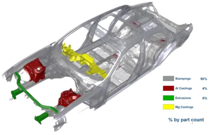
2003 when the first aluminium Jaguar XJ was launched. As shown in Figure 2, the BIW of
the Jaguar XJ is characterized by 90% of aluminium stamping parts which are made of 5xxx
and 6xxx series aluminium alloys. Aluminium castings and extrusions were also used
respectively for the shock towers and front beams whilst a magnesium casting was used for
the dash structure. Despite the aluminium architecture enabling significant weight savings in
17
terms of joining processes for the BIW assembly. A new joining method based on the
combination of SPR and adhesive bounding was adopted. Nowadays, this technology
[image:18.595.138.475.179.395.2]represents the main joining process employed by JLR to assemble its aluminium BIW.
Figure 2: Body in white structure of the Jaguar XJ (2003)
It is clear that the introduction of lightweight materials in the automotive BIW has triggered
the requirement for development of new joining technologies compatible with the new
vehicle design. The three fundamental processes that allow the joining of material and
structures are welding, adhesive bonding and mechanical joining.
Among the welding technologies, Resistance spot welding (RSW) is certainly the most
common joining process used in BIW applications.
Despite this process being well established for steel, some issues have been found in welding
of aluminium BIW. These issues are related to the experimental and chemical properties of
aluminium alloys. One is the chemical reaction of aluminium with oxygen in atmosphere. As
a result, the formation of an oxide layer, Al2O3, takes place on the metal surface. The latter
protects the metal from corrosion but, due to its higher melting temperature compared to the
bulk metal, the removal of this film (Han et al., 2010) or regular electrode polishing are needed to allow weld formation to take place (Boomer et al., 2003). Moreover, due to the experimental properties of aluminium alloys such as low electrical and thermal resistivity,
18
the welding current required to spot weld aluminium alloys is about two times greater than
steel. Moreover, the electrode life for aluminium alloy spot welding is 2.5 to 5 times lower
compared with the electrode life for the spot-welding of mild steel (Ambroziak and
Korzeniowski, 2010). Although several researchers have shown that the spot welding of
aluminium alloys can guarantee good joint performance, the different requirements on current
and electrode life make the process used for steel spot welding, unlikely to be used for
aluminium spot welding. Therefore, the application of aluminium spot welding in a large
scale vehicle production is still a challenge.
Adhesive bonding (AB) is a joining technology based on the application of adhesive at the
interface of the materials to be joined. The main advantages of adhesive bonding are: the
more uniform stress distribution, the possibility to gain a lighter structure due to the
elimination of mechanical fasteners such as rivets and the prevention of electrochemical
corrosion in joint between dissimilar metals (Michalos et al., 2010). The main applications of adhesive bonding in automotive industry concern the non-structural parts, however its
application to sheet components for load-bearing parts is now increasing (Davies, 2012b)
(Campbell, 2006). For instance, adhesive bonding can be used in combination with resistance
spot welding or self-piercing riveting. A hybrid joint of adhesive bonding and RSW or SPR
allows a sealed connection, the ability to damp noise and vibrations and a good fatigue
resistance (Michalos et al., 2010), (Di Franco et al., 2013). Despite AB offering advantages in the form of hybrid joint, its application as a stand-alone process is still not possible, as in
many cases, changing to adhesive would also require substantial change of the bill of the
process. Moreover, the long-term durability of the adhesives is still not fully understood
(Meschut et al., 2014).
Due to the difficulties in welding aluminium alloys and mixed metal joints and limitation of
AB as stand-alone process, mechanical joining has been the key technology to join
19
2.2 Mechanical joining
The use of mechanical joining technologies in automotive BIW has increased over the last
decades due the possibility of joining aluminium alloys and mixed metals with different
surface coatings. Indeed, mechanical joining only involves mechanical forces that arise from
interlocking between the panels. Mechanical joining technologies like SPR and clinching are
well established in many automotive production lines. Unlike conventional riveting systems
like blind riveting, these technologies offer the advantage of no pre-drilled hole requirement
which enables saving time and hole misalignment issues. Figure 3 shows the steps of a
clinching process and emphasizes that, differently from the SPR, the technique is only based
on a punch to form the material into a die without use of rivets.
Figure 3: Spot clinching process (Barnes and Pashby, 2000b)
Despite clinching and SPR offering the capability of being applied to dissimilar materials, the
main disadvantages of the two processes are the double-sided access and the quite large
setting force which requires for a stiff C-Frame structure capable of withstanding the riveting
force (Barnes and Pashby, 2000b).
2.2.1 Self-pierce riveting
SPR is “allegedly” a cold joining method that enables the joining of two or more materials by
creating a mechanical interlock between the rivet and the substrate materials. As shown in
Figure 4, the process is characterized by four successive steps: (I) clamping, (II) piercing,
20
with the top sheet; the rivet then breaks through the top sheet and flares into the bottom sheet.
Finally, the punch is released when reaching the value of the force or displacement given as
an input. Figure 5 shows these four steps in relation to a typical force-displacement curve
measured during the riveting process (Hou et al., 2004). This curve is usually used for process monitoring, since its shape is a characteristic of each SPR joint (He et al., 2006). King (1997) conducted a detailed study on the quality monitoring of the SPR process with
reference to the behaviour of the force-displacement curve. It was observed that the shape of
the curve is affected by rivet geometry, substrate material grade and thickness and die
geometry (King, 1995).
Figure 4: Schematic representation of the SPR process (Voelkner, 2000)
Figure 5: A typical force-displacement curve for a SPR process (Hou et al., 2004)
The increased application of SPR has been justified by several advantages including: no
predrilled hole requirements, the possibility of joining different metals with dissimilar surface
21
comparable cycle-time with spot welding, and no fume emission which makes the process
environmentally friendly (Chrysanthou, 2014). Several researchers have discussed the
behaviour of a SPR joint under fatigue and quasi-static loading. SPR showed improved
fatigue life (Booth, 2000), and lap-shear strength in comparison to RSW (Han et al., 2009). However, in order to achieve the optimum joint performance, detailed investigation of the
process parameters like rivet length, die design and rivet surface coating are required.
Moreover, it was found that the presence of adhesive could provide significant increase in
joint strength and energy absorption under the lap-shear condition (Stephens, 2014).
The comparable mechanical properties with RSW and the several advantages offered, have
made the SPR process one of the main technologies to join aluminium and mixed metal BIW
structures.
Audi was the first automotive manufacturer employing SPR as a joining process with its
aluminium space frame technology in 1993. The Jaguar XJ (2004) used 3118 rivets in a
monocoque vehicle where it was estimated that the overall weight of rivets was about 3Kg
and the cost of each rivet is roughly £ 2 cents which gives a total cost of $100 per vehicle
(Mortimer, 2001). Volvo utilized the SPR for its FH12 truck, where 42 rivets per cab were
used to join high strength steel sheets (He et al., 2006). The recent application of SPR into the Ford F150 truck represents the first wide-scale application of SPR in a high volume
production which involves the assembly of 60 units per hour (Weber, 2015).
Although, the application of SPR can lead to performance benefits in comparison to the
conventional RSW, its application might be more critical from the economic perspective. A
cost comparison between self-piercing riveting, resistance spot welding and friction stir spot
(FSW) welding for high volume aluminium BIW was undertaken by (Briskham et al., 2006). The study showed that, although, SPR would require lower electricity costs, its consumable
costs (rivets) would be significantly higher.
Despite the recent developments in the SPR process, further improvements are required to
enable its application on new emerging materials such as high strength steel, aluminium
castings and composite materials. Moreover, the inability of changing rivet and die
combinations during the process and the lack of non-destructive testing techniques present a
serious constraint for a smooth implementation of the process in a high volume production
environment. Therefore a simulation technique capable of simulating the process and to
22
2.3 Numerical simulation of the SPR process
Many researchers have investigated the simulation of the SPR process using different
commercial finite element packages. A detailed review of the FE models developed for
simulation of the SPR process was provided by (He, et al., 2012).
Porcaro et al. (2006) developed a 2D axisymmetric simulation for a single rivet specimen where the variables of the model were thickness and material properties of the top and bottom
substrate materials (Figure 6). An r-adaptivity method was implemented to deal with the large
plastic deformation which occurred during the SPR process. Bouchard et al. (2008) used Forge 2005 finite element software to simulate the mechanical fields such as damage,
residual stresses and strains occurring during the SPR process. Hoang et al. (2011) used a 3D model to simulate the joint strength by taking into account the effect of straining occurring
from the riveting process and the increase in work-hardening due to natural ageing of the
substrate materials AA6063 – W.
Figure 6: Comparison between numerical and experimental cross-section and force vs displacement curve (Porcaro et al.,
2006)
Hoang et al. (2010) provided a numerical analysis using aluminium SPR rivets. Successful joints were obtained by adjusting the strength of the aluminium rivet through heat treatment
and by optimizing the die shape. Mori et al. (2006) used the LS-Dyna finite element code to
simulate the joining of ultra-high strength steel to aluminium alloy. Defects like rivet
23
Mucha (2011) used Marc finite element software to analyse the effect of different variables
on SPR quality parameters. The variables under investigation were: rivet proof strength, die
impression profile and friction coefficients. The results showed that rivet strength and die
profile had significant influence on the setting force and rivet spreading whilst marginal
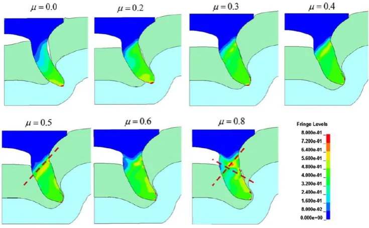
variation in setting force was observed by increasing of friction coefficients. Hoang et al. (2013) studied the effect of the friction coefficients on the strain localization at critical area of
a AA7278 – T6 rivet. The author found that the friction coefficient between rivet and
substrate materials had a significant effect on the compression of the rivet leg. Indeed, by
increasing of friction coefficient, higher compression of the rivet leg was obtained. Moreover,
it was observed that friction coefficients between 0.6 and 0.8 lead to strain localization along
[image:24.595.105.473.313.540.2]two perpendicular directions which indicated the potential cause of shear fracture (Figure 7).
Figure 7: Effect of different friction coefficients on the equivalent plastic strain of aluminum rivet. (The dashed red line indicate the area where shear fracture might occur) (Hoang et al., 2013)
The piercing process has often been simulated with a geometric failure criterion in which
element removal takes place when the local thickness of the pierced sheet reaches a user
defined critical value. An alternative method was provided by Casalino et al. (2008) in which, the failure of the upper sheet was modelled by imposing an effective plastic strain at
fracture combined with the erosive Kill-element technique. However, in order to reduce the
volume loss due to the erosion technique, finer mesh and higher effective plastic strain at the
24
Figure 8: Final configurations for a) coarser mesh (minimum element size=0.2mm) and lower failure parameter (𝜀𝑝= 1.1);
b) finer mesh (minimum element size=0.066mm) and lower 𝜀𝑝; c) coarser mesh and higher 𝜀𝑝 (1.5); d) finer mesh and
higher 𝜀𝑝. (Casalino et al., 2008)
Fayolle (2006) used the Lemaitre coupled damage model to simulate the piercing of the top
sheet. In this model, the damage evolution during the rivet insertion influences the
mechanical properties of the material and element removal takes place when the damage
parameter reaches a critical value. However, its application is mesh sensitive and requires a
very fine mesh for correct simulation of the element deletion.
While previous studies provided some insight into simulation of the SPR process, attention
was mainly focussed on the structural behaviour of the joint or optimisation of the rivet and
die geometry. None of the previous research has developed a simulation tool capable of
predicting joint characteristics for complex industrial applications. In addition, the
development of detailed boundary conditions and material models representative of the real
process were often underestimated. For instance, as discovered in this study, accounting for
the effect of thermal softening of the substrate materials due to plastic deformation and
friction contacts is key for accurate simulation of the SPR process. Additionally, models
have often only been validated against a small number of joint combinations and the
25
3.
Research methodology
The ultimate objective of this research is to develop a simulation technique which requires
short CPU, accuracy and robustness to enable applications in a manufacturing environment.
The structure of this research methodology is characterized by four main pillars as indicated
in Figure 9:
Figure 9: Research pillars
1. Problem definition and understanding of industrial requirements:
The common procedure used in the automotive industry to assess the feasibility of a SPR
joint is based on experimental testing of coupon materials and subsequently cross-sectioning
for measuring of the joint characteristics. A schematic of a SPR cross section is shown in
Figure 10. In general, three geometric parameters are measured to assess joint feasibility:
Head height – this measures the depth to which the rivet is inserted into the material.
In general, during coupon testing the setting parameters of the SPR gun (e.g. velocity/ Problem definition and
understanding of industrial requirements
Model development
Embodiment of the model
26
end position) are chosen in order to achieve a rivet head sitting flush with the surface
of the top layer.
Interlock – this measures how much the rivet legs spread into the bottom layer of the
joint
Remaining thickness (Tmin) – this measures the thinnest gauge of the bottom layer
achieved after the riveting process
Other factors that need to be checked are rivet cracking / buckling, cracking of the substrate
materials and gaps between the panels. If a riveted joint has achieved certain characteristics
according to the JLR standards then the joint can satisfy the requirement for joint strength,
fatigue and corrosion behaviour.
As mentioned previously, the method of coupon testing represents a serious constraint to the
business, as for any new vehicle platform development thousands of coupon tests are required
to establish the feasible rivet/die combination within each cell of a BIW assembly facility.
Therefore, if a robust simulation tool is available to predict rivetability, then a significant
amount of time spent on experimental testing can be saved.
27
2. Model development:
The development of the finite element model is characterized by two main phases. The first
phase involves the development of the input parameters such as boundary conditions, mesh
parameters and friction coefficients. The model was developed using a variety of different
rivet and die CAD models representative of the real geometries while the kinematics of the
tooling were simulated according to the kinematics of the process. Mesh parameters and
friction coefficients were determined from inverse analysis and their values were kept
constant for all the simulations.
The second phase involves the development of the material models which reflects the
material response under the specific process conditions. In this context, as SPR involves large
plastic deformations which affects both rivet and substrate materials, the simulation of this
process through FEA requires a non-linear model in which the mechanical behaviour of the
materials during plastic deformation can be considered. In this study, the material model for
the substrate material has been developed by taking into account both strain hardening and
thermal-softening. Therefore, uniaxial tensile tests were designed and performed under
different temperature regimes. The experimental procedure is described in (Carandente et al.,
2016). The machine used for the tensile tests was a MTS_322 hydraulic press while the
tensile samples were made according to the ISO 10130 standard. The heating was applied
through an electromagnetic inductor in contact with the gauge length of the specimen (Figure
11a). The heating process was controlled through K-type thermocouples that were spot
welded to the heated region of the samples.
Since SPR exposes the material to large plastic deformation, the development of a robust
material model requires the study of the material properties at very large strain values. It is
known that a conventional true stress vs true strain curve can only be applied with good
accuracy until the moment of necking as the reduction of sample cross section area is not
taken into account. In this study, the deformation of the samples was measured using a
non-contact optical deformation measuring system based on digital image correlation (DIC). The
images captured by the camera were analysed with the AramisTM from GOM in order to calculate the evolution of the true strain during testing. Finally, the area at fracture for each
testing conditions were measured by means of SEM in order to calculate the true strain at
28
[image:29.595.97.500.454.719.2]a) b)
Figure 11. a) Experimental setup. b) Thermo-mechanical cycle of the tensile tests at high temperature
The benefit of using the DIC system is shown in Figure 12 where the comparison between
true stress vs true strain curves obtained respectively with the conventional strain
measurement based on cross-head displacement and Aramis system was provided. It can be
noticed that the use of Aramis allowed detection of the true stress vs strain curves up to 0.4 of
strain whilst the conventional strain measurement allowed detecting about half of the strain.
Figure 12. Comparison between true stress and true strain curves of AA5754 at ambient temperature and 0.01 s-1obtained with conventional cross-head displacement and Aramis system
Inductor heater
29
Material data for the rivets was provided by the SPR manufacturer. Three rivets made of
boron steel and having different hardness levels: H0, H2, and H4 were used in this study. The
proof strength at 0.2% of strain (σy) of the three rivets are listed in Table 2. The rivets used
in this study are covered by a zinc coating to prevent corrosion issues between the rivet
(boron steel) and substrate materials (aluminium alloy). The main purpose of the coating is to
inhibit corrosion issues but it can also act as lubricant by lowering the friction generated
during the rivet insertion.
Table 2. Proof strength of rivets
Rivet n. σy (MPa)
H0 900
H2 1350
H4 1550
The thermal-softening of the rivet was not considered as the temperature experienced would
only have a subtle effect on boron steel.
3. Embodiment of the model:
This study showed that a thermo-mechanical coupling finite element analysis, which allows
consideration of the dependency of the material properties upon the temperature, leads to a
more precise prediction of the mechanical behaviour of the materials. The latter was proved
by the better correlation between the numerical and experimental cross-sections but also via
experimental measurement of the temperature generated during the SPR process using
infrared analysis. The model was validated for both 5xxx and 6xxx series aluminium alloys.
Moreover, the effect of natural ageing of the AC600 T4 was also considered by developing
material models for different periods of ageing.
4. Validation using JLR vehicle platform:
Validation of the accuracy and robustness of the developed simulation technique was
provided using SPR joints representative of a JLR vehicle platform. More than 1000 joints
with over 100 joint configurations made of 5xxx and 6xxx series alloys have been simulated
and compared with the results from the experimental tests to assess accuracy and robustness
30
4.
Development of the Finite element models
The Finite Element Method (FEM) is a computational tool used to simulate mechanics,
physics and engineering problems. The use of finite element analysis (FEA) has grown
substantially over the last few years enabling major control of processes in both economic
and engineering aspects. Nowadays, this method can be used in a manufacturing environment
to lower tooling and equipment costs, to reduce material wastage and to allow the
performance prediction of processes (Chenot and Massoni, 2006).
In this study, Simufact.formingTM which uses a Marc non-linear solver was used to develop the FE analysis for numerical simulation of the SPR process. This section investigates the
development of boundary conditions, mesh features and friction coefficients.
4.1 Boundary conditions
As for any simulations, the boundary conditions are crucial and need to be defined. In this
context, the loads applied and the kinematics of all the tooling involved in the SPR process
need to be developed. The first step concerns the development of a CAD model able to
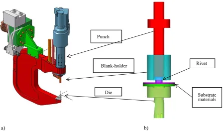
reproduce the geometry and shape of the SPR tooling. Figure 13a shows the geometry of the
real SPR C-frame while Figure 13b shows the virtual gun developed for the FE simulation. In
the latter, the entire C-frame shape has been replaced by three main rigid bodies which are
the punch, blank holder and die. Therefore, the only deformable bodies are the rivets and
substrate materials. The second step concerns the identification of the loads and motions
applied by the system. In general, depending on how the rivet is inserted, SPR systems are
classified in two categories: “punching” or “pushing”. In a punching system, the punch is
accelerated to a certain speed defined by the user and hits the rivet with an impact; while in a
pushing system, a gradually increasing force is applied to push the rivet into the workpiece
until it reaches a user defined displacement (Li et al., 2015).
The focus of this research was on the simulation of a pushing system. In this case, the process
is characterized by two main steps, first the substrate materials are clamped between the die
and blank-holder and then the punch pushes the rivet into the sheets until the rivet is sitting
31
The kinematic of the punch was simulated using constant velocity of 100mm/s while the
clamping force applied by the blank holder was modelled through a compressed spring with a
force of 5 kN which is representative of a typical SPR gun (Figure 14).
[image:32.595.88.539.233.496.2]
a) b)
Figure 13. a) Real C-frame b) Virtual C-frame Blank-holder
Die
Rivet
32
Figure 14. Schematic view of the axisymmetric model including the external loads applied
4.2 Mesh parameters
The mesh type and sizes represent an important aspect of the FEM as they affect both the
CPU time and accuracy of the simulation results. The element type used for the numerical
modelling was a 4-noded solid element (type 10) which is used for axisymmetric applications
(Marc, 2013a).
The definition of the mesh sizes was carried out through inverse analysis in order to assess
the optimum mesh dimensions which allow the lowest CPU time without affecting the
[image:33.595.213.380.78.296.2]accuracy of the results. Table 3 lists four different mesh sizes used for comparisons.
Table 3. Mesh sizes used for comparisons
Model No Rivet
[mm]
Top sheet
[mm]
Bottom sheet
[mm]
CPU time
1 0.05x0.05 0.1x0.1 0.1x0.1 37 min
2 0.05x0.05 0.1x0.1 0.15x0.15 31 min
3 0.07x0.07 0.15x0.15 0.2x0.2 14 min
33
a)
b)
[image:34.595.81.522.90.560.2]c) d)
Figure 15. Comparisons of different mesh sizes: a) Model 1, b) Models 2, c) Model 3, d) Model 4. Model 1 (a) and Model 4 (d) show interpenetration (circled) between elements of top and bottom sheets
Figure 15a and 15d show that models 1 and 4, which represent respectively the case of finer
and coarser mesh, reported element interpenetration (circled) between the top and bottom
sheet meshes. In these cases meshes of the same size were applied to the upper and lower
sheets. To avoid element interpenetration, the edge length of the rivet mesh was set
marginally finer compared to that of the top sheet. Similarly, between the top and bottom
sheet (model 2 and 3). This procedure is typical amongst finite element programmes. In
0.43 mm
0.62 mm
0.43 mm
34
Marc, the use of direct contact methods is possible to avoid penetration between bodies. This
method is based on the definition of touching-touched bodies which allows checking only for
nodes of the touching body and reduces the number of times that boundary nodes are used in
the creation of contact equations (Marc, 2013b). In this case, the contact directions were
assigned in order to treat the rivet as the touching body with respect to the top and bottom
sheets while the top sheet was treated as the touching body with respect to the bottom sheet.
In general finer mesh is used for the touching body and coarser mesh for touched body.
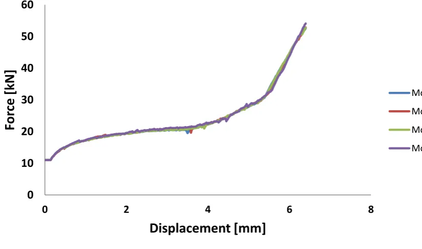
As shown by the cross-section of model 2 and 3 (Figure 15b and 15c) the application of this
method successfully avoided element interpenetration. Moreover, as the joint characteristics
and force vs displacement curves (Figure 16) showed similar results in both the models, the
mesh sizes used in this study were selected according to model 3 as it achieved a CPU time of
[image:35.595.84.497.348.592.2]14 minutes in comparison to the 31 minutes required for model 2.
Figure 16. Comparison of force vs displacement curves obtained with models 1, 2, 3 and 4
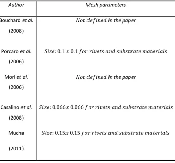
Table 4 lists the mesh parameters used by previous researchers on SPR simulation. The sizes
of the mesh used in this study are comparable with the literature, however, in this study
different mesh sizes were adopted for each deformable body, whilst other authors tend to use
the same mesh size for all the bodies. 0 10 20 30 40 50 60
0 2 4 6 8
35
Table 4: List of mesh parameters used in the literature for SPR simulation
Author Mesh parameters
Bouchard et al.
(2008)
𝑁𝑜𝑡 𝑑𝑒𝑓𝑖𝑛𝑒𝑑 in the paper
Porcaro et al.
(2006)
𝑆𝑖𝑧𝑒: 0.1 𝑥 0.1 𝑓𝑜𝑟 𝑟𝑖𝑣𝑒𝑡𝑠 𝑎𝑛𝑑 𝑠𝑢𝑏𝑠𝑡𝑟𝑎𝑡𝑒 𝑚𝑎𝑡𝑒𝑟𝑖𝑎𝑙𝑠
Mori et al.
(2006)
𝑁𝑜𝑡 𝑑𝑒𝑓𝑖𝑛𝑒𝑑 in the paper
Casalino et al.
(2008)
𝑆𝑖𝑧𝑒: 0.066𝑥 0.066 𝑓𝑜𝑟 𝑟𝑖𝑣𝑒𝑡𝑠 𝑎𝑛𝑑 𝑠𝑢𝑏𝑠𝑡𝑟𝑎𝑡𝑒 𝑚𝑎𝑡𝑒𝑟𝑖𝑎𝑙𝑠
Mucha
(2011)
𝑆𝑖𝑧𝑒: 0.15𝑥 0.15 𝑓𝑜𝑟 𝑟𝑖𝑣𝑒𝑡𝑠 𝑎𝑛𝑑 𝑠𝑢𝑏𝑠𝑡𝑟𝑎𝑡𝑒 𝑚𝑎𝑡𝑒𝑟𝑖𝑎𝑙𝑠
In order to deal with the large deformation of the mesh elements, automatic mesh refinements
were used. As shown in Figure 17, two re-meshing techniques available in
Simufact.formingTM were implemented: the Advancing front quad method that was used to re-mesh the elements of the substrate materials and the Quadtree method which was used to
36
Figure 17. Mesh refinement used for the numerical simulation of the SPR process
Finally, in order to allow the splitting of the top sheet during the rivet insertion, a geometric
failure criterion was applied. This method is based on an erosion technique which allows
elements of the mesh to be deleted when a user defined thickness value is reached. The
calibration of the user defined minimum element thickness was performed from inverse
analysis by comparing the force vs displacement curves of numerical and experimental tests.
The following three values were used for comparison: a) Tremoval = 0.02mm, b) Tremoval =
0.1mm and c) Tremoval = 0.2mm. Figure 18 shows the rivet insertion at time steps before and
after the erosion technique takes place for the three values of Tremoval.
Quadtree
37
a) b)
c) d)
[image:38.595.149.447.67.598.2]
e) f)
Figure 18. Rivet insertion at time steps before and after the erosion technique takes place: a) Tremoval = 0.02mm before erosion b) Tremoval = 0.02mm after erosion c) Tremoval = 0.1mm before erosion d) Tremoval = 0.1mm after erosion e) Tremoval = 0.2mm before erosion f) Tremoval = 0.2mm after erosion.
Figure 19 shows the comparisons between the experimental and numerical force vs
displacement curves for the three user defined values. It can be noticed that for Tremoval =
0.1mm and Tremoval = 0.2mm, a drop of force, as a consequence of the elements removal,
38
Figure 18f at the time step after the erosion technique has been applied, there are no elements
touching the rivet tip (circled). The user defined thickness value used for all the simulations
discussed in this study was Tremoval = 0.02mm as it achieved the best comparison with the
[image:39.595.88.511.162.396.2]experimental force vs displacement curve, as shown in Figure 19.
Figure 19. Comparisons of force vs displacement curves at Tremoval equal to 002mm, 0.1mm and 0.2mm
4.3 Coefficient of fiction
Another important aspect to take into account when modelling the SPR process is the friction
generated between the contact bodies. There are several interfaces where frictional contacts
occur: between the punch and rivet, between the substrate materials, between rivet and
substrate materials, between top sheet and blank-holder and between bottom sheet and die.
However, due to the difficulties in measuring the friction forces at these interfaces by in-situ
methods, the coefficients of friction are often determined via inverse methods.Therefore, the
coefficients of friction to assign into the FEM represent uncertain factors. As they affect the
simulation results, a robust calibration of the friction coefficients is required in order to allow
39
The friction model used in this study is based on the Coulomb law which describes the
relationship between the applied normal pressure and friction force through a linear equation:
𝜏 = 𝜇𝑃 (1)
Where 𝜏 is the friction shear stress, 𝑃 is the normal pressure and 𝜇 is the coefficient of friction.
The friction coefficients were determined from inverse analysis using one joint as reference
and successively validated with a series of different joints. Figure 20 shows the effect of the
friction coefficients on the numerical cross-section using two models as reference.
In Model 1, the following coefficient of friction were used: µ = 0.09 at the interface between
the sheets and between sheets and rivet, µ = 0.15 at the interface between the bottom sheet
and die, between top sheet and blank holder and between rivet and punch. In Model 2, a
friction coefficient of µ = 0.15 at the interface between the sheets and sheets and rivet, µ =
0.25 at the interface between the bottom sheet and die, between top sheet and blank holder
and between rivet and punch. It can be observed that Model 1 provided a better representation
of the experimental results (Figure 20a), whilst Model 2 showed lower flaring of the rivet
(Figure 20b).
Figure 20. comparison of cross-section geometries. a) model 1 - µ = 0.09 at the interface between the aluminum sheets and µ = 0.15 at the interface between the bottom sheet and die. b) model 2 - µ = 0.15 at the interface between the aluminum sheets and µ = 0.22 a
Figure 21 shows the comparison of the two models in terms of force vs displacement curves.
It can be noticed that Model 1 showed better agreement with the experimental curve which
indicates the validity of the selected friction coefficients. Therefore, based on these results,
the friction coefficients used in the FEM were defined according to Model 1 and were kept
40
Figure 21. Comparison between model 1 and 2. a) cross-section geometries b) force vs displacement curves
Table 5 lists the friction coefficients used in the literature for SPR simulation. It can be
observed that different researchers have used different friction coefficients, however the
values fall in the range between 0.1 to 0.3, which is representative of the friction coefficients
[image:41.595.122.476.438.763.2]used in this study.
Table 5: List of mesh parameters used in the literature for SPR simulation
Author Friction coefficient
Bouchard et
al. (2008)
𝝁 = 𝟎. 𝟏same for all the interfaces
Porcaro et al.
(2006)
𝝁 = 𝟎. 𝟏𝟓 between sheets
𝝁 = 𝟎. 𝟑 between blank holder and top sheet
𝝁 = 𝟎. 𝟑 between die and bottom sheet
Mori et al.
(2006)
𝝁 = 𝟎. 𝟐 same for all the interfaces
Casalino et al.
(2008)
𝝁 = 𝟎. 𝟏 same for all the interfaces
Mucha (2011) 𝝁 = 𝟎. 𝟎𝟓same for all the interfaces a)
41
5.
Discovery of the thermo-mechanical behaviour for SPR
simulation
Adiabatic heating due to localized plastic deformation and frictional contact has been
investigated in diverse areas such as ballistic impact, machining and high speed forming
processes (Rogers, 1979). The amount of heat generated by plastic deformation was first
studied by (Farron and Taylor, 1925) on steel, copper and aluminium. In all the cases, it was
found that about 90% of the plastic work was converted into heat while the remaining 10%
was stored in the material as internal energy. This is also valid for the dissipation of the
friction energy, where according to (Archard, 1959) nearly all the friction energy is dissipated
as heat.
The heat generated can either be dissipated to the surroundings or can determine a local
temperature rise of the material which can affect its mechanical behaviour. The latter is the
case of adiabatic heating where the rate of heat generation is greater than the rate of heat loss
(Kapoor, 1998). The effect of softening due to adiabatic heating is widely accepted and often
included in simulation of ballistic impact tests (Borvik et al., 2001) and friction welding processes (Awang et al., 2005).
SPR is essentially a cold forming operation where a rivet is inserted into a material stack in a
fraction of second. The process involves highly localized plastic deformation and friction
contacts which mainly affect the area surrounding the rivet legs and the area of the bottom
layer material filling the die cavity. In these conditions, both plastic deformation and friction
contact generate heating. Moreover, as the heat generated in the localised regions has no time
to transfer, it leads to adiabatic conditions.
The development of a reliable and accurate numerical model requires a detailed investigation
of the boundary conditions that affect the real process. One of the main challenges concerns
the development of an accurate material model which reflects the material response under the
specific process conditions. Therefore, a thermo-mechanical coupling finite element analysis,
which allows consideration of the dependency of the material properties upon the
temperature, might lead to a more precise prediction of the mechanical behaviour of the
materials.
In this chapter, an experimental procedure to measure the heat generated during the SPR
42
numerical analysis. Finally, the effect the of friction coefficient, punch velocity and thermal
conductivity on the temperature generated during the process have been investigated.
5.1 Experimental setup for temperature measurement during
SPR process
In the SPR process, plastic deformation and friction contact mainly occur in the area between
the rivet legs, therefore, the use of thermocouples to measure temperature changes might be
ineffective due to the high pressure and large amount of plastic deformation involved which
can damage the device. To overcome this issue, infrared thermography (IR) has been used in
this study to measure the temperature generated during the SPR process. IR camera devices
measure the infrared radiation emitted by an object and converts the energy detected into a
temperature value. The thermal-camera used in this study was the Flir IR SC5200 with a
resolution of 640x512 pixels.
The surface of the sample exposed to the thermal-camera was covered by a thin layer of matt
black paint which has emissivity of 0.9 (Holst, 2000) (Figure 22). Moreover, the area of the
SPR gun surrounding the samples to be riveted was also placed inside a box to avoid the
influence of the environment.
The temperature generated during the SPR process mainly affects the area surrounding the
rivet legs as this area is not visible, the riveting tests were only performed on a half portion in
order to expose the other half to the thermo-camera. This was achieved by placing the coupon
materials so they only covered half the die as shown in Figure 23a. The thermal-camera could
then be oriented to capture images of the visible half of the rivet during the insertion process.
Figure 23b shows the cross-section of the area visible to the thermal-camera for the
43
Figure 22: Thin layer of black paint applied on the lateral surface of SPR coupons
a) b)
Figure 23: Experimental procedures a) Coupons placed on the top of the die before riveting. b) Coupons with rivet inserted on half section
5.2 Experimental Results
During the experimental tests the following data were recorded:
Force vs displacement curves given by the SPR gun
Infrared images acquired at a frame rate of 500 fps (frames per seconds)
The experimental tests were performed using two layers of 2.5mm AC600 T4 aluminium
alloy as substrate material and boron steel rivets. As discussed in the previous section, only
44
friction contact involved in a typical SPR process were considered. Figure 24 shows the force
vs displacement curves obtained respectively from the full and half riveting process. It can be
noticed that the reaction force recorded in the case of the full joint was higher compared to
the half joint test with peak forces respectively 50kN and 37 kN. Therefore, it is expected that
the temperature measured represents only a fraction of the temperature generated during the
[image:45.595.73.503.207.465.2]full process.
Figure 24: Comparison of force vs displacement curves for full and half joints
The temperature profile measured with the thermal-camera is reported in Figure 25 and
shows a peak temperature of about 125 °C. Moreover, Figure 26a shows the images captured
by the thermal-camera at the frame number where the peak temperature was recorded. It was
observed that the temperature generated during the SPR process mainly affects the area
surrounding the tips of the rivet skirt. Figure 26b shows the area of the riveted sample where
the peak temperature occurs. 0
10 20 30 40 50 60
0 2 4 6 8 10
Fo
rc
e
[K
N
]
Disp. [mm]
Full joint