Original citation:
Liu, Haitao, Huang, Tian, Kecskeméthy, Andrés and Chetwynd, Derek G.. (2014) A
generalized approach for computing the transmission index of parallel mechanisms.
Mechanism and Machine Theory, 74 . pp. 245-256.
Permanent WRAP url:
http://wrap.warwick.ac.uk/78039
Copyright and reuse:
The Warwick Research Archive Portal (WRAP) makes this work by researchers of the
University of Warwick available open access under the following conditions. Copyright ©
and all moral rights to the version of the paper presented here belong to the individual
author(s) and/or other copyright owners. To the extent reasonable and practicable the
material made available in WRAP has been checked for eligibility before being made
available.
Copies of full items can be used for personal research or study, educational, or
not-for-profit purposes without prior permission or charge. Provided that the authors, title and
full bibliographic details are credited, a hyperlink and/or URL is given for the original
metadata page and the content is not changed in any way.
Publisher’s statement:
© 2014, Elsevier. Licensed under the Creative Commons
Attribution-NonCommercial-NoDerivatives 4.0 International http://creativecommons.org/licenses/by-nc-nd/4.0/
A note on versions:
The version presented here may differ from the published version or, version of record, if
you wish to cite this item you are advised to consult the publisher’s version. Please see
the ‘permanent WRAP url’ above for details on accessing the published version and note
that access may require a subscription.
A Generalized Approach for Computing the
Transmission Index of Parallel Mechanisms
Haitao Liu a, b, Tian Huang a, c, *, Andrés Kecskeméthy b, Derek G. Chetwynd c
a School of Mechanical Engineering, Tianjin University, Tianjin 300072, China
b Chair of Mechanics and Robotics, University of Duisburg-Essen, Duisburg 47057, Germany
c School of Engineering, The University of Warwick, Coventry CV4 7AL, UK
Abstract
This paper presents a novel approach for computing the transmission index of parallel mechanisms. The approach is based on an extended concept to compute the maximal virtual coefficient, which is an important notion involved in the formulation of dimensionally homogeneous transmission indices for singularity analysis and dimensional optimization of parallel mechanisms. By exploiting the dual property of the virtual coefficient, two characteristic points instead of one as in the current state of the art are defined: one characteristic point is located on the ‘floating’ axis of the transmission wrench, as in existing approaches, while a second one is located on the floating axis of the output twist of the platform, which is a novel concept. This allows one to define two characteristic lengths, of which the larger is then used for the measure of the “distance” between the transmission wrench screw and the output twist screw. As shown in this paper, this new measure makes it possible to discern more finely the configuration-dependent properties of kinematic performance of parallel mechanisms, thus making it more suitable for dimensional optimization. Confidence in this statement is demonstrated through the comparative study of two in-parallel mechanisms using the new method and previously existing ones.
Keywords: Virtual coefficient, transmission index, parallel mechanisms
1. Introduction
Finding suitably informative and sufficiently discernable performance indices is of crucial significance in the singularity analysis and dimensional optimization of parallel mechanisms having coupled translational and rotational movement capabilities. Although several performance indices have been proposed in the past using the algebraic characteristics of the Jacobian, these cannot be directly adopted for kinematic performance evaluation because the Jacobian varies with the scaling owing to the inconsistency in the physical units [1]. There are two ways to overcome this problem. The first one is to formulate a dimensionally homogeneous Jacobian in which all entries have the same physical units. The methods available for doing so include: (1) a length-based method, in which all translational elements in the Jacobian are normalized with the help of a “characteristic/natural length” [2-8]; however, this method depends on the choice of the characteristic length, and – although a “best” characteristic length can be defined by optimization notions [6] – the choice of an appropriate characteristic length and with this the combination of translational and rotational metrics for a particular operation is not unique; and (2) the point-based method, which makes use of linear maps between the joint rates and velocities of several points on the platform to overcome the problem of non-existence of a bi-invariant metric for combined rotation and translation [9-13]; however, defining good criteria for choosing proper points is an open issue needing investigation, as the locations of these points affect the algebraic characteristics of the Jacobian.
An alternative way to circumvent inhomogeneity of coordinates is to use the concept of the virtual coefficient [14] representing the virtual power delivered by a unit transmission wrench on the corresponding unit output twist of the target body. The virtual coefficient, closely related to the transmission/pressure angles of linkages [14-18], was originally introduced for evaluating the force transmission quality of single-loop linkages, i.e. the capability of a linkage to transmit a wrench via the motion-coupling joint of the output link. The virtual power delivered by the transmission wrench screw (TWS) on the output twist screw (OTS) was defined as the transmission factor (TF) [19]. Its normalized value, known as the transmission index (TI), was then defined in [20] by dividing the configuration-dependent value by the maximally attainable value when the transmission wrench screw is (virtually) rotated about a certain characteristic point, which in [20] was placed on the TWS axis at the point of intersection of the common normal of the TWS and the OTS. The thus defined TI has the merits of being invariant with regards to the coordinate frame of reference and dimensionally homogeneous in nature. However, problems can arise with this treatment, yielding undefined values, when the axes of the TWS and OTS are parallel. Moreover, the thus defined TI is configuration dependent, and thus lacks the notions of how the local value performs in comparison with the overall workspace. Thus, in [21] the concept of the TI was extended by specifying a new characteristic point on the axis of the TWS as the foot of the perpendicular to a “pressure centre” at the joint where the TWS is transmitted to the output link, and using as normalizing factor the maximum of all achievable maximal virtual coefficients obtained by rotating the TWS about the characteristic point at all configurations of the output link workspace. Unfortunately, this approach is suited solely for single-loop linkages in which the axis of the OTS is fixed on the ground. Recently, the concept of the virtual coefficient has been extended to deal with singularity identification and kinematic performance evaluation of parallel mechanisms [22-25]. In this setting, the input transmission index (ITI), the output transmission index (OTI), and the constraint transmission index (CTI) were defined for the assessment of the ‘closeness’ to different types of singularities of lower-mobility parallel manipulators throughout the entire workspace [25], showing that they are frame-independent and that they lie in a range [0, 1]. However, in these approaches only the orientation of the TWS is varied when determining the maximal virtual coefficient, and as shown in this paper the thus computed maximal virtual coefficients may fail to sense architectural or configuration variations, which again may lead to saddle points in some transmission indices that are detrimental when being used as cost functions in parallel mechanism dimensional optimization procedures.
OTS such that the maximal distance between them can be specified for all possible platform configurations and variations. Confidence in the correctness of this new approach is provided by two examples, comparing the results between the new and the previous methods, respectively.
2. Determination of maximal virtual coefficient
This section briefly reviews previous work on determining the maximal virtual coefficient in order to explore its application and limitations, respectively. Without loss of generality, consider a unit wrench
ˆ
w
$ known as the transmission wrench screw (TWS) and a unit twist ˆ$t
known as the output twist screw (OTS), as defined in [21]. The output twist screw ˆ$t is assumed to be the unit screw about which the output
link rotates instantaneously when inducing a small position variation. For the case of a single-loop mechanism this axis is fixed. The transmission wrench screw ˆ$w is the unit screw along which the transmitting link (mostly known as coupler in a single-loop mechanism, not shown in Fig. 1) transmits a wrench to the output link. For illustration purposes, the joints connecting the output link to the ground and to the transmitting link are shown in Fig. 1 as revolute joints, but any other joints can be used as well. The two screws can be expressed in the Plücker ray-coordinates and axial-coordinates, respectively, as
0
ˆ w w
w
w w w hw w
s s
s r s s
$ , ˆ t0 t t t t
t t t h
s r s s
s s
$ (1)
where sw (st) is the unit vector of the screw axis; hw (ht) is the pitch and rw (rt) the position vector of an arbitrary point on
the axis of ˆ$w ( ˆ$t). Then, the virtual coefficient can be defined by the inner product [21],
T
T T
ˆ ˆ cos sin
w t hthw s sw t rt rw stsw hthw θ d θ
$ $ (2)
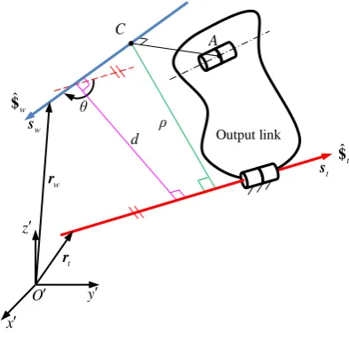
where d and are the distance and angle between the two screw axes (see Fig. 1). For single-loop spatial linkages, the maximal virtual coefficient was defined in [21] by (a) introducing an “application point” A located at the “centroid” of the joint connecting the output link with the wrench-transmitting link, and (b) determining the “characteristic point” C as that located on the axis of ˆ$w
closest to A. Then, the virtual coefficient can be rewritten as
2
T 2
WS max
ˆ ˆ max
w t hthw ρ
$ $ (3)
where ρ, known as the “characteristic length” (different than as defined in [2-8]), denotes the minimum distance from point C to the axis of ˆ$t. It can be seen that
T max
ˆ ˆ
w t
$ $ in Eq. (3) is a function of the maximal values of ht, hw, and ρ throughout the entire
workspace. However, for a parallel mechanism, since the axis of the output twist screw ˆ$t is unfixed and configuration dependent, it is infeasible to find these values because they vary with the shape, size, and location of the workspace. For this reason, a modified version of the maximal virtual coefficient was defined without proof in [25] as
2T 2
max max
ˆ ˆ
w t hthw d
$ $ (4)
where dmax represents the maximal length of the common normal of the axes of ˆ$w and ˆ$t when the screw axis of ˆ$w is rotated about the application point. Here, the application point was not defined unambiguously, although the authors stated it was more or less the same as the characteristic length proposed by Chen and Angeles [21].
At this point, it can be verified that the dual property of the virtual coefficient as expressed in Eq. (2) makes it possible to define
two characteristic points, located respectively on the axes of ˆ$w and ˆ$t, about which either the transmission wrench screw axis or
the output twist screw axis can be rotated, respectively. This gives rise to a new sense of determining the characteristic length ρ and the maximal distance dmax, in which the corresponding quantities defined in [21, 25] are just a special case. This is derived and illustrated by examples in the sequel.
3. Determination of the maximal virtual coefficent for a given configuration
Addressing the problems mentioned above, this section presents an expression for the maximal virtual coefficient and derives explicit expressions for the orientation of the screw axes and the characteristic lengths at the maximally achievable values of the virtual coefficient for application to parallel mechanisms. The presented approach is valid for parallel mechanisms, in which the last joint of a limb connecting the platform can be decomposed as 1-DOF revolute or prismatic joint.
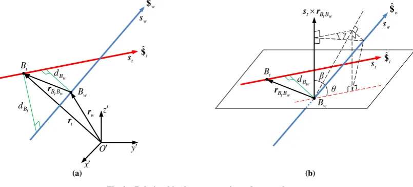
Let a general wrench screw ˆ$w and a general twist screw ˆ$t be given, and let two arbitrary points Bw and Bt be chosen on the wrench and twist axes ˆ$w and ˆ$t, respectively (Fig. 2(a)). Application of Eq. (2) and cyclic permutation of the vectors involved
[image:3.595.341.536.55.242.2]in the triple scalar product allows one to obtain two equivalent expressions for the virtual coefficient:
T T T
ˆ ˆ
t w w t hthw s sw tsw strB B
$ $ (5a)
T T T
ˆ ˆ
w t w t hthw s sw t st swrB B
$ $ (5b)
where
t w w t
B B B B t w
r r r r . Each of these expressions gives rise to a different geometrical interpretation of the computation of the maximal virtual coefficient, as explained below. For simplicity, we initially consider only Eq. (5a); a similar result can be derived from Eq. (5b) by a similar rationale. If
w t w
B t B B
d s r denotes the orthogonal distance from point Bw on the axis of ˆ$w to the
axis of ˆ$t, Eq. (5a) can be rewritten as
T
ˆ ˆ cos cos
w w t hthw θ dB β
$ $ (6) where is the angle between sw and
t w t B B
s r as shown in Fig. 2(b). According to the law of cosines,
cos θ cos γ sin β (7) where γ is the dihedral angle. Substituting Eq. (7) into Eq. (6) yields
T
ˆ ˆ cos sin cos
w
w t hthw γ β dB β
$ $ (8)
If one allows the wrench axis ˆ$w to rotate freely about point Bw, it is easy to prove that ˆ ˆT
w t
$ $ associated with
w B
d takes the maximal value
2T 2
max
ˆ ˆ w +
w B
w t hthw dB
$ $ (9)
when
0
w B
γ , π arctan 2 w w B B t w d β h h (10)
Obviously, its counterpart associated with Eq. (5b) can be obtained by allowing now the twist screw ˆ$t to rotate freely about point
t
B . Hence, using
t w t
B w B B
d s r as the orthogonal distance from point Bt on the axis of ˆ$t to the axis of ˆ$w, the maximal
virtual coefficient associated with rotational variations of the twist screw ˆ$t about point Bt is given by
2T 2
max
ˆ ˆ t +
t B
w t hthw dB
$ $ (11) when
0
t B
γ , π arctan 2 t t B B t w d β h h (12)
As both previous variations are conceivable for the determination of the maximal virtual coefficient, the overall maximal virtual Fig. 2 Relationships between a twist and a wrench
(b) w B t B w B d t w t B B
[image:4.595.96.499.62.244.2]coefficient, as proposed in this paper, must be determined by the maximum of the two:
T T T
max max max
ˆ ˆ max ˆ ˆ Bw , ˆ ˆ Bt
w t w t w t
$ $ $ $ $ $ (13)
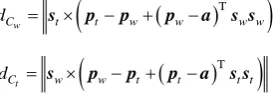
Note that in the previous definition, the individual maximal virtual coefficients depend on the choice of points Bw and Bt located on the general wrench and twist screws, respectively. For parallel mechanisms, these points should be selected such that they characterize the effects of the corresponding transmission wrench and output twist screws at the boundary between the leg and the platform. Thus for this case they are termed “the transmission characteristic point and the output characteristic point” and are denoted by Cw and Ct, respectively. We define the characteristic points Cw and Ct according to Chen and Angeles [21] as the points on
the screw axes ˆ$w and ˆ$t, respectively, that are closest to the so-called “centroid” A of the joint connecting the corresponding limb with the platform. The centroid can be interpreted here as the center of the embodiment of the joint, which is unique for the case of spherical joints but depends on the manufacturing form for revolute or prismatic joints (Fig. 3). By choosing orthogonal radius vectors pw and pt from the (moving) platform reference origin O to arbitrary points Pw and Pt on the wrench and twist screw axes ˆ$w and ˆ$t, respectively, explicit expressions for
t C d and
w C
d termed “the transmission characteristic length and the output characteristic length” can be obtained as
T
w
C t t w w w w
d s p p p a s s (14a)
T
t
C w w t t t t
d s p p p a s s (14b)
where pwswsw0 and pt st st0, and a is the position vector from the (moving) platform reference origin O to the
application point A of the actual leg. These considerations enable the maximal virtual coefficient to be finally determined by
2T 2
max max
ˆ ˆ +
w t hthw d
$ $ , max max
,
w t
C C
d d d (15)
It should be pointed out that if the pitch of either ˆ$w or ˆ$t is infinite, then all terms in Eq. (15) apart from the infinite pitch can be
neglected and thus one obtains [20, 21]:
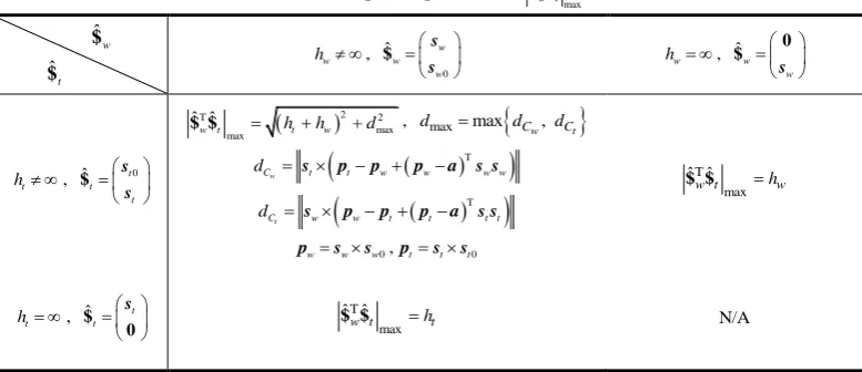
Table 1 Explicit expressions of T max
ˆ ˆ w t $ $
$ˆw
$ˆt
w
h ,
0 ˆ w w w s s
$ hw , ˆw
w
s
0 $
t
h , ˆt t0 t s s $
2T 2
max max
ˆ ˆ +
w t hthw d
$ $ , dmaxmax
dCw, dCt
T
w
C t t w w w w
d s p p p a s s
T
t
C w w t t t t
d s p p p a s s
0
w w w
p s s ,pt st st0
T max ˆ ˆ
w t hw
$ $
t
h , ˆ t t s $ 0 T max ˆ ˆ
w t ht
$ $ N/A
Fig. 3 Two possible definitions of characteristic points
Platform A x y z O a ˆ t
$ $ˆw
w C w C d w P w p t p t P (b) (a) Platform A x y z O a ˆ t
$ $ˆw
[image:5.595.101.497.50.434.2] [image:5.595.220.357.634.681.2](1) if ht is infinite, then
T max
ˆ ˆ
w t ht
$ $ ;
(2) if hw is infinite, then
T max
ˆ ˆ
w t hw
$ $ ;
[image:6.595.175.518.234.315.2](3) the case that both pitches are infinite does not exist for the transmission wrench and the output twist [21]. Table 1 summarises the explicit expressions for T
max
ˆ ˆ
w t
$ $ for all possible cases.
4. Performance indices formulation using the virtual coefficient
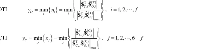
We apply the above derived expression of the maximal virtual coefficient to compute the output and constraint transmission indices, respectively developed in [21, 25]. In order to illustrate the concepts, the derivations are made for f-DOF ( f6) non-overconstrained and non-redundant in-parallel mechanisms composed of f limbs having exactly one actuator each. For such parallel mechanisms, the local transmission indices, i.e. the output transmission index (OTI) and the constraint transmission index (CTI) [25] are considered since the kinematic performance in the directions of theoretically accessible and inaccessible instantaneous motions must be evaluated at the same time. The thus introduced output and constraint transmission indices are defined, respectively, as
OTI
T T , , T T , , max ˆ ˆ min min ˆ ˆ
T i O i
O i i i
T i O i
γ η $ $ $ $
, i1, 2, ,f (16)
CTI
C T , , C T , , max ˆ ˆ min min ˆ ˆ
C j O j
C j j j
C j O j
γ ε $ $ $ $
, j1, 2, ,6f (17)
Utilizing the terminology and notation given in [25], $ˆT i, is referred to as the thi transmission wrench screw (TWS), which is produced at the boundary of the leg with the platform by the ith actuated joint, while $ˆC j, is referred to as the jth constraint
wrench (CWS) , which is produced by the jth remaining locked spatial directions at one of the legs when the actuator joints of all legs are released. Note that the number of TWS and CWS always sums up to 6 for the case of a non-overconstrained platform. Along the same lines, $ˆ O iT, is referred to as the thi output twist screw, produced by locking all actuated joints but the ith one, and recording
small platform pose variations, while $ˆ O jC, is referred to as the jth constraint twist screw, which is produced by locking all actuated
joints and releasing one characteristic constraint direction along a virtual constraint joint, and observing again the variations of pose of the platform. Here, the term ‘virtual constraint joint’ represents a fictitious joint that is added to a leg in one-to-one correspondence to a CWS, which is normally fixed due to rigidity but which can be “released” for conceptual reasons. A virtual constraint joint can actually generate small motions in a platform due to elasticity and/or clearance effects; the set of virtual constraint joints can then be regarded as representing the minimal system of characteristic small perturbations due to elasticity and/or clearance. Note again that the number of joint twist screws and constraint twist screws sum up to 6 for the case of non-overconstrained platforms. By the dual and reciprocal properties of the screw system of a limb, a TWS is reciprocal to all joint twists but the actuated one in the corresponding limb, while a CWS is reciprocal to all joint twists, including the passive and actuated ones in the corresponding limb [26]. They thereby can be formulated by means of the observation method [27]. Note that as thus $ˆT i, ($ˆC j, ) only exerts power on
(T ) ,
ˆ
O i $ ( (C)
,
ˆ
O j
$ ), then given $ˆT i, and $ˆC j, , (T )
,
ˆ
O i
$ and (C) ,
ˆ
O j
$ can uniquely be determined by two steps (1) Solve a set of linear equations forB
T
B A (18)
where
,1 , ,1 ,6
ˆ ˆ ˆ ˆ
T T f C C f
A $ $ $ $ , (T) (T) (C) (C)
,1 , ,1 ,6
O O f O O f
B $ $ $ $
(2) Determine (T) (T) (C) (C)
,1 , ,1 ,6
ˆ ˆ ˆ ˆ
O O f O O f
B $ $ $ $ by normalizing each column vectors of B with its magnitude such that
(T) (T)
, (T) ,
1 ˆ
O i O i
i λ
$ $ , (C) (C)
, (C) ,
1 ˆ
O j O j
j λ
$ $ , i1, 2, ,f , j1,2, ,6f (19)
Consequently, a parallel mechanism is said to be at an output transmission singularity if (T) T T , ,
ˆ ˆ 0
i T i O i
λ $ $ , and at a constraint singularity if (C) T C
, ,
ˆ ˆ 0
j C j O j
λ $ $ . Therefore, larger values of transmission indices given in Eqs. (16) and (17) indicate better corresponding kinematic performance.
where the platform will move even if all actuated joints are locked).
In what follows we will use the indices normalized by our new maximal virtual coefficient to evaluate kinematic performance of two in-parallel mechanisms, and the results will be compared with those obtained by other methods.
5. Computation of output and constraint transmission indices for a 3-SPR parallel mechanism
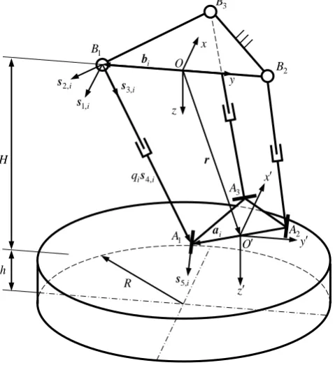
The first example under consideration is a 3-SPR in-parallel mechanism composed of a base, a platform and three identical SPR limbs (Fig. 4). Here, R and S represent a revolute and spherical
joint, respectively, and the underlined P denotes a prismatic joint driven by a servomotor. A fixed reference frame Oxyz
is placed on the base with O being at the centre of B B1 2 such that the xy plane contains the triangle ΔB B B1 2 3 with the y axis parallel to B B1 2 . A moving reference frame
Ox y z in which all screws are evaluated is also set to have
O coincident with the centre of A A1 2 while keeping its three orthogonal axes parallel to those of Oxyz. Here, Bi is the center of the spherical joint; Ai is the intersecting point of the axis of the prismatic joint with the axial axis of the revolute joint.
For illustration purposes, the transmission indices are evaluated within a cylindrical task workspace, with H being the distance from the top plane to ΔB B B1 2 3, R being the radius, and h being the height of the workspace as shown in Fig. 4. However, similar qualitative properties as the ones shown here apply also when the evaluated positions are in the neighbourhood of the reachable workspace boundaries, as will be shown in the second example. As the focus of this paper is on the proposition and verification of a new TI measurement, determining the reachable workspace for general parallel manipulators is outside of the scope of this paper.
The centroids Ai ( i1, 2,3 ) are chosen as the intersections of the leg axes with the revolute joint axes on the platform, respectively. The TWS and CWS can be formulated by 4, , 4, ˆ i T i i i s a s
$ , ,
5,
4, 5,
ˆ i
C i
i qi i i
s
a s s
$ , i1, 2,3 (20)
where ai is the position vector of Ai; qi is the thi limb length; s4,i is the unit vector of the actuated prismatic joint and s5,i
is the unit vector of the revolute joint connecting the thi limb with the platform, satisfying s4,is5,i, s5,1 a3, s5,2 a3, and
5,3 A A1 2
s . This allows $ˆ O iT, and $ˆ O iC, to be computed by the procedure given in Section 4.
For realistic parameters, we set a1 a2 75 mm, a3 150 mm, b1 b2 250 mm, b3 500 mm, H750 mm, 800 mm
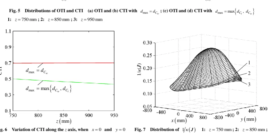
R , and h200 mm. Fig. 5(a)-(d) show how the OTI and the CTI vary within the top, middle, and bottom layers of the cylindrical task workspace. Fig. 5(a) and (c) show the OTI determined by max
w C
d d and by max max
,
w t
C C
d d d , respectively; it turns out that they are numerically the same. This means that dmax is dominated by
w B
d regardless of the system configurations. In contrast, the CTI defined by max
w C
d d is completely different from that defined by max max
,
w t
C C
d d d , as shown in Fig. 5(b) and (d), respectively. In fact, as can be seen from the non-overlapping level sets of Figs. 5(b) and 5(d), in the case of the CTI actually dmax is now dominated, for this particular platform, by dCt and it holds dmax dCt everywhere regardless of the
confirmation. In particular, one can see that the CTI using the existing approach with max
w C
d d displays a saddle, making its use for optimization purposes impractical. On the other side, by using the here proposed maximal virtual coefficient
max max Cw, Ct
d d d , a positive definite behaviour is noticeable in the neighbourhood of the maximum, which makes of the use of the CTI as cost function for optimization tasks a well-posed problem. The underlying behaviour can be seen from Fig. 6, which shows the variation of the CTI along the z axis (x0 and y0). Clearly, CTI defined by max
w C
d d remains nearly constant at a value of 0.7, while the CTI defined by the present approach as max max
,
w t
C C
d d d linearly decreases as the z coordinate increases. Moreover, there is no intersection between the two lines, showing that
t C
d is always larger than
w C
d . This also indicates that, while the previously published CTI is everywhere insensitive to platform configuration, the newly presented CTI shows a clear dependency on platform position, making it suitable to optimize platform position with respect to the CTI.
In order to compare the performance index developed here, we compare our results with a “conventional” performance index Fig. 4 Schematic diagram of a 3-SPR mechanism
[image:7.595.301.541.140.402.2]computation using the condition number. In order to be able to compute the condition number, we have to find a Jacobian that is homogeneous in the chosen coordinates. We can achieve this in this particular case by choosing the three coordinates of the position vector r
x y z
T of the platform center as generalized coordinates. Then, the 3x3 Jacobian can be formulated as
Jr q, JJvvJ Jvω ωω ωv1J (21) where
Fig. 6 Variation of CTI along the z axis, when x0 and y0
mm
z
CTI dmaxdCw
max max Cw, Ct
d d d
Fig. 7 Distribution of 1κ
J 1: z750 mm; 2: z850 mm;3: z950 mm
mm
x y
mm
1/
κ
(
J
) 1
2 3 (a) (b)
mm
y
mm
x
OTI
mm
y
mm
x
C
TI
3 2 1
1 2 3
Fig. 5 Distributions of OTI and CTI (a) OTI and (b) CTI with dmaxdCw; (c) OTI and (d) CTI with dmaxmax
dCt,dCw
1: z750 mm; 2: z850 mm; 3: z950 mm
(c) (d)
mm
y
mm
x
OTI
mm
y
mm
x
C
TI
1 2 3 1
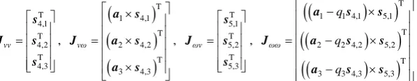
[image:8.595.60.542.66.429.2] [image:8.595.68.534.425.660.2]T 4,1 T 4,2 T 4,3 vv s J s s ,
T 1 4,1 T 2 4,2 T 3 4,3 vω a sJ a s
a s , T 5,1 T 5,2 T 5,3 ωv s J s s ,
T 1 1 4,1 5,1T 2 2 4,2 5,2
T 3 3 4,3 5,3
ωω q q q
a s s
J a s s
a s s
and r is the vector connecting the base origin O to the platform origin O. As the Jacobian J is now dimensionally homogeneous, it can be computed using the procedure described in [13]. Because J fully contains the transmission and constraint wrench screws simultaneously as seen in Eq. (21), it is reasonable to expect that the distributions of OTI and CTI as separate measures are consistent with that of the inverse of the condition number of J. As shown in Fig. 7, the inverse of the condition number of J, 1κ
J , throughout the task workspace has a shape and variation of magnitude along the z axis that match well those of the OTI and the CTI computed by dmaxmax
dCw, dCt
, but inconsistent with that of the CTI computed by dCw. This shows that the newly proposedtransmission indices agree well with the “classical” performance index employing the inverse of the condition number when the Jacobian is dimensionally homogeneous, which is not the case for the previously defined transmission indices. In this setting, it should be noted that the application of the present method to a platform with homogenizable Jacobian has been performed here for comparison purposes only. By using other generalized coordinates, the Jacobian would not have been homogeneous and the condition number would not be a sensible measure. However, as the present approach does not depend on dimensionally homogeneous Jacobians, it can be applied also to cases where the parallel mechanism has coupled translational and rotational movement capabilities and/or the choice of generalized coordinates does not render a dimensionally homogeneous Jacobian. Such a case is shown in the next example, where a 3-RPS parallel mechanism is treated.
6. Computation of output and constraint transmission indices for a 3-RPS parallel mechanism
[image:9.595.150.449.60.118.2]Using the same performance indices OTI and CTI, a 3-RPS in-parallel mechanism with coupled translational and rotational movement capabilities is investigated in this section to further show the consistency of the proposed approach with the method using the condition number of an equivalent dimensionally homogeneous Jacobian based on the point-based method.
Fig. 8 shows the schematic diagram of the mechanism composed of a base, a platform and three identical RPS limbs. A fixed reference frame Oxyz is placed on the base with O being at the centre of the equilateral triangle
1 2 3
ΔB B B such that the xy plane contains the triangle, with the x axis parallel to B B1 2. An moving reference frame Ox y z in which all screws are evaluated is also set to have O coincident with the centre of the equilateral triangle ΔA A A1 2 3 while keeping its three orthogonal axes parallel to those of Oxyz. Here, Ai is the center of the spherical joint; Bi is the intersecting point of the axis of the prismatic joint with the axial axis of the revolute joint.
It is well known that the 3-RPS parallel manipulator has two rotational and one translational degrees of freedom. Its orientation matrix of the platform with respect to the base can be obtained using three Euler angles, ψ, θ and in terms of precession, nutation, and body rotation according to the z-x-z
convention, and the relationship ψ holds for ψ and [13]. Its kinematic performance can be investigated in the orientation workspace with
ψ and θ for fixed z coordinate. The centroids Ai (i1, 2,3) are chosen as the intersections of the leg axes with the revolute joint axes on the platform, respectively. The TWS and CWS can be formulated by
2, , 2, ˆ i T i i i s a s
$ , , 1,
1, ˆ i C i i i s a s
$ , i1, 2,3 (22)
where ai is the position vector of Ai; s2,i is the unit vector of the actuated prismatic joint and s1,i is the unit vector of the
revolute joint connecting the ith limb with the base, satisfying s1,is2,i. This allows
T
,
ˆ
O i
$ and$ˆ O iC, , to be computed by the
procedure given in Section 4. Then, given a set of geometric parameters ai 250 mm and bi 312.5 mm, the distributions of OTI and CTI in the orientation workspace of the mechanism are shown in Fig. 9 given z=536.4 mm to z=736.4 mm.It can be seen from Fig. 9(a) that the values of the OTI take the maximum when θ0 and decrease monotonically with the increase of θ, and approach to zero at θ55.13 for z=536.4 and ψ60 , 180 , and 300 . Meanwhile, the values of the CTI also approach zero at the transmission singular configurations as shown in Fig. 9(b) though they remain almost constant elsewhere.Moreover, the values of the OTI increase as the z coordinate increases, meaning that the kinematic performance can be improved slightly by increasing the distance between O and O within the given range of the stroke. The computational results show that
max max Cw, Ct Cw
d d d d for both OTI and CTI in this particular problem, thus for this case the newly presented TI coincides Fig. 8 Schematic diagram of a 3-RPS mechanism
O
1B bi
3 B 2 B x y 1,i s z r 2, i i qs 3,i s 4,i s 5,i
s x
[image:9.595.357.535.322.558.2]with the existing one in [25]. As a comparison study, Fig. 10 shows the distribution of the inverse of the condition number of J,
1κ J , in the orientation workspace, where J is the dimensionally homogeneous Jacobian derived using the point-based method [13]. It can be seen that the OTI has a shape and variation of magnitude along the z axis that match well those of 1κ
J . Again, this coincidence shows that the proposed TI is a good performance index which for the case of homogeneous Jacobians reproduces well the “classical” performance indices, thus supporting it general relevance. It should be noted however that by the new approach the equivalent performance indices can be determined without any need to “homogenize” the Jacobian, which requires the choice of measurement points.7. Conclusions
This paper presents a new procedure to determine the maximal virtual coefficient and by this a new generalized approach for computing the transmission index of parallel mechanisms. In this setting, the following conclusions can be drawn:
(1) The characteristic length defined in previous papers for single-loop linkages having a fixed axis for the output twist screw (OTS) can be generalized for parallel mechanisms.
(2) Utilizing the dual property of the virtual coefficient, two characteristic points Cw and Ct on the axes of the transmission
wrench screw (TWS) and output transmission screw (OTS) can be defined, respectively, about which the corresponding screw axes may be virtually rotated for finding the maximal value of the characteristic length. This leads to two characteristic lengths dCw and
t C
d between the TWS and the OTS from which the maximum dmaxmax
dCw, dCt
can be used for computing the maximalvirtual coefficient.
(3) The newly introduced maximal virtual coefficient provides a new approach for computing the output and constraint transmission indices, OTI and CTI, respectively, which as shown by the example of a 3-SPR, is more sensitive to platform configuration for the CTI than the existing method and thus is better suited for platform configuration optimization.
(4) An analysis of the two examples 3-SPR and 3-RPS parallel mechanisms shows that for the case of dimensionally homogenizable Jacobians, the transmission index proposed in this paper behaves similar to the inverse of the condition number of dimensionally homogeneous Jacobians. In particular, a comparison of the new TI approach with the existing one shows for the example of the 3-SPR that the CTI displays a convex behaviour in the neighbourhood of the maximum, while the previous TI approach yields a saddle point. This makes the approach interesting for generating well-posed cost function in kinematic performance optimization of lower-mobility parallel mechanisms.
(5) While the approach presented in this paper yields similar behaviour as the classical condition number kinematic performance measure, it has the advantage that no “homogenization” steps for the Jacobian are required such as selection of points for point-based Jacobians or the introduction of a characteristic length. Instead, using the proposed OTI and CTI allows one to assess kinematic performance in terms of transmission and constraint in a separate manner.
Acknowledgments
This research is partially supported by the National Natural Science Foundation of China (NSFC) under Grant 51135008, ECROBOT under Grant FP7-PEOPLE-2012-IRSES (318971), and the Alexander von Humboldt (AvH) Foundation of Germany.
Fig. 10 Distributions of 1κ
J xcos, θyθsinψ1: z536.4 mm; 2: z636.4 mm; 3: z736.4 mm
y
θ
x
θ
1/
κ
(
J
)
1 2 3 Fig. 9 Distributions of (a) OTI and (b) CTI with dmaxmax
dCt,dCw
xcos, θyθsinψ 1: z536.4 mm;2: z636.4 mm; 3: z736.4 mm
y
θ
x
θ
OTI
1 2 3
y
θ
x
θ
C
TI
1 2 3
[image:10.595.62.539.67.243.2] [image:10.595.310.536.281.442.2]References
[1] J.-P. Merlet, Jacobian, manipulability, condition number, and accuracy of parallel robots, ASME Mech. Des., 128(1): 199–206, 2006.
[2] O. Ma, J. Angeles, Optimum architecture design of platform manipulators, in Proc. 5th Int. Conf. Adv. Robot., 2: 1130–1135, 1991.
[3] M. Tandirci, J. Angeles, F. Ranjbaran, Characteristic point and the characteristic length of robotic manipulators, ASME Des. Eng. Division, 45: 203–208, 1992.
[4] J. Angeles, F. Ranjbaran, R. V. Patel, On the design of the kinematic structure of seven-axes redundant manipulators for maximum conditioning, in Proc. IEEE Int. Conf. Robot. Autom., Nice, France, May 10–15, 494–499, 1992.
[5] J. Angeles, Kinematic isotropy in humans and machines, in Proc. IFToMM 9th World Congr. Theory Mach. Mech., Milan, Italy, Aug. 29–Sep. 2, 1: XLII–XLIX, 1995.
[6] J. Angeles, Is there a characteristic length of a rigid-body displacement?, Mech. Mach. Theory, 41(8): 884–896, 2006.
[7] W. A. Khan, J. Angeles, The kinetostatic optimization of robotic manipulators: The inverse and the direct problems, ASME J. Mech. Des., 128(1): 168–178, 2006.
[8] J. Angeles, Fundamentals of Robotic Mechanical Systems: Theory, Methods, and Algorithms, 3rd ed. New York: Springer-Verlag, 2003.
[9] S.-G. Kim, J. Ryu, New dimensionally homogeneous Jacobian matrix formulation by three end-effector points for optimal design of parallel manipulators, IEEE Trans. Robot. Autom., 19(4): 731–736, 2003.
[10] O. Altuzarra, O. Salgado, V. Petuya, A. Hernández, Point-based Jacobian formulation for computational kinematics of manipulators, Mech. Mach. Theory, 41(12): 1407–1423, 2006.
[11] G. Pond, J. A. Carretero, Formulating Jacobian matrices for the dexterity analysis of parallel manipulators, Mech. Mach. Theory, 41(12): 1505–1519, 2006.
[12] G. Pond, J. A. Carretero, Quantitative dexterous workspace comparison of parallel manipulators, Mech. Mach. Theory, 42(10): 1388–1400, 2007.
[13] H. Liu, T. Huang, D. G. Chetwynd, A method to formulate a dimensionally homogeneous Jacobian of parallel manipulators, IEEE Tran. Robot., 27(1): 150–156, 2011.
[14] R. S. Ball, A Treatise on the Theory of Screws, Cambridge University Press, 1900.
[15] H. Alt, Der Übertragungswinkel und seine Bedeutung für das Konstruieren periodischer Getriebe, Werkstattstechnik 26: 61–64, 1932.
[16] K. Hain, Applied Kinematics, McGraw-Hill, 1967.
[17] T. L. Dresner, K. W. Buffinton, Definition of pressure and transmission angles applicable to multi-input mechanisms, ASME J. Mech. Des., 113: 495–499, 1991.
[18] S. Bawab, G. L. Kinzel, K. J. Waldron, Rectified synthesis of six-bar mechanisms with well-defined transmission angles for four position motion generation, ASME J. Mech. Des., 118: 377–383, 1996.
[19] M. S. C. Yuan, F. Freudenstwin, L. S. Woo, Kinematic analysis of spatial mechanism by means of screw coordinates. Part 2 – Analysis of spatial mechanisms, ASME J. Eng. Industry, Series B 91(1): 67–73, 1971.
[20] G. Sutherland, B. Roth, A transmission index for spatial mechanisms, ASME J. Eng. Industry (May), 589–597, 1973.
[21] C. Chen, J. Angeles, Generalized transmission index and transmission quality for spatial linkages, Mech. Mach. Theory, 42(9): 1225–1237, 2007.
[22] Y. Takeda, H. Funabashi, A transmission index for in-parallel wire-driven mechanisms, JSME Series C, 44(1): 180–187, 2001. [23] C. C. Lin, W. T. Chang, J. J. Lee, Force transmissibility performance of parallel manipulators, J. Robot. Syst., 20: 659–670,
2003.
[24] J.-S. Wang, C. Wu, X. Liu, Performance evaluation of parallel manipulators: motion/force transmissibility and its index, Mech. Mach. Theory, 45(10): 1462–1476, 2010.
[25] X.-J. Liu, C. Wu, J.-S. Wang, A new approach for singularity analysis and closeness measurement to singularities of parallel manipulators, ASME J. Mech. Robot., 4(4): 041001(10 pages), 2012.
Listing of figure captions:
Fig. 1 The characteristic length defined in [21] Fig. 2 Relationship between a twist and a wrench Fig. 3 Definitions of two characteristic points Fig. 4 Schematic diagram of a 3-SPR mechanism
Fig. 5 Distributions of OTI and CTI (a) OTI and (b) CTI with max
w C
d d ; (c) OTI and (d) CTI with max max
,
t w
C C
d d d 1: z750 mm; 2:
850 mm
z ; 3: z950 mm
Fig. 6 Variation of CTI along the z axis, when x0 and y0
Fig. 7 Distribution of 1κ
J 1: z750 mm; 2: z850 mm; 3: z950 mmFig. 8 Schematic diagram of a 3-RPS mechanism
Fig. 9 Distributions of (a) OTI and (b) CTI with max max
,
t w
C C
d d d xc o s, θyθsinψ 1: z536.4 mm; 2: z636.4 mm; 3:
736.4 mm
z
Table 1 Explicit expressions of T max
ˆ ˆ w t $ $
$ˆw
$ˆt w
h ,
0
ˆ w
w w
s s
$ hw , ˆw
w
s
0 $
t
h , ˆ t0
t t
s s
$
2T 2
max max
ˆ ˆ +
w t hthw d
$ $ , dmaxmax
dCw, dCt
T
w
C t t w w w w
d s p p p a s s
T
t
C w w t t t t
d s p p p a s s
0
w w w
p s s ,pt st st0
T max ˆ ˆ
w t hw $ $
t
h , ˆ t t
s
$ 0
T max ˆ ˆ
w t ht
[image:13.595.104.493.69.237.2]Figure 1
Output link
A
θ
d
ˆ
w $
C
w
s ρ
ˆ
t $ t
s
t
r
x
y z
O w
Figure 2
(b)
w B t
B
w B d
t w t B B
s r
ˆ
t $ t
s
ˆ
w $
w
s
θ β
γ
(a)
t w B B
r
t
r
x
y z
O w
r
w B t
B
w B d
ˆ
t $ t
s
ˆ
w $
w
s
t w B B
r
Figure 3
Platform
A
x
y z
O
a
ˆ
t
$ $ˆw
w C w C d
w P
w
p
t
p
t P
(b) (a)
Platform
A
x
y z
O
a
ˆ
t
$ $ˆw
t C
t C d
w P
w
p
t
p
Figure 4
O x
y
z
O
3
B
3
A
2
A
1
A
2
B
1
B
r
i
a
4,
i i qs
1,i
s
2,i
s
3,i
s
5,i
s
i
b
x
y
z h
(a) (b)
mm
y
mm
x
OTI
mm
y
mm
x
C
TI
3 2 1
1 2 3
Figure 5
(c) (d)
mm
y
mm
x
OTI
mm
y
mm
x
C
TI
1 2 3 1
[image:18.595.66.540.82.451.2]Figure 6
mm
z
CTI dmaxdCw
max max Cw, Ct
[image:19.595.186.397.65.246.2]Figure 7
mm
x y
mm
1/
κ
(
J
) 1
Figure 8
O
1B bi
3
B
2
B
x y
1,i
s
z
r
2,
i i
qs
3,i
s
4,i
s
5,i
s x
y z
1
A
2
A
3
A O i
Figure 9
y
θ
x
θ
OTI
1 2 3
y
θ
x
θ
C
TI
1 2 3
Figure 10
y
θ
x
θ
1/
κ
(
J
)
![Fig. 1 The characteristic length defined in [21]](https://thumb-us.123doks.com/thumbv2/123dok_us/9542930.459180/3.595.341.536.55.242/fig-characteristic-length-defined.webp)