Abstract—The paper presents the concept of a new engine called variable volume engine. The volume of variable volume engine is not constant. In the variable volume four stroke engines, during the two strokes there will be one volume and during the other two strokes, there will be another volume. The main aim of this engine is to achieve a combined advantage of the variable compression ratio and supercharging. It is observed that overall efficiency of the engine also increases. Thus variable volume engine has the advantage of the increased volumetric efficiency due to supercharging and the increased efficiency of the engine due to both supercharging and variable compression ratio. Otto and diesel cycles are drawn and the performance of variable volume engine is compared with the supercharged engine and their simulated graphs are drawn.
Keywords— variable volume engine, supercharging, variable compression ratio, extended cylinder, sub pistons, modified Otto and Diesel cycle.
I. INTRODUCTION
The present trend of increasing volumetric efficiency is by supercharging and turbo charging. In the above method, compressor is run to supply compressed air fuel mixture to the engine. This compressor is driven by the turbine which utilizes heat from the exhaust gas. The method used for obtaining variable compression ratio is by means of three links connecting the crank and the piston. However supercharged engine presently does not have the advantage of variable compression ratio. The purpose of the variable volume engine is to get a combined advantage of supercharging and the variable volume compression ratio and thereby getting an increased efficiency for the engine. However it is not the method of just attaching a turbo charger with the variable compression ratio engines. The combined advantage is obtained only by a single arrangement. The volume of the engine is not constant during all the four strokes and so the name, ‘variable volume engine’ is given.
1 Student, Department of Mechanical Engineering, Thiagarajar College of Engineering, Madurai, India Email: [email protected] Contact: 09994881708 2 Student, Department of Mechanical Engineering, Thiagarajar College of Engineering, Madurai, India Email: [email protected] Contact: 09840577699 3 Student, Department of Mechanical Engineering, Thiagarajar College of Engineering, Madurai, India Email: [email protected] Contact: 09894294067
II. CONSTRUCTION OF THE VARIABLE VOLUME ENGINE In addition to the conventional engine cylinder and the piston, this engine will be having one or two sub pistons in the extended cylinder and a lock mechanism to control the motion of these sub pistons.
A. Sub pistons and extended cylinder
These extended cylinders are present below the combustion chamber in the main conventional cylinder. Sub pistons are present inside these extended cylinders. Without these extended cylinders, conventional cylinder looks like a cylinder with holes that are made on its external surface. The motion to the sub pistons are given by a cam which will be connected to the crank shaft of the engine. From the sub pistons, a shaft is connected to the cam. In between this arrangement, a spring is connected between the mass and the extended cylinder. These sub pistons slide inside the extended cylinders. These sub pistons will be in motion during suction stroke and the compression stroke of the main piston. The top surface of the sub piston is concave. This surface will coincide with the inner surface of the cylinder to form the combustion chamber volume as in conventional method. The design of the sub pistons is not similar to the main piston since it is not used for mechanical power development. During power stroke of the main piston, the cylinder acts as a conventional cylinder by lock mechanism. Gas power will not act on these sub pistons. Rings are also present in the sub pistons. The gap between the sub piston surface and the rings are closed only at the connecting point of the extended cylinder and the main cylinder. This will be by means of the small extended slots that project from the main cylinder. If it is not closed, this may cause damage to the piston rings of the main piston.
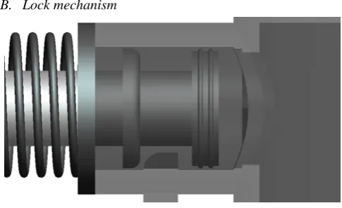
B. Lock mechanism
[image:1.595.312.555.617.765.2]
Fig 1-Lock mechanism
Variable Volume Engine with Combined
Advantage of Supercharging and Variable
Compression
The extended cylinder at their bottom consists of a slotted cut. A lock will be present through this slot. The working of this lock will be by spring and the cam. There is a sliding surface on one side of the lock. Another surface will be straight and flat. This sliding arrangement allows the sub piston to move towards the main cylinder i.e. piston will slide over the lock and spring gets compressed. Since another surface is straight, lock will not allow the piston to move apart from the main cylinder. On compressing spring by cam, the lock will come down and then only the piston will move from the main cylinder without any obstacle.
III. WORKING
Let us start the working principle from the power stroke. Gas will expand only on the main piston. Thus mechanical power is transmitted to the flywheel only through the main piston. The volume of the cylinder during the starting of the power stroke is the combustion chamber volume. This is same as conventional engine. Then exhaust stroke starts and exhaust gas is allowed to escape out through exhaust valve. Then suction stroke starts. During this stroke, main piston sucks the air or air fuel mixture. Along with the main piston, sub piston also sucks air or air fuel mixture. The motion to the sub piston is given by the cam shaft through cam against the spring load. As the sub piston sucks air or air fuel mixture, the lock is pressed down from the slot by another cam. At the end of the suction stroke, the volume of the cylinder is sum of volume of the main cylinder and the volume of the extended cylinders. This will be the volume at the start of the compression stroke. Compression starts from this volume and ends at the conventional combustion chamber volume. During this stroke along with the main piston, sub pistons also compress the air or air fuel mixture. The motion to the sub piston is due to the expansion force of the spring. During the forward motion of the sub piston, it slides over the lock and compresses the air or air fuel mixture. At the end of the compression stroke, sub-piston will be locked by the lock mechanism. Thus power acts only on the main piston. Thus
this cycle continues and during the other two strokes, the sub pistons will not be under motion. These sub pistons due to the lock will not move during gas burst arising at the power stroke. At last, the power is only developed on the main piston.
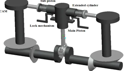
[image:2.595.305.539.137.266.2]A. Lock mechanism
Figure 2-Extended cylinders
Only after the instant when the main piston crosses the axis of the extended cylinders, the sub pistons start to suck the air or air fuel mixture. Otherwise the movement of the sub pistons will not result in suction thereby causing only vacuum below the piston. At last it results in causing opposing force to the engine.When the main piston crosses the extended cylinder - projected area of the main cylinder, the piston rings of the main piston may get affected. Thus the extended slot of the main cylinder should have some smoothness so that piston rings of the main piston will not get affected. Also there won’t be any problem on splashing and cleaning of the lubrication oil along the main cylinder extended surface area. When the last ring splashes along the concave surface of the sub piston and when the main piston moves downwards, the other compressor rings of the main piston will clear the oil from the sub piston surface while crossing.
[image:2.595.50.486.517.768.2]B. Supercharging
Supercharging is the process of increasing the volumetric efficiency of the engine. The present mode of increasing the volumetric efficiency is by turbo charging. Through the expansion of exhaust gas, some work is derived by the turbine. This work is used to run the compressor separately. This compressor compresses the air or air fuel mixture, and supplies it to the cylinder under pressure. In variable volume engine, this whole system’s work is done by the sub pistons. When compression stroke starts, motion to these sub pistons is given and when these sub piston moves, along with the main piston it sucks the air or air fuel mixture. Thus when compared to the conventional engine, variable volume engine takes in more air or air fuel mixture. At the end of the compression stroke, the combustion chamber volume is same as in the convention engine and variable volume engine. This is due to the reverse movement of the sub pistons. Thus supercharging is achieved by single arrangement rather then using compressor and turbines. By controlling the extended volume i.e. by controlling the stroke length of the sub pistons, some amount of air or air fuel mixture is drawn inside the cylinder. Usually feed back from the speed of the engine is given to control the amount of extra air or air fuel mixture by supercharging.
C. Variable Compression Ratio
Compression ratio is defined as the ratio of total volume to combustion chamber volume. Usually, engines will have constant compression ratio. In order to make variable compression ratio, either total volume or the combustion chamber volume should be made variable. In the present mode, combustion chamber volume is made variable. This is achieved by adjusting the TDC. In variable volume engine, total volume is made variable. When compression stroke starts, volume of the engine gets increased. Thus compression ratio in variable volume engine is defined as the ratio of sum of volume of main cylinder and extended volume (due to sub-piston) to the combustion chamber volume. Thus in order to make compression ratio a variable, stroke length of the sub pistons is adjusted to control the extended volume. Increasing the stroke length leads to an increase in the extended volume, thus increasing the compression ratio. Thus variable compression ratio and supercharging can be achieved by this variable volume engine by using sub pistons. The only condition is that the inlet valve should be closed. Otherwise sub pistons will not compress but will force the air or air fuel mixture through inlet valve.
IV.MODIFIED OTTO AND DIESEL CYCLE
A. Otto cycle
In order to find the work done by modified Otto cycle, suction temperature is required. Thus temperatures at all the stages are found out using this suction temperature and compression ratio. Then work done by the cycle and efficiency of the cycle can be found.
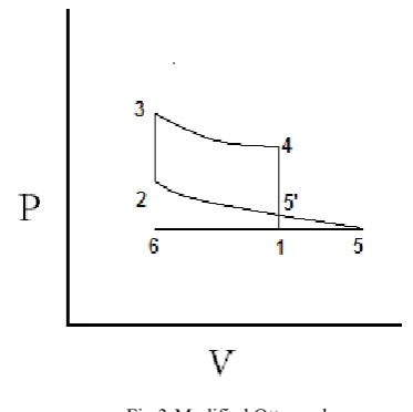
6 – 5 —› Suction Process
5 – 2 —› Isentropic Compression Process
2 – 3 —› Constant Volume Heat Addition Process 3 – 4 —› Isentropic Expansion Process
[image:3.595.327.514.54.240.2]4 – 1 —› Constant Volume Heat Rejection Process
Fig 3-Modified Otto cycle
Let us consider that all suction temperature and volume to be known. Let,
r – Actual compression ratio rm - modified compression ratio Q – Actual heat input in kJ Q1 – increased heat input in kJ a – Extended volume in m3 Cf – calorific value in kJ/kg
Vn –volume of cylinder at different stages as shown in figure 3 in m3
Tn - temperature of charge at different stages as shown in figure 3 in K
Cv- Specific heat in kJ/kgK m – mass of charge in kg η – Overall efficiency Q° = (V+a) × Cf/15 = Q + Q1
Q1 represents the increased Heat due to supercharging
Q represents the conventional Heat (if Main piston sucks Air- Fuel mixture)
Where ‘a’ is the extended volume and CV is the calorific value and considering specific ratio as 1:14
Q1 = (V-a)CV/15
From The graph it is known that V1/V2 = r and V5/V2 = rm Also V5 = 5 V1/4
rm = 5 V1/4V2
Hence rm = 5r/4 (1)
T2/T1 = (V5/V2) (γ-1) (2) Thus (V5/V2)= (rm) (γ-1) (3)
Substituting (3) in (1),
(V5/V2)(γ-1) = (5/4) (γ-1) × r (γ-1) (4) Substituting (4) in (2),
T2/T1 = (5/4) (γ-1) × r (γ-1)
Hence, T2 = (5/4) (γ-1) × r (γ-1) × T1 (5)
Due to SUPERCHARGING, Q gets increased by Q + (Q1) Q = m × Cf
Q° = CvdT Q° = Cv (T3 – T2) Q° + Q°/4 = Cv (T3 – T2)
T3 = {(Q+Q1)/Cv} + T2 (6) Substituting (5) in (6),
T3 = {(Q+Q1)/Cv} + (5/4) (γ-1) × r (γ-1) × T1 (7) We know that,
T4 = T3 × (V2/V1) (γ-1) = T3 × (1/r) (γ-1) (8) Substituting (7) in (8)
T4 = [{(Q+Q1)/Cv}× (1/r) (γ-1) ] + [T1 × (5/4) (γ-1) ] (9)
B. Diesel Cycle
[image:4.595.309.543.539.716.2]Fig 4-Modified Diesel cycle
From the PV Diagram, we infer that V1/V2 = r and V5/ V2 = rm We consider {V1 + (V1/4)} = V5
Hence, modified compression ratio in terms of conventional compression ratio rm= 5r/4
The temperatures at the various positions of the diesel cycle are
T2 = T1 × (5/4) (γ-1) × (r) (γ-1)
T3 = [T1 × (5/4) (γ-1) × (r) (γ-1)] + [Q+ Q1]/ Cp
T4 is found out using pressure temperature relation, ideal gas equation and volume temperature relation for isentropic expansion process
T4 = {[(T1 × (5/4) (γ-1) × (r) (γ-1)) + (Q+ Q1)/ Cp] / V1(γ-1) } × {mR × (T1 × (5/4) (γ-1) × (r) (γ-1)) + (Q+ Q1)/ Cp] }(γ-1)
η = 1-(1/ (r1) (γ-1) where r1 = V2/V3 and r = V1/V3
C. Indicated Power and Brake Power of the Variable Volume Petrol Engine
Relative Efficiency = Indicated Thermal Efficiency/ Ideal Efficiency
Relative efficiency of Otto cycle will be around 50% Thus indicated thermal efficiency will be half of the ideal efficiency.
Ith = 0.5 × 1-(1/ (r1) (γ-1)
We know that Indicated Thermal efficiency = Indicated Power / Fuel Power
IP = mf × Cf × 0.5 × 1-(1/ (r1) (γ-1)
Considering the Stoichiometric ratio as 14:1, the mass of the fuel will be 1/15th of the total air fuel mixture sucked by the main piston and the sub pistons during the suction stroke. ρ = m/V; Mass of the fuel = Density of the air fuel mixture / Volume during sub-Pistons at extreme position of suction stroke
Indicated power Ip = ρ ×V2 × Cf × 0.5 × 1-(1/ (r1) (γ-1) Indicated Mean Effective Pressure = IP / (A × (N/60) × L) When L = L/3 during compression stroke, sub-pistons get locked by lock mechanism, thus work-done to the sub-piston is obtained by using IMEP at this position and volume of the extended cylinders.
Extra Pressure × a × L/3 × N/60 = Extra Work given to the sub-pistons.
The same mass flow rate in order to be done by supercharging is m = PV2/RT
From this, pressure at the exit of the compressor is found out and the work done required by the compressor in
supercharging for supplying same mass flow rate is W= (P1V1 - P2V2)/ (γ-1) power transmission. But compressor efficiency is
D. Indicated Power and Brake Power of the Variable Volume Diesel Engine
η = 0.5 × {1- [1/(γ×(r)(γ-1))] × (rcγ–1)/(rc–1)}
Indicated power = mf × Cf × 0.5 × {1- [1/(γ×(r)(γ-1))] × (rcγ–1)/(rc–1)}
IMEP = mf × Cf × 0.5 × {1- [1/(γ×(r)(γ-1))] × (rcγ–1)/(rc–1)} / (
A × L × N/60 )
Extra pressure = mf × Cf × 0.5 × {1- [1/(γ×(r)(γ-1))] × (rcγ–1)/(rc–1)} / (A×L/3×N/60 )
Extra work = mf × Cf × 0.5 × {1- [1/(γ×(r)(γ-1))] × (rcγ–1)/(rc–1)} / (A× a )
Brake Power = IP–(μ×IP); where μ is the coefficient of friction between the main piston and the internal cylindrical surface
V. RESULTS AND DISCUSSION
A. Petrol Engine
Let us consider a variable volume engine with 100cc+ (0 to 40cc). The stroke length of main piston is 5cm and the stroke lengths of the sub pistons are considered as (5/3) cm. It means that sub pistons are locked when main piston and sub pistons travels (5/3) cm of the compression stroke. The indicated mean effective pressure at this position is calculated. Using this indicated mean effective pressure and the volume of the sub piston, the power supplied to the sub pistons for compression can be found out. The power required to supply the compressor to supply the same mass flow rate as done by the extended volume is found out and compared. Usually reciprocating compressors will be having more efficiency than the other centrifugal compressor. Thus for comparison, reciprocating compressor power input is considered. The efficiency of the sub piston is considered as 0.9. The reason is simple as it involves only power transmission. However, the compressor efficiency is around 0.5.
Fig 6 Extra work vs. Extended volume
[image:5.595.52.291.59.473.2]Fig 7 Brake power vs. extended volume
Fig 8 Indicated power vs. Extended volume
Fig 9 Indicated pressure vs. extended volume
B. Diesel Engine
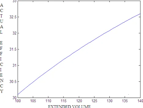
Let us consider a variable volume diesel engine with volume ranges from 160 to 220cc. hence compression ratio varies from 16 to 22. Cut off ratio is considered to be 2. In diesel cycle, supercharging increases only mass of the air. Thus heat supplied will not vary with extended volume. Thus from the graph it seems that efficiency increases only due to the increase in compression ratio. The mass flow rate of the fuel is considered as 0.03 kg/sec. It is found from the graph that indicated power of the engine increases 810kJ to 870kJ. The increase is only due to the increase in efficiency of the engine primarily due to the variable compression ratio.
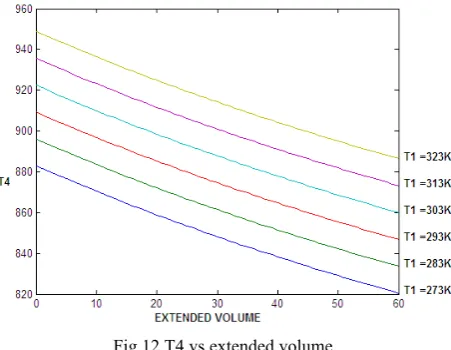
The fact behind the increase in efficiency of the engine (both petrol and diesel) is found out from the pv diagram i.e. from Otto cycle and diesel cycle. It is seen that all other stage temperatures except T4 gets increased as the extended volume increases. But temperature T4 decreases as the extended volume increases. Thus, it is found that the heat rejected decreases as extended volume increases. Thereby, the work done also increases due to the decrease in Heat rejection.
[image:5.595.310.550.507.691.2]
Fig 11 Indicated power vs Extended volume
Since Indicated Power of the engine Increases due to the increase in the extended volume ( and with constant mass of fuel supplied) Brake power also increases due to the Mechanical Efficiency of the engine.
Fig 12 T4 vs extended volume
Our next task is to analyze the performance of the variable volume engine with the turbocharger. The work output of the turbocharger is given to the supercharged compressor in order to increase the volumetric efficiency which would be compatible for sports vehicles.
REFERENCES
[1] Yunus A. Cengel, Michael A. Boles, “Thermodynamics: an engineering approach”, Tata Mcgraw Hill publishing company ltd, New Delhi, isbn 0-07-060659-5
[2] P.K. Nag, “Basic and applied Thermodynamics”, Tata Mcgraw Hill publishing company ltd, New Delhi, isbn 0-07-047338-2
[3] Hou, S.S. Comparison of performances of air standard Atkinson and Otto cycles with heat transfer considerations, Energy Conv Manage 2007;48:1683–1690.
[4] Leff HS. Thermal efficiency at maximum work -output: new results for old heat-engines Am J Phys 1987;55(7):602–10
[5] Mozurkewich M, Berry RS. Optimal paths for thermodynamic systems: the ideal Otto-cycle. J Appl Phys 198 2;53(1):34–42. [6] Ozso ysal, O.A. Heat loss as percentage of fuel’s energy in air
standard Otto and diesel cycles. Energy Conv Manage 2006;47(7–8):1051 – 1062
[7] Wu, C., Blank, D.A. Optimization of the endoreversible Otto cycle with respect to both power and mean pressure. Energ y Conv Manage 1993;3 4:1255–1259
[8] Aragon-Gonzalez, G., Ganales-Palma, A. Leon -Galicia, A., Maximum irreversible work and efficiency in power cycles. J Phys D: Appl Phys 2000;33(11):1403–1409
[9] Ge Y, Chen L, Sun F. Finite time thermodynamic modeling and analysis of an irreversible Otto cycle. Applied Energy 2008a;85(7):618-624
[10] Heywood JB. Internal combustion engines fundamentals. New York: McGraw-Hill, 1 988.
[11] F Angulo-Brown et alCompression ratio of an optimized air standard
Otto-cycle model Eur. J.
Phys.15 38-42 doi: 10.1088/0143-0807/15/1/007
[image:6.595.62.288.337.512.2]