Abstract-Most commonly used methods of
anticorrosion protection of large metal structures are painting and metal spraying. Painting is considerably cheaper than metal spraying, but the latter gives structures protection up to 20 years and reduces maintenance costs substantially. Metal spraying is typically achieved by spraying of molten zinc, aluminium or their alloys using thermal spraying technologies, such as Wire Flame and Twin-Wire Arc. However, the drawback of these methods is a relatively low bonding strength and porosity in coatings, which reduce their efficiency in the areas of mechanical contacts and highly corrosive environment.
There were attempts to use high velocity processes, for example, the High Velocity Oxy Flame (HVOF) process, which produces higher flow and particles velocities and, therefore, higher bond strength of coatings. However, this method does not lend itself for applications on-site where anticorrosive protective coatings are typically applied. In addition, the HVOF process generates temperatures far above the melting temperatures of zinc and aluminium, which can cause excessive oxidization of sprayed materials. On the other hand, the High Velocity Air Flame (HVAF) process has lower flame temperatures, simpler system design, lower running costs and it can be applied for thermal spraying of various materials.
This paper presents a development of the thermal spraying system built on the principles of the HVAF process. The designed thermal gun is used for thermal spraying of Zn-Al wire, which is melted in the combustion zone and accelerated by a supersonic flow in the converging-diverging nozzle. HVAF sprayed coatings showed considerably higher bond strength than coatings obtained by the conventional methods indicating the advantage of this method in areas where the adhesion strength is critically important. Highly dense structure of the coating obtained with HVAF eliminates a need for a top paint coat, which is typically applied on metal sprayed coatings to extend service life. In addition, the developed thermal spray system provides competitive spray rates, high deposition efficiency, and the process can be easily performed on-site. Lower operating costs of the HVAF process in comparison with other high velocity systems, makes this technology viable for thermal spraying applications for anticorrosion protection.
Index terms-Surface protection, Thermal spraying
I.A. Gorlach is with the Mechatronics Department, Nelson Mandela Metropolitan University, Port Elizabeth, South Africa (e-mail: [email protected]).
I. INTRODUCTION
With the rapid development of modern industry, quality of surfaces of structures, products and components are important from many aspects such as, reliability, surface life, maintenance and economics. A local failure on the surface usually causes the entire component to be rejected or it may lead to a failure of a machine or structure. It is estimated that in the developed countries, the loss caused by corrosion is up to 2-4% of Gross National Product [1]. Thus, many countries have taken great efforts in improving the surface performance of parts in order to enhance the reliability of mechanical equipment parts and prolonging their service life.
II. THEORETICAL RATIONAL
The most economical way of protecting the base material against corrosion is by applying a coating layer of material, which is resistant to corrosion. Coating must be able to withstand not only specific environmental conditions but also fulfil certain mechanical properties. For these reasons, widely used corrosion resistant materials include metals, such as zinc, aluminium or their alloys, of which Zn/85 Al/15 is the most common, and it gives better performance than just zinc or aluminium coatings. Hot dip galvanization as a coating process has a number of limitation, which makes it not suitable in many applications, which include; limiting coating thickness, product size limitations and no possibility of application on-site when a structure is assembled to coat joints and fasteners. In addition, thermal sprayed Zn-Al coatings are free from iron, which is usually present in galvanized coatings.
The first thermal spray process was developed by M.U. Schoop and H. Guenther in 1910 [2]. The flame spray method uses the chemical energy of combustion of gaseous fuel and oxygen to generate heat to melt coating materials, which can be in the form of powder, wires or rods and are fed into the flame, and sprayed by the expanding gas flow onto the substrate. Wires are widely used as the feedstock material, and the process is referred to as the Wire Flame process. The advantages of the Wire Flame process include a basic system design and operation, low costs and versatility.
Development of the Thermal Spraying Process
for Anticorrosion Surface Protection
The process limitation is the speed with which the wire can be melted in the torch without compromising coating quality, which usually deteriorates with high speed when big chunks of semi-molten material are deposited.
A twin wire system, referred to as Twin-Wire Arc, uses a direct-current electric arc, struck between two consumable electrode wires to achieve direct melting of the material. A compressed air jet, located behind the wire tips, sprays the molten material that continuously forms as the wires are fed into the arc. The atomizing air is also used to accelerate the particles towards the substrate surface. The main advantage of this method, unlike the other techniques of thermal spraying, is that it minimizes the substrate heating and allows spray coatings onto polymers, fiberglass, wood, glass or paper products. Also, the Twin-Wire Arc process provides the highest spray rate of all thermal coating processes, particularly of Zn-Al wires.
Wire Flame and Twin-Wire Arc techniques are classified as low velocity processes since the carrier gas or air has a low velocity and as a result low particles velocity is obtained in comparison with other spray techniques. It is generally accepted that the main drawbacks of these processes are the low coating density and the low bond strength due to the low kinetic energy of the particles. For example, the coating bond strength of the Zn/85 Al/15 alloy obtained with the Twin-Wire Arc process usually does not exceed 8~9 MPa [3].
In order to improve the bond strength of coatings, there were attempts to use high velocity processes for thermal spraying of anticorrosion materials, such as; a hybrid HVOF-Arc system and the Cold Spray process. The HVOF process introduced in the 1960s, is based on combustion of fuel with oxygen in a combustion chamber and expansion of gases in the de Laval nozzle producing supersonic gas flow, which is used to propel particles injected into the flow [2]. Although HVOF can be used for spraying of Zn-Al alloys, it does not lend itself for applications on-site where anticorrosion coatings are typically required. In addition, the HVOF process generates temperatures far above the melting temperatures of zinc and aluminium, which can cause excessive oxidization of sprayed materials when entering the open stream. In some instances, shroud gas (nitrogen or helium) is used to shield the spraying stream, but this complicates the overall system. Recently the Low Temperature High Velocity Oxygen-Fuel (LTHVOF) system was reported, where the combustion temperature is reduced by injecting nitrogen into the
melting point, such as copper at the temperature in the combustion zone of 800K. The drawback of this method is that it is used only for powders, which usually provide lower spraying rates in comparison with spraying wires.
A hybrid HVOF-Arc system, which was recently reported in literature is a combination of the Twin-Wire Arc and HVOF processes where consumable wires are molten by electric arc and then accelerated by a high velocity jet generated with HVOF instead of the compressed air [5]. Hybrid HVOF-Arc systems were developed for improving the bond strength of coatings of parts in the workshop environment, while the majority of applications is on-site, which limits this method.
Cold Gas Dynamic Spraying technology or Cold Spray was developed in mid-1980s at the Institute of Theoretical and Applied Mechanics of the Russian Academy of Science in Novosibirsk by Dr. Anatolii Papyrin and colleagues [6]. In the Cold Spray process, compressed gas accelerates small (1-50 μm) particles to a high velocity (300-1200 m/s). In Cold Spray, compressed gas (1.5-3.5MPa), usually nitrogen, is divided into two sections. One is heated up to 373-873K by electric heater and directed into the chamber, and accelerated by the de Laval nozzle to supersonic velocity. The other section of compressed gas is used to convey the powder from a powder feeder into the chamber and inject it before the convergent section of the nozzle. The particles are heated to temperature, which is lower than the melting point of the spray material, so oxidation is minimised. In order to produce high performance coating, particle velocity must exceed a critical value, which is 500-900 m/s depending on particle size, otherwise, particles rebound from the substrate. However, the results showed that Cold Spray is not suitable for spraying Zn-Al alloys due to high costs and a difficulty of building a portable system [7].
III. HVAF VERSUS HVOF
Generally, in order to obtain dense coatings with a high bond strength, a high velocity spray process is required, i.e. the higher the particles velocities, the better coating quality. High velocity spraying technologies include HVOF, HVAF, Cold Spray and the detonation gun (D-gunTM) techniques. HVAF was
developed before HVOF and used for cutting rocks by thermal spallation and later for thermo-abrasive blasting [8]. The D-gunTM was developed in 1980s for
mainly due to the economic reasons, whereas is HVAF is considerably less expensive because it is based on combustion of fuel with air.
HVOF produces higher flow velocity than HVAF, however, the flame temperature is also much higher in HVOF, which causes oxidization of spraying material. HVOF and HVAF are similar in the way that both methods employ combustion process of fuel under pressure to obtain high velocity flows, but their designs are significantly different. The combustion chamber of a HVOF system is a water cooled burner or a torch, where fuel (liquid or gaseous) and oxygen are injected axially, mixed and burned producing combustion gases, which are then accelerated in the converging-diverging nozzle (Fig 1a). A HVAF combustion chamber is designed on the principles of a jet engine combustor working on liquid fuel and compressed air, which is supplied to the combustion zone in two stages; a primary air for combustion and secondary air for cooling of the flame because the stoichiometric temperature of the air/paraffin mixture is too high for the combustion chamber housings and the nozzle (Fig 1b). Hence, the design of a HVAF thermal gun is more complex since the compressed air fed into the thermal gun should provide stable, efficient combustion and cooling of the thermal gun parts at the same time. Correct air passages inside the thermal gun and their dimensions are critical for the HVAF system performance.
The HVAF process is governed by the thermodynamic cycle derived from an air-standard Brayton cycle, i.e. combustion at constant pressure and expansion in the nozzle. Compressed air is supplied to the thermal gun from an external source, e.g. an air compressor. Combustion of fuel, mostly liquid fuels, takes place inside the combustion chamber, which follows by the expansion of gases in the de Laval nozzle. Using the standard analysis for compressible flows in ducts and the basic assumptions for the ideal gas, the geometry of the combustion chamber and the exit nozzle are derived to achieve the required gas flow parameters with the aims to: • achieve stable and complete combustion; • achieve temperatures sufficient for melting of
sprayed materials;
• obtain high gas exit velocity at the flow rate sufficient to propel coating materials. High velocity oxy and air flame systems use mainly paraffin as a liquid fuel, usually Jet A-1. The empirical formula of paraffin is CnH2n+2, where n is
the number of carbon atoms. The chemistry of combustion and specifically ignition of paraffin or
diesel is quite complex and is described according to some sources by 39 elementary chemical reactions and 28 species [9]. The stoichiometric mixture of paraffin and oxygen has an adiabatic flame temperature of 3300K and the heat of combustion of 37 MJ/l of paraffin. A typical HVOF system operates at 12 l/h of fuel and 56 m3/h of oxygen producing
approximately 125 kW of power of which 40% is the heat that needs to be dissipated [10]. Therefore, a sufficient water cooling system for HVOF is critically important and it contributes substantially to the operating costs.
The adiabatic flame temperature for the stoichiometric mixture of paraffin and air is approximately 2300K. However, the combustion process of HVAF, similarly to the combustors of jet engines, runs at a significantly higher air/fuel mixture than the stoichiometric value. The flame is diluted by the air before entering the nozzle in order to avoid overheating of air cooled components and the maximum flame temperature inside the thermal gun is estimated as 2000K [11]. The HVAF thermal gun, used in this research, consumes 8 l/h of paraffin using 180 m3/h of compressed air at 0.55 MPa pressure,
generating 80 kW without water cooling and therefore having higher efficiency and lower costs than HVOF.
Nozzle Water jacket
Spray material/nitrogen
Water out Fuel
Cooling water in Combustion chamber
Spray jet
a)
Nozzle
Fuel
Combustion chamber
Spray jet Air
Spray material/Air Oxygen
2800K
2000K
1300K
[image:4.612.167.448.77.276.2]b) 3300K
FIGURE 1. Schematics of a) HVOF burner and b) HVAF thermal gun (half cross-section)
IV. THERMAL SPRAYING SYSTEM
The main challenge in designing a HVAF system for spraying of Zn-Al alloys was to achieve the effective combustion process for melting the fed wire in such a way that it would provide efficient spraying process with minimum losses due to evaporation. The parameters, which determine the efficiency of the thermal spray process of Zn-Al wire include the
combustion process parameters, the wire entry position into the combustion zone, the wire feeding rate and the nozzle geometry. Coating quality and productivity of the spraying process are determined, among others, by the empirical parameters, such as a spraying distance, spray pattern, the linear speed of the gun and coating thickness of a single pass.
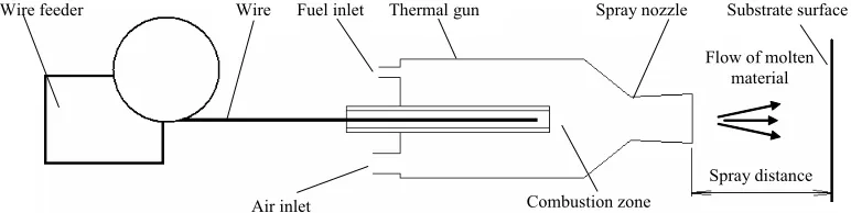
Spray distance Air inlet
Wire feeder Wire Thermal gun Spray nozzle Substrate surface
Flow of molten material Fuel inlet
Combustion zone
FIGURE 2. Diagram of the experimental set-up for HVAF thermal spraying of wire
The developed thermal spraying system consists of the HVAF thermal gun and the wire feeder. The thermal spraying gun is based on the design, which was previously developed for the thermo-abrasive blasting process and modified for the thermal spraying process [12]. The main features of the thermal gun include the combustion chamber, the wire guide and the nozzle. A high velocity flow is achieved by expanding, in the de Laval nozzle of high enthalpy gas obtained in the combustion process of burning liquid fuel and air inside the combustion chamber under
[image:4.612.102.488.422.519.2]rate and an entering position inside the combustion zone. Generally, a coating wire diameter that can be utilized by a system is determined by heat generated in combustion per unit time, the gas flow rate and the nozzle throat diameter. Since the thermal gun geometry parameters were fixed, the wire size of 2 mm diameter, as the most common size, was used in the experiments, although bigger diameter can also be sprayed.
Zn-Al wire is fed by an electric wire feeder through the rear of the combustion chamber employing a wire “push” type principle, which is efficient up to a 5 m distance between the wire feeder and the thermal gun, established experimentally (Fig. 2). If a longer distance is required, a “pull” type principle for wire feeding can be employed by means of adding a wire driving mechanism attached to the thermal gun similar to one used in Wire Flame systems.
The maximum speed of wire feeding was assessed on the basis of coating quality and determined experimentally as 5 m/min. Higher wire feed rates typically result in rougher surface finish with some partially melted pieces of material. Rougher coating surface would require more sealer, which is typically applied as a final coat on top of the metal coating to close possible pores and prolong service life. A lower wire feed rate is generally preferred as it provides smoother coating surface. However, it might cause significant material evaporation, lower deposition efficiency and slower spraying rates.
Another challenge in using a HVAF system for thermal spraying of Zn-Al wire is to eliminate clogging of the nozzle with molten material. In traditional Wire Flame and Twin-Wire Arc processes, wire is melted and sprayed directly without a nozzle, while in the HVAF thermal gun, wire is melted inside the thermal gun before entering the nozzle. The correct nozzle geometry, therefore, is not only important for achieving the highest multiphase flow velocity, but should also prevent adhesion of molten material to the nozzle inner walls.
V. Results and Discussion
In experiments, a 2 mm diameter Zn/85 Al/15 TAFALOY 02A was sprayed on steel substrates with the HVAF thermal gun. The wire was fed through the combustion chamber of the thermal gun by a wire feeder with a 5 m/min feed rate. Prior to thermal spraying, the steel samples were prepared by grit blasting using mineral slag, but not preheated or degreased in order to replicate the thermal spraying
conditions of real environment. The cylindrical steel samples were coated with a 150-200 μm thick layer for the adhesion test according to DIN EN 582.
The thermal spraying process was performed manually with consecutive vertical and horizontal passes. The spraying distance from the substrate surface was 300-350 mm leaving the temperature of the substrate relatively low, therefore cooling was not necessary during or after thermal spraying. The compressed air was obtained from a 35 kW diesel compressor producing up to 7 m3/min of air. Aviation
paraffin Jet A-1 was used as fuel.
An average spray rate of 6 kg/h with 2 mm diameter wire was obtained for coatings with smooth surface finish, which were compared with the samples sprayed with Twin-Wire Arc. Although the spray rate of 100 g/min is lower than typically reported for Twin-Wire Arc, it is believed that bigger wire diameters, up to 4,76 mm, can be used to increase spray rates in HVAF as the gas temperature and the flow rate generated by the thermal is sufficient to spray more material.
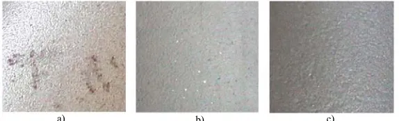
With a single pass, a 80-100 μm thick coating is deposited with a 0.5 m/min traverse speed of the thermal gun and the spray pattern of approximately 50 mm. This indicates that a single thermal spray coat would be sufficient for most applications as the specification typically requires a 80 μm thick protective coating. Figure 6 shows the sample, a corroded steel pipe, which was first grit blasted (Fig 3a), then sprayed with Zn-Al (Fig 3b) and following that painted over with a coat of sealer (Fig. 3c) to achieve a duplex coating system for extra corrosion resistance. Typical matte surface finish of the Zn-Al coating with some inclusions of aluminium on the surface can be observed on the sample. Eight samples were subjected to the slat spray tests according to ISO 9227 and showed no signs of corrosion after 14 days of testing.
a) b) c)
FIGURE 3. Picture of the sample; a) grit blasted, b) with Al coating and c) with sealer coating on top of
Zn-Al coating (duplex coating)
VI.Conclusion
In this paper, a new technology for anticorrosion protection is presented. The HVAF process can be efficiently used for thermal spraying of Zn-Al to produce coatings of high quality and productivity. The HVAF system uses paraffin and compressed air for combustion to melt and spray Zn-Al wire. The spray rate of 6 kg/h is achieved using a 2 mm diameter Zn/85 Al/15 wire without compromising coating surface finish, which is considerably lower than 9.5 kg/h typically reported for Twin-Wire Arc. However, bigger wire diameters can be used to increase spray rates in HVAF as the gas flow rate would allow that. A typical coating thickness of 80-100 μm with the spray pattern of 50 mm in diameter is obtained in a single pass of the thermal gun with a 0.5 m/s traverse speed, while thicker coatings can be easily obtained by adding layers of material.
The obtained coatings have low porosity, and possess very good adhesion to steel substrates with an average adhesion tensile strength of 16.5 MPa, which
is considerably higher than for Zn-Al coatings typically obtained with Twin-Wire Arc systems. Tests also indicated that the coatings have good corrosion resistance, which can be attributed to a dense and homogeneous layer morphology as a result of high particles velocities obtained in the HVAF jet.
During HVAF thermal spraying, the substrate is not subjected to high temperatures because of the long spray distance, the high spray rate, large spray patterns and short dwell time. This is a definite advantage of this method indicating that substrates with low melting point, such as bronzes, plastics, plaster, and wood, can be coated. Parts made of such materials often require metallic protective coatings. For example, in metal faced mould making, patterns made of plaster or wood are sprayed with zinc and backed up with epoxy. Up to now, metal faced mould making was only possible with Twin-Wire Arc.
REFERENCES
[1] Hangong, W., Xi’an, W. L., 2005. Thermal spraying-application and development trends. International Thermal Spray Conference, Basel, Switzerland. [2] Pawlowski, L., 1995. The science and engineering of
thermal spray coatings. Wiley, Chichester, England. [3] Varacalle, D.J., et al. 2005. Surface preparation of steel
substrates using Grit-Basting. International Thermal Spray Conference, Basel, Switzerland.
[4] Zha, H. Wang, B.Z., K. Xu, K., 2005. The
Microstructure and property of LTHVOF sprayed copper coatings. International Thermal Spray Conference, Basel, Switzerland.
[5] Kosikowski, D., Batalov, M. and Mohanty, P.S., 2005. Functionally graded coatings by HVOF-Arc hybrid spray gun. International Thermal Spray Conference, Basel, Switzerland.
[6] Papyrin, A.N., Alkimov, A.P., Kosarev, V.F., and Nesterovich, N.I., 1990. Method of Applying Coatings. Russian Patent No. 1,618,778, (priority of the Invention June 6, 1986).
[8] Turns, S.R., 2000. An Introduction to Combustion. 2nd Ed. Boston: McGraw Hill.
[9] Warnatz, J., Chevalier, C., and Müller, U.C. 1990. Auto-ignition in a non-premixed turbulent flow field, IDEA Project. Periodic Report No. 3, pp. 143-150. [10] Tafa JP-5000 Training manual. www.
http://www.praxair.com/praxair.nsf
[11] Gorlach, I.A., 2006. Modelling of an Efficient Nozzle Geometry for Thermo-Abrasive Blasting. R&D Journal, Vol 22 No 1, pp. 11-20.