Abstract—A stable grasp can only be achieved with multi-fingered grippers. The required task for the robots has become more complicated such as handling of objects with various properties e.g. material, size, mass etc. and the physical interaction between the finger and an object has also become complicated e.g. grasping with slippage, finger gait ….. etc.
This paper focuses on enhancing the grasping ability with better sensors backup, which can enable the robot to deal with real life situations. Design procedure, Solid modeling, Force analysis and simulation have been discussed for further dynamic analysis towards confirmation of the viability. This is an effort to design gripper by experimenting with various designs for developing the universal dexterous grasping.
Index Terms — Grasp, Under actuated, Dexterous Grasping,
Universal Gripper, Simulation
I. INTRODUCTION
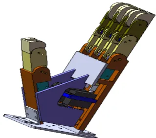
[image:1.595.83.243.492.633.2]In an underactuated robotic hand, the number of actuators is less than the degrees of freedom (DOFs) of hand. The mechanical intelligence embedded into the design of the hand allows the automatic shape adaptation of the fingers. The underactuated DOFs are, in this case, governed by mechanical limits. No special control is needed.
Fig. 1. Three-Dimensional View of Multifingered gripper
Each finger has three degrees of freedom and one actuator (motor). Thumb has two degrees of freedom and one actuator. Thus, there are total 11 degrees of freedom and 4 actuators
S. S. Ohol with Mechanical Engineering Department, College of Engineering., Pune, INDIA ( phone: 091-020-25507234,229; fax: 091-020-7299; e-mail: [email protected]).
S. R. Kajale, was with Mechanical Engineering Department, College of Engineering., Pune, INDIA. He is now with the S.G.G.S Institute of Engg. And technology, Nanded, INDIA ( phone: 091-2462–229307; Fax: +91-2462-229236 email: [email protected])
for the actuation mechanism. The links provide the actuation to the successive joints. Therefore, separate actuation is not required at each joint. The links move inside the grooves cut in the phalanges, thus providing limits to the motion of the gripper.
II. LITERATURE SURVEY FOR SIMULATION OF A VARIOUS SIMILAR PART HANDLING SYSTEMS
A complete mathematical model of SCARA robot (Serpent 1) is developed by Yuru Zhang and William A. Gruver [1] including servo actuator dynamics and presented together with dynamic simulation. Using Lagrangian mechanics they have derived the equations of motion relating joint torques, positions, velocities and accelerations. Some simplifying assumptions like; no gear and transmission losses and friction in joints are taken while deriving equations of motion. D.C. servomotors driving each robot joint is studied with PD controller action. Serpent 1 robot is instructed to achieve pick and place operations of three different size cylindrical objects through assigned holes. The performance of robot actuator-control system is examined with numerical simulation and experimentally verified.
The influence of size and material properties of fingertips on the power –law equation for soft finger contacts has been investigated by Nicholas Xydas and Imin Kao [2].
The normal and tangential stiffness of soft materials have been experimentally investigated in order to demonstrate their suitability with the development of compliant pads for robotic hands by L. Biagiotti et. al. [3].
A kinematic model of a piezo actuated biologically inspired micro gripper design is proposed and a dynamic model based on Euler-Lagrangian approach is developed by Lionel Birglen, Clement M. Gosselin considering the system as combination of mass-spring-damper [4]. The mathematical model is then simulated using MATLAB/SIMULINK.
The simulator using IPC (Inter Process Communication) library based on TCP IP, is observed by Abdul Ghafoor, Jian S. Dai & Joseph Duffy [5]. It consists of the four units: communication, robot control, kinematic design, and driver for real robot operation. Implemented in the simulator are seven kinds of URC robots. By providing only the link parameters, a new robot can be added. Also, a user can generate a working environment consisting of walls. The real robots and virtual robots can operate in parallel. It is used for verification of collision avoidance algorithms in an environment with multiple heterogeneous robots.
A dynamic simulation package has been developed by M. Taylan Das, L. Canan Dülger, which can accurately model
Simulation of Multifinger Robotic Gripper for
Dynamic Analysis of Dexterous Grasping
the interactions between robots and their environment [6]. It creates a virtual environment in which various controllers and work cells can be tested. The simulator is divided into two parts: local objects that compute their dynamic equations of motion and a global coordinator that resolves interactive forces between objects. This simulator builds upon previous work on dynamic simulation of simple rigid bodies and extends it to correctly model and efficiently compute the dynamics of multi-link robots.
A kinematics’ model of a piezo actuated micro gripper design is proposed and a dynamic model based on Euler – Lagrangian approach is developed considering the system as a mass – spring – damper by Madhab G.B., Kumar C.S., Mishra P.K. [7]. They have also discussed the design of two fingered microgripper actuated by a pair of agonist and antagonist piezoelectric multilayer stack actuators. They have used genetic algorithm based approach for optimization of gripping forces.
III. MODELING OF COMPONENTS
A wide range of components can be modeled in the SolidWorks. The components can be assigned specific material like Aluminum. The position of the components is fixed relative to each other using coincident and/or concentric or parallel mates. The interferences in the assembly are detected using the Interference Detection command. The weight of the components or of the entire assembly can be measured using the Mass Properties option.
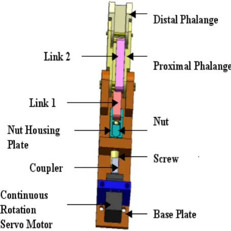
Fig. 2. Inside view of a Finger
The continuous rotation servomotor provides the torque to the power screw through a flange coupling. The power screw converts this rotary motion into translational motion of the nut and nut housing plates. As the nut and nut housing assembly slides, link 1 rotates about joint 1, applying torque to proximal phalange at joint 2 about joint 3. Hence, proximal phalange rotates about joint 3. Thus, actuation is provided to the proximal phalange by link1. The proximal phalange in
turn actuates link 3 and middle. Hence, the middle phalange rotates about joint 3. The link 2 rotates about joint 4 as the middle phalange rotates about joint 3 , thus, applying torque to the middle phalange at joint 5 about joint 6. Hence, the middle phalange rotates about joint 6. Thus, actuation is provided to the middle phalange together by the proximal phalange and link 1. Now the middle phalange actuates the distal phalange at joint 9 and link 3 provides torque to the distal phalange at joint 8 about joint 9. Hence, the distal phalange rotates about joint 9. Thus, the middle phalange and the link 3 together actuate the distal phalange.
Thus, the links apply torque to the successive phalanges about the phalanges’ pivot points.
The steps for perfect grasp
a) Object Details – Identifying the type and position of object to be grasped.
b) Grasping Mode – Deciding the suitable gripper position and configuration for type of object and the assigned task. c) Positioning – positioning the gripper as per the
object orientation.
d) Grasp action – performing the grasp for object with the help of feedback inputs. Synthesis for perfect grasp
Following information is needed to develop an anthropomorphic multifingered robotic hand
a) Mechanisms required b) Sensors required for feedback inputs c) Drive required
[image:2.595.61.288.419.645.2]d) Interfacing circuitary
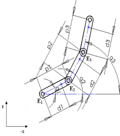
Fig. 4. Co-ordinate system for Gripper
Fig. 5. Co-ordinate system at Grasping action
Consider the gripper grasping an object between its middle finger and the thumb. The orientation of the gripper is such that the mass of the finger and thumb is acting downwards along y axis of gripper. The motion of the fingers is in the x-z plane ( ref. fig.5 )
Fig.6. Assembly view of dexterous grasping.
The force analysis of the finger for grasping an object of m kg has been done.
IV. GRIPPING FORCE AT THE FINGER TIP
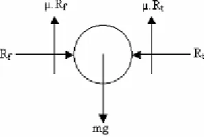
Consider free body diagram of the object to be grasped. The weight mg of the object acts in downward direction, parallel to the surfaces of the finger and thumb.
Fig. 7. Free body diagram of object
Let Rf and Rt be the reactions of the finger and thumb
respectively on the surface of the object.
Rf = Rt
Let µ be the coefficient of friction between the gripper surface and the object surface. Then,
µ. R f + µ.R t = mg ….(1)
Hence, 2 µ. R f = mg (since Rf = Rt)
Hence, Rf = mg / 2 µ ….(2)
Thus, the grasping force (
30 P
F
) required at the finger tip of the gripper is30 P
F
= mg / 2 µ ….(3)It means the distal phalange should exert this force on the object in the x-z plane.
The position of the finger while gripping the object is as shown in fig. 6. Let Ø1, Ø2 and Ø3 be the angles made by links
1, 2 and 3 respectively with x axis and L1, L2 and L3 be their
lengths. Let q1, q2 and q3 be the angle made by the proximal,
middle and distal phalanges respectively with x axis respectively and P1, P2 and P3 be their lengths.
3 P
F
2
P stands for the force exerted on distal phalange (P3)
by middle phalange (P2) and αP3 P2 stands for the angle
between distal phalange (P3) and middle phalange (P2).
Subscript B stands for base, N stands for nut and O stands for object.
Distal phalange
Consider free body diagram of the distal phalange.
Forces along x axis,
3 P
F
3
L cosØ3 -
F
P3 P2 cos αP3 P2+F
P30cos α0 = 0…. (4) Forces along z-axis,
-3 P
F
L3sin Ø3 +F
P3 P2sin αP3 P2+F
P30sin α0 = 0…. (5) Taking moment about E3,
3 P
F
3
L cosØ3 .a sin (135 - q3) +
F
P3 L3sin Ø3.a cos (135 -q3) -
F
P30sin α0.p3. cos q3 -F
P30cos α0.p3. sin q3 = 0…. (6)
Thus, we get 3 equations with three unknowns viz.
3 P
F
L3 ,F
P3 P2and αP3 P2. Hence, these 3 equations i.e.equation no. 4, 5, & 6 can be solved to find out respective values.
Consider free body diagram of link 3.
Forces along link 3,
3 L
F
P2=F
L3 P1Now, we have one equation with one unknown i.e.
3 L
F
1 P .
This equation can be solved to find its value. Consider free body diagram of link 1
[image:3.595.73.222.652.754.2]Forces along link 1
1 L
F
1
P =
F
L1 NThus, we get one more equation with one unknown
1 L
F
N. Hence, this equation can be solved to find out its value.Now
1 L
F
N is the force exerted by the nut on thelink 1. Hence, the load to be driven by the power screw (W) is
W =
1 L
F
NFrom this, we can determine the torque required by the power screw to drive the load. This is the torque supplied by the motor to the power screw.
Therefore using the actual values we get Forces along link 1
1 L
F
1
P =
F
L1 NHence,
1 L
F
N= 231.8841 L
F
N. cos Ø1 = 230.156This is the load to be driven by the power screw. Hence, W = 230.156 N
TORQUE FOR THE POWER SCREW,
Mean diameter of the screw, d = 7.3 mm Pitch of the screw, p = 1.25
Coefficient of friction between screw and nut,
µ = tan Ø= 0.15 ……… where Ø is the friction angle. µ2 = 0.12
055
.
0
3
.
7
25
.
1
.
tan
=
×
=
=
π
π
α
d
p
………. where α is
the helix angle of screw.
Since, the angle for Acme threads is 2ß = 29 º or ß = 14.5 º, therefore, virtual coefficient of friction,
155
.
0
9681
.
0
15
.
0
5
.
14
cos
15
.
0
cos
tan
11
=
=
β
=
=
=
μ
φ
μ
We know the force required to overcome the friction at the screw,
⎥
⎦
⎤
⎢
⎣
⎡
−
+
=
+
=
1 1 1
tan
.
tan
1
tan
tan
)
tan(
.
φ
α
φ
α
φ
α
W
W
P
N
748
.
48
155
.
0
055
.
0
1
155
.
0
055
.
0
156
.
230
=
⎥⎦
⎤
⎢⎣
⎡
×
−
+
=
Hence, torque required overcoming friction at the screw,
=
×
=
×
=
P
d
/
2
48
.
748
7
.
3
/
2
T
177.930 NmmHence, T = 0.17793 Nm
This is the torque to be supplied to the screw to grasp an object of 3 kg.
V. DYNAMIC ANALYSIS
For the dynamic analysis of gripper, we assume only the three phalanges viz. proximal, middle and distal. We replace the links with equivalent torques about the respective phalanges. The orientation of the gripper is as shown in fig. 8
As shown in fig. 5 each of the joints E1, E2 and E3 are
revolute joints. The absolute angles made by each of the phalanges with the x-axis are q1, q2 and q3 respectively. Let
p1, p2 and p3 be the lengths of the phalanges. Further, let d1,
d2, d3 be the distance of the center of mass of the phalanges
[image:4.595.317.547.346.605.2]from their respective joints, E1, E2 and E3 as shown in the
figure. Let I1, I2 and I3 be the moment of inertias of the three
phalanges about an axis passing through their center of mass and perpendicular to the plane of the robot’s finger, that is, along y axis. Finally let mp1, mp2 and mp3 be the masses of the
proximal, middle and distal phalanges respectively.
Fig. 8. Inclination of phalanges
The total kinetic energy of the proximal phalange is, K1
}
)
sin
(
)
cos
(
{
2
1
2 1 1
2 1 1
2 1 1
1 1
q
d
dt
d
q
d
dt
d
m
q
I
K
=
&
+
p+
1 12 12 12
2
1
2
1
q
d
m
q
I
&
+
p&
=
…. (7) [image:4.595.48.247.687.758.2]}
)
sin
sin
(
)
cos
cos
(
{
2
1
2
1
K
2 2 2 1 1 2 2 2 1 1 2 2 2 2 2q
d
q
p
dt
d
q
d
q
p
dt
d
m
q
I
p+
+
+
+
=
&
)
8
....(
)}
cos(
2
{
2
1
2
1
K
2 1 2 1 2 1 2 2 2 2 1 2 1 2 2 2 22
p
q
d
q
p
d
q
q
q
q
m
q
I
p
+
+
−
+
=
&
&
&
&
&
The total kinetic energy of the middle phalange is,
} ) cos ) sin sin ( ) cos ) cos cos ( { 2 1 2 1 2 3 3 2 2 1 1 2 3 2 2 2 1 1 2 3 3 3 3 q d q p q p dt d q d q p q p dt d m q I K p + + + + + + = &
)
cos(
)
cos(
[
2
{
2
1
2
1
3 2 3 2 3 2 2 1 2 1 2 1 2 3 2 3 2 2 2 2 2 1 2 1 2 3 3 3q
q
q
q
d
p
q
q
q
q
p
p
q
d
q
p
q
p
m
q
I
p−
+
−
+
+
+
+
=
&
&
&
&
&
&
&
&
)]}
1
cos(
3 3 1 31
d
q
q
q
q
p
−
+
&
&
…. (9)Hence, the total kinetic energy of the finger is,
K = K1 + K2 + K3 ... (adding eq. no. (7), (8) & (9) for K )
Further, the potential energy is given as,
)
sin
sin
sin
(
)
sin
sin
(
sin
3 3 2 2 1 1 2 2 1 1 1 1 3 2 1q
d
q
p
q
p
g
m
q
d
q
p
g
m
q
gd
m
P
p p p+
+
+
+
+
=
.... (10)It can be seen that the kinetic energy K is a function of
(
q
1,
q
2,
q
3,
q
&
1,
q
&
2,
q
&
3) while potential energy P depends on(
q
1,
q
2,
q
3).The lagrangian of the system is the difference between the kinetic and the potential energy given as,
)
,
,
(
)
,
,
,
,
,
(
)
,
,
,
,
,
(
3 2 1 3 2 1 3 2 1 3 2 1 3 2 1q
q
q
P
q
q
q
q
q
q
K
q
q
q
q
q
q
L
−
=
&
&
&
&
&
&
.… (11) Now, let the torques at the joints E1, E2 and E3 berespectively, T1, T2, T3 respectively.
Then the following Euler Lagrange gives the dynamics of the robot’s finger
Equations: 1 1 1
T
q
L
q
L
dt
d
=
∂
∂
−
⎭
⎬
⎫
⎩
⎨
⎧
∂
∂
&
…. (12)2 2 2
T
q
L
q
L
dt
d
=
∂
∂
−
⎭
⎬
⎫
⎩
⎨
⎧
∂
∂
&
….. (13)3 3 3
T
q
L
q
L
dt
d
=
∂
∂
−
⎭
⎬
⎫
⎩
⎨
⎧
∂
∂
&
….. (14)Hence, we firstly compute the lagrangian
L
(
q
1,
q
2,
q
3,
q
&
1,
q
&
2,
q
&
3)
in (11) by using the obtained expressions for the kinetic energy)
,
,
,
,
,
(
q
1q
2q
3q
1q
2q
3K
&
&
&
and the potential energy3 2 1
,
,
(
q
q
q
P
).We subsequently use the expression for the lagrangian
)
,
,
,
,
,
(
q
1q
2q
3q
1q
2q
3L
&
&
&
in the equations (12), (13), (14) toobtain the system dynamics. Thus,
1 1 3 1 2 1 1 2 1 2 1 1 2 2 2 3 3 1 1 3 1 3 1 3 1 2 2 1 2 1 2 1 2 2 3 3 1 3 1 2 2 1 2 1 2 1 1 2 1 3 2 1 2 2 1 1 1 1
cos
]
[
)
(
sin
]
[
)
(
sin
]
)
(
[
)
(
)
(
sin
]
[
)
(
cos
)
(
cos
]
[
]
[
q
g
p
m
p
m
d
m
q
q
q
q
p
p
d
m
q
q
q
q
d
p
q
q
d
p
q
q
q
q
q
p
p
d
p
q
q
q
d
p
q
q
q
p
p
d
p
q
p
m
p
m
d
m
I
T
p p p p p p p+
+
+
−
+
+
−
−
−
−
−
−
+
−
−
+
−
+
+
+
+
+
=
&
&
&
&
&
&
&
&
&
&&
&&
&&
2 2 3 2 2 3 2 3 2 3 2 3 2 1 2 1 1 2 3 2 2 3 3 2 3 2 3 2 3 1 2 1 2 1 1 2 3 2 2 3 3 2 3 2 3 1 2 1 1 2 3 2 2 2 2 2 3 2 2 2 2 2 cos ] [ ) ( sin ) ( sin ] [ ) ( ) ( sin ) ( ) ( sin ] [ ) ( cos ) ( cos ] [ ] [ q g p m d m q q q q d p m q q q q p p m d m q q q q q d p m q q q q q p p m d m q q q d p m q q q p p m d m q p m d m I T p p p p p p p p p p p p p + + − + − + + − − − − − + − − + − + + + + = & & & & & & & & & & && && && 3 3 3 3 1 3 1 3 1 3 3 2 3 2 3 2 3 2 3 2 3 2 3 2 3 1 3 1 3 1 3 2 3 2 3 2 3 3 2 3 3 3 3 cos ) ( sin ) ( sin ) ( ) ( sin ] ) ( cos [ ] ) ( cos [ ] [ q d g m q q q q d p m q q q q d p m q q q q q d p m q q q d p m q q q d p m q d m I T p p p p p p + − + − + − − − − + − + + = & & & & & & & & & & & &&VI. RESULTS OF DYNAMIC ANALYSIS
the forces, torques, linear & angular accelerations, linear & angular velocities & positions of various joints and bodies were obtained.
[image:6.595.53.279.89.278.2]Fig. 9. Gripper in initial position
Fig. 10. Inner details of Gripper
Fig. 11. Position of gripper at the end of 2.8054 sec
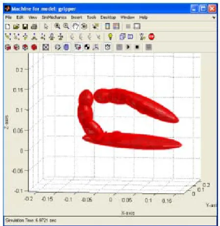
Fig. 12. Position of gripper at the end of 6.9721 sec
[image:6.595.53.278.318.753.2]Graphical visualization of the motion of the gripper was also obtained. The graphs obtained are as shown below:
Fig. 13. Position of Reaction torque and force measurement at pin (long)-distal phalange joint
[image:6.595.309.545.356.705.2]displacement (mm) and linear acceleration (mm/ s2 ) in the x
direction (yellow coloured line) and z direction (blue coloured line). There is angular displacement (rad/s) i.e. rotation and angular acceleration (rad/s2 ) only about y axis
(violet coloured line).
VII. RESULTS AND DISCUSSIONS
Similarities are observed for the motion analysis completed using simulation packages and by experimentations. The output measurement graph shows that a linear displacement (mm) and linear acceleration (mm/s2 )
[image:7.595.52.286.227.549.2]in the x direction (yellow coloured line) is with more rapid in motion than and z direction (blue coloured line).
Fig. 14. Reaction torque and force measurement at pin (short)-distal phalange joint
VIII. CONCLUSIONS
The reaction force and reaction torque on the distal phalange at the joint of the pin (connecting link 3 and distal phalange) and the distal phalange can be measured. The reaction force and reaction torque on link 3 at the joint of the pin (connecting link 3 and distal phalange) and the link 3can be measured. This designed gripper is useful for grasping lightweight object with dexterous manipulation. By using interfacing circuits, programmable controls biomimetic approach can be inculcated to the grasping system. Dynamic simulation guides for analysis of various operational parameters such as real time controlling, better sequential moves…etc
ACKNOWLEDGMENT
Authors are thankful to Dr S K Basu and Dr P K Mishra, both professor emeritus College of Engineering, Pune for their continuous support and guidance towards completion of this work. Consistent support of colleagues from Mechanical Engineering Department, COE, Pune and active help of S. Parmar, P. Zambere, A. Ashtaputre of College of Engineering, Pune is equally credited.
REFERENCES
[1] Y. Zhang and W. A. Gruver, Classification of Grasps by Multifingered Robot Hands, IEEE/RSJ International Conference on Intelligent Robots and Systems, 1996.
[2] N. Xydas and I. Kao, Influence of Material Properties and Fingertip Size on the Power-Law Equation for Soft Fingers, IEEE/RSJ International Conference on Intelligent Robots and Systems, 2000. [3] L. Biagiotti, P. Tiezzi, G. Vassura and C. Melchiorri, Modelling and
Controlling the Compliance of a Robotic Hand with Soft Finger-pads, Springer Tracts in Advanced Robotics, 2005. IEEE International Conference on Robotics and Automation, Workshop on Multi-point Interaction in Robotics and Virtual Reality, New Orleans, LA. 2004. [4] L. Birglen, C. M. Gosselin, Kinetostatic Analysis of Underactuated
Fingers, IEEE Transactions on Robotics and Automation, Vol. 20, No. 2, April 2004.
[5] A. Ghafoor, J. S. Dai, J. Duffy, Stiffness Modeling of the Soft-finger Contact in Robotic Grasping. ASME Journal of Mechanical Design , Volume 126, Issue 4, pp. 646-656, July 2004.
[6] M. T. Das, L. C. Dülger, Mathematical Modeling, Simulation and Experimental Verification of a SCARA Robot, Science Direct, Volume 13, Issue 3, April 2005.
[7] G.B. Madhab, C.S. Kumar, P.K. Mishra, Modeling and Control of Flexure-based Miniature Robotic End-effector, First International & 22ND All India Manufacturing Technology Design & Research Conference, IIT Roorkee, December 2006.