Geosci. Instrum. Method. Data Syst., 2, 213–224, 2013 www.geosci-instrum-method-data-syst.net/2/213/2013/ doi:10.5194/gi-2-213-2013
© Author(s) 2013. CC Attribution 3.0 License.
EGU Journal Logos (RGB)
Advances in
Geosciences
Open Access
Natural Hazards
and Earth System
Sciences
Open Access
Annales
Geophysicae
Open Access
Nonlinear Processes
in Geophysics
Open Access
Atmospheric
Chemistry
and Physics
Open Access
Atmospheric
Chemistry
and Physics
Open Access
Discussions
Atmospheric
Measurement
Techniques
Open Access
Atmospheric
Measurement
Techniques
Open Access
Discussions
Biogeosciences
Open Access Open Access
Biogeosciences
Discussions
Climate
of the Past
Open Access Open Access
Climate
of the Past
Discussions
Earth System
Dynamics
Open Access Open Access
Earth System
Dynamics
Discussions
Geoscientific
Instrumentation
Methods and
Data Systems
Open Access
Geoscientific
Instrumentation
Methods and
Data Systems
Open Access
Discussions
Geoscientific
Model Development
Open Access Open Access
Geoscientific
Model Development
Discussions
Hydrology and
Earth System
Sciences
Open Access
Hydrology and
Earth System
Sciences
Open Access
Discussions
Ocean Science
Open Access Open Access
Ocean Science
Discussions
Solid Earth
Open Access Open Access
Solid Earth
Discussions
The Cryosphere
Open Access Open Access
The Cryosphere
Discussions
Natural Hazards
and Earth System
Sciences
Open Access
Discussions
A radiation hardened digital fluxgate magnetometer
for space applications
D. M. Miles1, J. R. Bennest2, I. R. Mann1, and D. K. Millling1
1Department of Physics, University of Alberta, Edmonton, Alberta, T6G 2E1, Canada 2Bennest Enterprises Ltd, Summerland, British Columbia, V0H 1Z0, Canada
Correspondence to: D. M. Miles ([email protected])
Received: 5 February 2013 – Published in Geosci. Instrum. Method. Data Syst. Discuss.: 20 February 2013 Revised: 30 July 2013 – Accepted: 28 August 2013 – Published: 13 September 2013
Abstract. Space-based measurements of Earth’s magnetic
field are required to understand the plasma processes re-sponsible for energising particles in the Van Allen radiation belts and influencing space weather. This paper describes a prototype fluxgate magnetometer instrument developed for the proposed Canadian Space Agency’s (CSA) Outer Radia-tion Belt InjecRadia-tion, Transport, AcceleraRadia-tion and Loss Satellite (ORBITALS) mission and which has applications in other space and suborbital applications. The magnetometer is de-signed to survive and operate in the harsh environment of Earth’s radiation belts and measure low-frequency magnetic waves, the magnetic signatures of current systems, and the static background magnetic field. The new instrument offers improved science data compared to its predecessors through two key design changes: direct digitisation of the sensor and digital feedback from two cascaded pulse-width modulators combined with analog temperature compensation. These pro-vide an increase in measurement bandwidth up to 450 Hz with the potential to extend to at least 1500 Hz. The in-strument can resolve 8 pT on a 65 000 nT field with a mag-netic noise of less than 10 pT/
√
Hz at 1 Hz. This performance is comparable with other recent digital fluxgates for space applications, most of which use some form of sigma-delta (61) modulation for feedback and omit analog tempera-ture compensation. The prototype instrument was success-fully tested and calibrated at the Natural Resources Canada Geomagnetics Laboratory.
1 Introduction and application
Space-based measurements of Earth’s magnetic field are re-quired to understand the plasma processes underlying the solar–terrestrial connection. This includes the nature of the current systems and plasma waves during storms and sub-storms which are thought to cause acceleration and loss of energetic particles in the Van Allen radiation belts, and which constitute space weather. This paper describes a radia-tion hardened fluxgate magnetometer developed for the pro-posed Canadian Space Agency’s (CSA) Outer Radiation Belt Injection, Transport, Acceleration and Loss Satellite (OR-BITALS) mission (Mann et al., 2006).
The base fluxgate design used in this prototype has more than two decades of terrestrial heritage in the Canadian and American CARISMA/CANOPUS (Mann et al., 2008), POLARIS (Eaton et al., 2005), and EMScope/EarthScope USArray (Schultz, 2009) instruments built by Narod Geo-physics Ltd (NGL) (e.g. Narod and Bennest, 1990). The NGL design was previously modified for low-radiation space applications as the magnetic field instrument (MGF) in the CSA’s enhanced Polar Outflow Probe (ePOP) payload on the CAScade, Smallsat and IOnospheric Polar Explorer (CAS-SIOPE) satellite (Wallis et al., 2006).
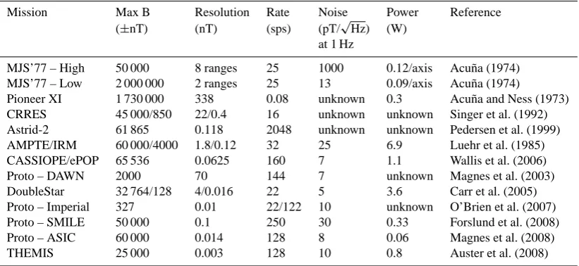
Table 1. Performance characteristics of relevant recent and historical spaceflight fluxgate magnetometers.
Mission Max B Resolution Rate Noise Power Reference (±nT) (nT) (sps) (pT/
√
Hz) (W) at 1 Hz
MJS’77 – High 50 000 8 ranges 25 1000 0.12/axis Acu˜na (1974) MJS’77 – Low 2 000 000 2 ranges 25 13 0.09/axis Acu˜na (1974)
Pioneer XI 1 730 000 338 0.08 unknown 0.3 Acu˜na and Ness (1973) CRRES 45 000/850 22/0.4 16 unknown unknown Singer et al. (1992) Astrid-2 61 865 0.118 2048 unknown unknown Pedersen et al. (1999) AMPTE/IRM 60 000/4000 1.8/0.12 32 25 6.9 Luehr et al. (1985) CASSIOPE/ePOP 65 536 0.0625 160 7 1.1 Wallis et al. (2006) Proto – DAWN 2000 70 144 7 unknown Magnes et al. (2003) DoubleStar 32 764/128 4/0.016 22 5 3.6 Carr et al. (2005) Proto – Imperial 327 0.01 22/122 10 unknown O’Brien et al. (2007) Proto – SMILE 50 000 0.1 250 30 0.33 Forslund et al. (2008) Proto – ASIC 60 000 0.014 128 8 0.06 Magnes et al. (2008) THEMIS 25 000 0.003 128 10 0.8 Auster et al. (2008)
application as a secondary science payload called as the Plasma and Radiation In Molniya Orbit (PRIMO) secondary science payload (Mann et al., 2011) on the CSA’s Polar Com-munications and Weather (PCW) satellite (Trishchenko and Garand, 2012).
For both missions, the fluxgate magnetometer was re-quired to measure the static magnetic field and magnetic waves at frequencies below 10 Hz. The static magnetic field measurements are required to understand the structure of the magnetospheric magnetic field, the role of current sys-tems, and the dynamical motion and wave-particle accelera-tion, transport, and loss of energetic particles. Ultra low fre-quency (ULF) magnetic waves are thought to interact with low-energy particle populations and accelerate them to form damaging, high energy (MeV) space radiation (e.g. Friedel et al., 2002). Wave–particle interactions are also believed to be responsible for scattering particles into the loss cone. This depletes the radiation belts and has potentially important consequences for the atmosphere and climate change (e.g. Sepp¨al¨a et al., 2007).
Current fluxgate sensor technology provides limited useful sensitivity at high (>10 to 100 Hz) frequencies compared to induction coil magnetometers. However, if future cores are available with substantially lower noise (e.g. Narod, 2013) then higher frequency fluxgate measurements would become increasingly useful. Also, in applications such as flights of opportunity on commercial satellites, it may not be possi-ble to fly both fluxgate and induction coil magnetometers. In this case, even lower sensitivity high frequency measure-ments may be useful.
The prototype instrument uses only electronic components which have space grade (Class S) equivalents that are radia-tion tolerant to at least 100 krad. This allows the instrument to be manufactured for space flight applications in a high radiation environment. The new instrument has a low parts
count and is not dependent on high-performance commercial components. This has been achieved by replacing much of the analog signal conditioning used in previous designs with equivalent digital processing in a field programmable gate array (FPGA).
The new design is simpler than its predecessors and of-fers improved science data through two key design improve-ments. Firstly, direct digitisation of the sensor removes the need for complex analog filtering of the fluxgate signal. Sec-ondly, a novel dual pulse width modulation design provides digital feedback while preserving the sensor temperature compensation found in classical analog fluxgate magnetome-ters. These two changes provide bandwidth up to 450 Hz with the potential to extend to at least 1500 Hz in future work. This paper describes the instrument improvements, the key subsystems, and the performance of the resulting prototype instrument.
2 Modern state of space fluxgate magnetometers
The new fluxgate magnetometer design for the ORBITALS application was designed to meet the mission’s science re-quirements and survive the expected harsh radiation envi-ronment of the Van Allen radiation belts. The prototype de-scribed in this paper meets these requirements and is an in-terim step towards a fully modernised radiation hardened digital instrument. Table 1 summarises the key performance metrics of recent and historical fluxgate magnetometers de-signed for space applications.
The MGF instrument from the CSA’s ePOP payload (Wallis et al., 2006) is the design on which this prototype is based but is not sufficiently radiation tolerant for the OR-BITALS mission.
resulting prototype has limited range and does not actively temperature compensate the sensor.
NASA’s THEMIS fluxgate magnetometer (Auster et al., 2008) is a recently deployed, and highly successful, space-flight instrument. However, the THEMIS instrument uses component level embedded shielding which is not consid-ered acceptable in the harsh radiation environment of the OR-BITALS mission. This approach to radiation mitigation tends to have geometric vulnerabilities (e.g. vulnerable to omnidi-rectional radiation). The ORBITALS mission has long dwells in the highly energetic radiation belts and forbid the use of this type of radiation mitigation. ORBITALS planned to use 7 mm of Al shielding at the instrument level, so radiation reaching the components is necessarily highly penetrating and is not effectively stopped by the integrated shielding.
SMILES (Forslund et al., 2008) is a miniaturised digi-tal fluxgate magnetometer designed for small spacecraft ap-plications. This design uses a sophisticated hybrid of pulse width modulation (PWM) and sigma-delta (61) modulation to provide digital feedback. The hybrid design seeks to bal-ance the excellent linearity of a PWM with the higher usable bandwidth of61modulation. The feedback itself is not tem-perature compensated, rather the temtem-perature of the sensor is measured for post-processed compensation. The prototype has outstanding mass and volume characteristics; however, it relies on commercial off-the-shelf components which are not suitable for use in the radiation belts.
Magnes et al. (2008) describe a highly integrated front-end for a spaceborne fluxgate. The design is very compact, low power and has an excellent parametric radiation tolerance of 170 krad (300 krad functional). The front-end is implemented in a custom hybrid analog/digital application specific inte-grated circuit (ASIC). The design merges a second order61
modulator with a conventional analog fluxgate control loop. The design uses a resistor for feedback current translation and achieves excellent drift and temperature characteristics.
The prototype described in this paper implements a new digital feedback topology using two cascaded PWMs com-bined with classical analog temperature compensation of the feedback circuit. This design has lower complexity than many of the state-of-the art instruments and can be con-structed from highly radiation tolerant parts. This simplicity is at the expense of being larger, less integrated, and con-suming more power. The cascaded PWMs have the potential for non-linearity depending on the precision of the mixing network.
3 Instrument design
The instrument described in this paper is a redesign and further radiation hardened development of the CAS-SIOPE/ePOP fluxgate magnetometer instrument (MGF); analog signal conditioning circuitry was replaced with digital processing in an FPGA to mitigate radiation and temperature
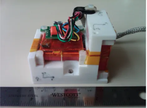
Fig. 1. Fluxgate sensor used in the prototype instrument. This
hard-ware is the CASSIOPE/ePOP MGF engineering model with minor modifications.
effects. The prototype uses a modified version of the flight-spare fluxgate sensor from the CASSIOPE/ePOP with two low-noise Infinetics ring cores (Fig. 1). This sensor uses the established technique (e.g. Acu˜na and Pellerin, 1969) of dou-ble winding a ring core to sense two components of the mag-netic field using one ring core.
The ePOP MGF electronics were designed such that the noise floor of the overall instrument was set by the intrinsic noise of the two ring cores in the sensor. One of the goals for the new prototype instrument was to achieve the same noise floor of less than 10 pT/
√
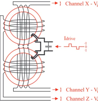
Hz root mean square (RMS) at 1 Hz as was achieved by the CASSIOPE/ePOP fluxgate but in a radiation hard, digital, and temperature compensated design. As in the MGF instrument sensor, theXandY components are derived from a single sense winding on each core while the Z component is derived from sense windings on each sensor core connected in series (see Fig. 2). The two dual-wound sensor bobbins are mounted on a block of MACOR machinable ceramic to minimise sensitivity changes due to temperature variation.
Idrive
Channel X - Vi }
Channel Y - Vi
}
Channel Z - Vi
}
I I
+ -0
Fig. 2. Schematic wiring of theX,Y, andZsensor components and
the drive winding in the prototype.XandY are single windings whileZis derived from two windings in series. Note that the two ring cores are physically orthogonal as shown in Fig. 1.
converter (ADC) to become the input to a control loop imple-mented in the FPGA. The output of the control loop is sent to the digital-to-analog converter (DAC) and converted into a precise, temperature compensated current (V/I). This nega-tive feedback drives each component of the magnetic field in the sensor head towards zero.
Figure 4 shows a block diagram of the major elements of the FPGA logic. Variablesk0,k1,k2, andk3are
experimen-tally determined scaling coefficients for the coarse PWM, fine PWM, ADC, and offset respectively. The ADC value used to compute the final datum is the arithmetic mean of 64 ADC samples. Averaging over an even number of ADC reading and subtracting an experimentally determined con-stant removes the static offset which would otherwise result from the coupling of the drive winding to the sense winding.
3.1 Direct digitisation
The bandpass filters and analog integrators traditionally used in second harmonic fluxgate magnetometers (e.g. Narod and Bennest, 1990) to sense the fluxgate signal at twice the sensor drive frequency (2f) are not required in this design. In the prototype, the sensor is directly digitised by sampling the in-stantaneous output from the sensor. In a classical design, the sensor is bandpass filtered, and integrated using analog pro-cessing before the signal is digitised. The direct digitisation approach can be described using the standard fluxgate induc-tion equainduc-tion (Ripka, 2001) which relates the sensor voltage
Vi to the static magneticH field through the modulation of
the relative permeabilityµrof the sensor core:
Vi =(N A µ0H)
dµr
dt . (1)
I
feedbackIdrive
Hsense
PA
I/V ADC FPGA
DAC
I
feedbackI
senseI I + -0 V/I
Fig. 3. Schematic of one fluxgate component showing the major
components. The FPGA controller generates a 28 800 Hz drive sig-nal that is power amplified (PA) and sent into the drive winding to periodically saturate and and unsaturate the ring cores. The band-pass, phase synchronous detector, low band-pass, and integrator hard-ware in a classic 2f fluxgate are replaced with a current-to-voltage converter (I/V) and an ADC to digitise the signal. An FPGA uses the fluxgate signal as the input to a control loop to drive the mag-netic field in the sensor towards zero. The output of the control loop is converted to an analog signal (DAC) and then to a high-precision, temperature compensated current to provide magnetic feedback (V/I).
ADC
Sample 0}
Sample 1 ... Sample 63mean
Proportional
Controller
Setpoint = 0
Fine
Feedback
Coarse
Feedback
if (FinePWM > 7/8 Fullscale) or (FinePWM < 1/8 Fullscale)
PWM
PWM
Output Datum
= k0* CoarsePWM + k1* FinePWM + k2* ADC + k3
Fig. 4. Block diagram showing major elements of the FPGA logic.
Variablesk0, k1, k2, andk3are experimentally determined
scal-ing coefficients for the coarse PWM, fine PWM, ADC, and offset respectively.
-+
Isense
Iinput
Iout
Vout
DACI
feedback ADCC
1C2
R
1 V/IFig. 5. Equivalent circuit of the sensor preamplifier in the prototype
instrument.
coil response by suppressing this self resonance. The voltage across the coil is forced to zero by the short circuit; however, there is still a circulating current determined by Ohm’s law whereVi is the unloaded coil voltage.
Isense=
Vi
Rwinding
(2) Substituting the fluxgate induction equation from Eq. (1) gives
Isense=
(N A µ0H)dµdtr
Rwinding
. (3)
The operational amplifier is configured as a transimpedance amplifier (current-to-voltage converter) and is selected to be approximated by the ideal amplifier assumptions (zero input current, zero offset, arbitrarily large gain). As the net current at the inverting input must be zero, Kirchhoff’s current law analysis at the inverting amplifier input shows that
Inet =Isense+Iinput+Iout=0. (4)
The input current to the amplifier is essentially zero
(Iinput= 0). The capacitorC1is selected such that it passes
the second harmonic AC fluxgate signal but blocks the quasi-static signal from the feedback DAC soIfeedback= 0 at theb
frequency (twice the drive frequency,f).C2keeps the
am-plifier from oscillating and suppresses high frequency noise but doesn’t pass significant current at the 2f frequency.Iout
can be re-written using Ohm’s law (Iout=Vout/R1). Making
these substitutions gives
0=Isense+Iinput+Iout+Ifeedback, (5)
0=Isense+0+
Vout
R1
+0, (6)
Vout= −R1·Isense. (7)
Isense from the fluxgate sensor is balanced by Iout from
the amplifier feedback. Finally, substitution forIsense using
Eq. (3) gives
Vout= −
R1
Rwinding
N A µ0H
dµr
dt . (8)
-5 0 5 B = + 24 ,8 20 n T -5 0 5 B = + 74 0 nT -5 0 5 B = -7 0 nT -5 0 5 B = -8 70 n T
0 10 20 30 40 50 60
-5 0 5 B = -2 4, 43 0 nT Time (µs) V ou t (V ) V ou t (V ) V ou t (V ) V ou t (V ) V ou t (V ) (a) (b) (c) (d) (e)
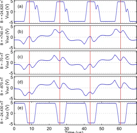
Fig. 6. Vout at various applied magnetic fields that are (a) large
positive (+24 820±10 nT), (b) small positive (+740±10 nT),
(c) near zero (−70±10 nT), (d) small negative (−870±10 nT),
and (e) large negative (−24 430±10 nT).
When the drive winding is modulating the relative permeabil-ity of the sensor (dµr
dt 6=0) the preamplifier produces a voltage Vout. This voltage is proportional to the instantaneous
mag-neticH field, has configurable gain via resistorR1, and
pro-vides a low-impedance output which can be digitised without loading the sensor and distorting the signal.
TheVoutsignal is composed of even harmonics of the dµdtr
fluxgate action frequency at 2f, 4f, etc. and the transformer coupled harmonics of the drive signal atf, 2f, etc. The flux-gate action will causeVoutto pulse at 2f in proportion to the
strength of the local magnetic field. However, these pulses will be superimposed on the constant, phase locked residual harmonics of the drive signal.
Figure 6 shows a time series of Vout under test
con-ditions using applied external magnetic fields which are (a) large positive (+24 820±10 nT), (b) small positive (+740±10 nT), (c) near zero (−70±10 nT), (d) small negative (−870±10 nT), and (e) large negative (−24 430±10 nT). Panels a and e are saturated due to maxi-mum amplifier output compliance and do not correspond the external magnetic field beyond indicting out-of-range high and low respectively. However, in the operating instrument the digital feedback would quickly return the field within the sensor back into the unsaturated region.
in Fig. 6 show the times when the ADC samplesVout, phase
locked to the 2f signal effectively creating a synchronous detector. The irregularity on the decreasing slope in Fig. 6a (+24 820±10 nT) varies by axis and individual sensor. It is believed to be related to asymmetries in the sensor core.
The amplitude of the 2f pulses, as measured at the ADC trigger points, tracks the applied magnetic field in amplitude and polarity. However, even in a near zero field (Fig. 6c,
−70±10 nT), there is a residual AC signal from the drive current primarily atf and 2f. The ADC measurements must be averaged over an even number of samples to cancel the harmonics.
Digitising the signal directly at the ADC trigger points re-quires minimal analog processing and is not subject to tem-perature effects common to analog filters. However, since the signal has not been bandpass filtered around the 2f fre-quency, low frequency fluctuation of the amplifier and theddtH action of the sensor will be added to the fluxgate signal. This represents a potential source for both noise and zero offset temperature dependence.
It is important to note that even in a strong field (Fig. 6a,
+24 820±10 nT and Fig. 6e,−24 430±10 nT) the ampli-tude of the error signal at the ADC trigger points is mono-tonic and strictly increasing with magnetic field. This is es-sential to the control system because any local extrema or out-of-range polarity inversion would cause the control loop to apply feedback in the wrong direction and cause the in-strument to oscillate or become stuck and full at positive or negative full scale. Signal inversion can be possible with certain amplifiers with large signals such that the inputs or outputs approach the supply voltages. This would not be a problem during normal operation with the digital feedback enabled but could interfere with the initial servo to the in-strument’s operating point when initially turned on in a field large enough to clip the analog system.
3.2 Analog-to-digital converter oversampling
The digital feedback is always trying to drive the field in the sensor to zero so the output of the sensor is both a partial measurement of the field and the instantaneous error in the digital feedback value. The sensor output is therefore referred to as the “error signal” to be consistent with control system nomenclature.
The prototype instrument is designed such that the analog-to-digital converter has a least significant bit of 57 pT. This is the smallest resolution which can accommodate the analog error signal under normal operating conditions. However, the error signal is digitised at 57 600 sps and decimated by 64 into a 900 sps (samples per second) data product. Oversam-pling by four times can create one effective bit of resolution. Therefore, oversampling byN= 64 = 43 creates three addi-tional bits of resolution for an effective resolution of
Physical Resolution 2
logN log 4
=
57 pT 23
=
7.1 pT
(9)
or, to the next largest integer, 8 pT resolution.
In the current prototype the 57 600 sps measurements are simply decimated into the final data product. This makes the prototype vulnerable to aliasing effects from out-of-band sig-nals. In future work a digital antialiasing filter will be added to mitigate this.
3.3 Temperature compensated digital feedback
In this instrument, the PWM based DAC changes its average output by varying the duty cycle of a pulse train emitted at a fixed repetition rate. A subsequent low-pass filter (LPF) attenuates the repetition-rate frequency, and its harmonics, leaving only the average value. The simplest possible PWM based DAC feedback system has three components.
1. A single-pole, double-throw (SPDT) break-before-make transmission-gate switch (sourced from precision bipolar reference voltages) to create a variable duty cy-cle pulse train.
2. A low-pass filter to remove the switching frequency. 3. A voltage-to-current converter to drive the feedback
coil.
Some digital fluxgate magnetometers (e.g. O’Brien et al., 2007) use a simple resistor–capacitor low-pass filter to drive the digital pulse train into the feedback coil using a resis-tor for current conversion. To first order, the resisresis-tor acts as a voltage-to-current converter and the average feedback cur-rent experienced by the sensor is the same.
However, a simple resistor is not a controlled current source and cannot be used to provide temperature compen-sation for the sensor. The geometry of the sensor’s feedback winding will change slightly with temperature primarily due to variation in coil length and circumference. As a conse-quence, the amount of magnetic feedback for a given current varies with temperature. Primdahl (1970) and then Acu˜na et al. (1978) describe a technique for temperature compensa-tion by noting that the resistance of the coil also changes with temperature and that these two effects can be used to cancel each other.
digital designs. The technique requires a low-pass recon-struction filter on the digital feedback to avoid clipping the transconductance feedback amplifier with the comparatively large switching signal from the PWM. The design outlined below can be constructed from radiation hardened compo-nents and implements high resolution digital feedback while preserving the temperature compensation of the fluxgate sensor.
The feedback frequency range should generally be wide enough to include the sampling frequency to make the feed-back control loop robust and stable. The prototype instru-ment measures each axis at 900 sps (samples per second). The PWM repetition rate was set a decade higher to allow a 3-pole low-pass reconstruction filter with−3 dB corner near 1 kHz to provide greater than 60 dB attenuation of the PWM repetition frequency. This leaves a residual PWM amplitude small enough to avoid saturating the feedback amplifier. The repetition rate of the PWM was set to 14 400 Hz (the next di-visor of the common clock frequency) to ensure that the feed-back is locked in phase with the other instrument functions.
The magnetic range of the instrument was set to
±65 536 nT to cover the expected geomagnetic field experi-enced in ground and space applications. A resolution of 8 pT was selected in anticipation of ultra-low-noise cores which may result from the ongoing research (e.g. Narod, 2013).
Resolving 8 pT within this range requires 24 bit resolu-tion. The best available radiation hard ADC (the RAD1419) can provide 14 bits of resolution. Even in a constant field, the value of two successive ADC values can vary by more than half the±2.5 V total ADC input range due to the sig-nificant residual of the sensor drive signal. If the input value is too large or too small then the half of the samples will be clipped and invalid. This restricts the accurately usable input range of the ADC and costs two bits for an effective 12 bits of resolution. This requires the remaining 12 bits of resolution to be supplied by the digital-to-analog converter in the feed-back network. Note that although only 12 bits of resolution are required, the digital-to-analog converter must be quiet at the 24 bit level in the frequency range of the instrument to avoid being the dominant noise source in the error signal. In a PWM based digital-to-analog converter, this primarily in-volves suppressing the PWM repetition rate below the 24 bit level in the final data product.
The base frequency required for a simple PWM to deliver this would be
14 400 Hz×212 =58 982 400 Hz≈60 MHz. (10) This is significantly faster than the best available radiation hardened analog switches (Intersil part HS303ARH) which, in this prototype, started to have marginal performance at 20 MHz.
Figure 7 shows a functional diagram of a dual PWM feed-back network which solves this problem. Each 10 bit PWM sets its output level by the duty cycle of the pulse train. The low-pass filter reduces the amplitude of the 14 400 Hz PWM
FINE PWM
Vpwm LPF SCALING
1/256
+
COARSE PWM
Vpwm LPF
V/IIfeedback Vfeedback
PA and temperature
compensation
Fig. 7. Block diagram of the dual pulse width modulation feedback
network of the prototype instrument. The output is built up from two 10 bit PWMs at 14 400 Hz and low-pass filtered at 1 kHz. The two PWMs are scaled to overlap by two bits, summed, and con-verted into a feedback current using an intentionally mis-balanced transconductance amplifier to temperature compensate the feedback coil.
signal. The voltage of the fine PWM is attenuated to set its scaling compared to the coarse PWM and provide two bits of overlap for the control system. The fine PWM is then summed with the coarse PWM to create a voltage that can be set with a 10+10−2 = 18 bit resolution albeit with im-perfect linearity as determined by the accuracy of the mixing network.
Ultra-high stability, ultra-low temperature coefficient bulk foil resistors are used in the attenuator, summing network, and the transconductance amplifier feedback networks. Com-bining two digital-to-analog converters can introduce non-linear output. This effect is minimised by using resistors which are vendor trimmed to 0.01 % accuracy. Both PWMs are continuously mixed to create the feedback value. This leads to a short transient ripple if, for example, the coarse and fine PWMs each make an equal but opposite adjustment. Although the nominal total feedback remains constant, the two changes in duty cycle take slightly different times to set-tle through the mixing and filter network resulting in a short transient in the feedback experienced by the fluxgate sensor. The low-pass reconstruction filters do not completely sup-press the 14 400 Hz repetition rate. However, the amplitude is small enough that a classical analog transconductance power amplifier can be used to convert the voltage output into a tem-perature compensated current source. This approach allows a radiation hardened implementation of both digital feedback and sensor temperature compensation.
4 Potential for high frequency measurements
was tentatively attributed to the synchronous detector rather than the sensor or the fluxgate action.
Primdahl’s results, and the fact that there is no obvious physical reason why the fluxgate action should decay with frequency, suggests that the AC response of the prototype in-strument should be explored. The repetition rate of the feed-back PWMs limits the prototype instrument to 900 sps or 450 Hz Nyquist. Testing the performance of the instrument above this frequency therefore required probing the analog preamplifier signal directly.
The feedback network of the instrument was temporar-ily disabled by fixing both the coarse and fine PWM at mid range. In this configuration, the error signal from the pream-plifier is analogous to a standard amplitude modulated sinu-soidal signal (cf. AM radio). The 2f signal replaces the car-rier (frequencyωc, amplitudeAc) and the applied magnetic
field acts as the modulating signal (frequencyωm, amplitude Am). The result is a time series of the form:
y(t )=Ac×sin(ωct )+ Am
2 [sin(ωc+ωm) t+sin(ωc−ωm) t].(11)
This analogy allows us to visualise the fluxgate action di-rectly by sampling the error signal with a bench-top spectrum analyser. The 2f carrier frequency shows as a spectral fea-ture at 57 600 Hz whose amplitude is dependent on the static field strength. However, an applied AC test signal will appear as two sideband carriers at 57 600 Hz plus or minus the AC signal frequency. The panels in Fig. 8 show, from top to bot-tom, the resulting spectral plots for no test signal, 100, 200, 500, 1000, and 1500 Hz. Note that the amplitude of the side-band carriers is essentially constant with frequency increas-ing slightly at 1500 Hz and there are no other large amplitude features within 57 600±1500 Hz. This suggests that, if the PWM frequency and sampling frequency were increased, the prototype fluxgate should provide data up to at least 1500 Hz.
5 Instrument performance
5.1 Test set-up
Magnetic noise and RMS error analysis were conducted at the National Resources Canada Geomagnetics (NRCan) Laboratory on Anderson Rd, Ottawa, ON, Canada. The Building 8 facility contains a calibrated reference source, a three-axis Helmholtz coil, and an observatory grade magne-tometer to cancel local geomagnetic variations. This provides a magnetically quiet location suitable for the long-period measurements required to characterise the low-frequency noise floor of the instrument.
Instrument resolution and AC performance were com-pleted at the University of Alberta CARISMA laboratory in Edmonton, AB, Canada. The fluxgate sensor was placed in a test solenoid within a three layer magnetic shield. The test signals were generated by driving the solenoid with a Stanford Research DS360 ultra low distortion function
generator. This facility has significantly more magnetic noise than the NRCan facility (nearby elevator, large compressor for a walk-in freezer, and overhead air-conditioning and ven-tilation fans) which make noise measurements, particularly at low frequencies, difficult compared to the NRCan facil-ities. The test solenoid and signal generator are not cali-brated against an established magnetic reference. However, the CARISMA laboratory test fixture was developed for test-ing induction coil magnetometers and is ideal for testtest-ing the dynamic performance of the prototype fluxgate.
5.2 Magnetic resolution
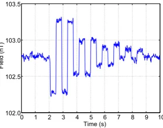
The magnetic resolution of the coupled fluxgate sensor and electronics were validated using test signals applied by a solenoid within a three layer magnetic shield. Figure 9 shows a time series of two cycles, each of square waves at ampli-tudes of 1, 0.5, 0.25, and 0.125 nT respectively. Data is post-processed with a 1 Hz low-pass filter to remove environmen-tal 60 Hz noise.
Figures 10 and 11 show amplitude spectra resolving 18 pT RMS (50 pT peak-to-peak) sine-wave test signals at 1 and 400 Hz, respectively. An 18 pT RMS test signal, rather than 8 pT RMS, was used such that the contribution of the noise floor to the spectral amplitude measurement was negligible. The narrow spectral features near 11, 55, and 60 Hz are be-lieved to be environmental. The broad, low amplitude feature around 100–200 Hz is dependent on the DC power supply used and is believed to be instrumental due to poor power supply noise rejection.
The effective noise bandwidth (ENBW) value shown in the Figs. 10 and 11 is the scaling factor, as defined by Heinzel et al. (2002), allowing the presented amplitude spectra to be converted into power spectral density via
Amplitude Spectrum=pPower Spectral Density×ENBW.(12)
5.3 Instrument noise floor
Figure 12 shows a long-period average power spectral den-sity plot taken in the magnetically quiet NRCan environment. The prototype instrument resolves the the sub-10 pT/
√
Hz RMS at 1 Hz noise of the sensor core and is consistent with the previous CASSIOPE ePOP MGF results. Significantly, the new digital design achieves the same noise floor and bet-ter resolution while providing 900 sps compared to 160 sps in the previous design. The double-peaked noise feature be-tween 200 and 300 Hz is again believed to be related to the power converter and will be addressed in the next revision of hardware.
5.4 Electronics noise floor
-100-80 -60 -40 -200
No Signal
Amplitude (dB)
-100-80 -60 -40 -200
10
0
H
z S
ig
na
l
Amplitude (dB)
-100-80 -60 -40 -200
20
0
H
z S
ig
na
l
Amplitude (dB)
-100-80 -60 -40 -20 0
50
0
H
z S
ig
na
l
Amplitude (dB)
-100-80 -60 -40 -20 0
1,
00
0
H
z S
ig
na
l
Amplitude (dB)
56.00 56.25 56.50 56.75 57.00 57.25 57.50 57.75 58.00 58.25 58.50 58.75 59.00 59.50 55.50 -100
-80 -60 -40 -20 0
1,
50
0
H
z S
ig
na
l
Amplitude (dB)
Frequency (kHz)
Fig. 8. Spectral analysis of the directly sampled error signal showing the modulation of the 2f major carrier sidebands by applied sinusoidal
magnetic signals up to 1500 Hz.
0 1 2 3 4 5 6 7 8 9 10 102.0
102.5 103.0 103.5
Fi
el
d
(n
T)
Time (s)
Fig. 9. Time series showing two cycles, each of square waves
at amplitudes of 1, 0.5, 0.25, and 0.125 nT respectively. Data is post-processed with a 1 Hz low-pass filter to remove environmen-tal 60 Hz noise.
digital-to-analog converter and the analog-to-digital con-verter is well below that measured with the fluxgate sensor in circuit.
5.5 RMS error
To quantify the RMS error, the sensor was placed within a known field generated by the Helmholtz coil test equipment
10−1 100 101 102
10−4 10−3 10−2 10−1 100
Frequency (Hz)
Amplitude (nT RMS)
x − nT RMS
Fig. 10. Amplitude spectrum showing resolution of prototype
in-strument. Arrow shows an 18 pT RMS sinusoidal test signal at 1 Hz.
at NRCan. Each component was varied over the full-scale range and compared to a measurement of the current used to drive the Helmholtz coil.
10−1 100 101 102 10−4
10−3 10−2 10−1 100
Frequency (Hz)
Amplitude (nT RMS)
x − nT RMS
Fig. 11. Amplitude spectrum showing resolution of prototype
in-strument. Arrow shows an 18 pT RMS sinusoidal test signal at 400 Hz.
10−1 100 101 102
10−4
10−3
Frequency (Hz)
Power Spectral Density (nT
2/Hz)
Z − PSD 10pT/rootHz 7pT/rootHz 5pT/rootHz
Fig. 12. Power spectral density noise floor of the prototype
instrument.
measurements. The difference between each measured point and the ideal measurement are then averaged by a RMS cal-culation following the equation
RMS Deviation= v u u u t
n
P
i=1
(Idealn−Actualn)2
n . (13)
Each datum is taken as the arithmetic mean of 900 samples (1 s) to cancel out the 60 Hz contamination. These analy-ses indicate that the prototype has an RMS error of 6.5 nT (Xcomponent), 6.4 nT (Y component) and 5.5 nT (Z com-ponent) RMS per point. This is equivalent to
7 nT
±65 536 nT =0.00005 (14)
or 0.005 % of full scale which meets the mission requirement of 0.1 %.
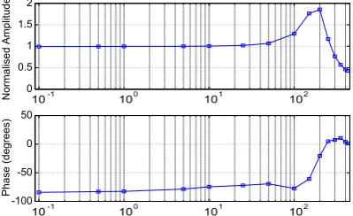
5.6 Frequency response
Figure 14 shows the amplitude and phase frequency response of the instrument. Note the peak in amplitude response
10-1 100 101 102
10-7
10-6
10-5
10-4
10-3
Frequency (Hz)
Power Spectral Density (nT
2 /Hz)
ENBW = 0.082397
Z - PSD 10pT/rootHz 7pT/rootHz 5pT/rootHz
Fig. 13. Power spectral density noise floor of the electronics with
the fluxgate sensor out of circuit.
0 0.5 1 1.5 2
N
orm
al
is
ed
Am
pl
itu
de
10-1 100 101 102
-100 -50 0 50
Ph
as
e
(d
eg
re
es
)
10-1 100 101 102
Fig. 14. Amplitude and phase frequency response of the prototype.
around 200 Hz and the phase shift starting at about 100 Hz. Several factors influence this including the three-pole low-pass filter in the feedback loop, the non-zero pickup of the
dH
dt action of the sensor, and the vulnerability to aliasing due
to the absence of a bandpass filter at 2f.
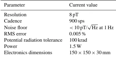
5.7 Performance summary
The key performance parameters of the prototype instrument are summarised in Table 2.
6 Future work
Table 2. Performance summary of the prototype instrument.
Parameter Current value Resolution 8 pT Cadence 900 sps Noise floor <10 pT/
√
Hz at 1 Hz RMS error 0.005 %
Potential radiation tolerance 100 krad
Power 1.5 W
Electronics dimensions 150×150×30 mm
feature between 100 and 300 Hz seen in the amplitude and power spectral density plots. Long-term drift tests and offset stability tests versus varying sensor and electronics tempera-tures will also be completed. A faster analog switch or a third PWM on each component will be added to increase the speed of the digital feedback loop and the bandwidth of the instru-ment. Faster digital feedback may also require a more so-phisticated control algorithm to allow the instrument to track very high slew rates such as those found on spinning sound-ing rocket applications which can be on the order of 5 Hz.
The prototype instrument is currently part of a proposed secondary plasma science payload on Canada’s flagship Po-lar Communication and Weather (PCW) satellite constella-tion (Trishchenko and Garand, 2012). The instrument is also expected to be flown as a Canadian contribution to the fourth Norwegian Investigation of Cusp Irregularities (ICI-4) sub-orbital sounding rocket mission (Moen et al., 2003).
7 Conclusions
The prototype instrument delivers 8 pT resolution in a
±65 536 nT field at 900 sps with a magnetic noise of less than 10 pT/
√
Hz RMS at 1 Hz. The magnetometer is designed to be radiation tolerant to 100 krad and to be entirely con-structed from space grade (Class S) parts so that it can be deployed in extreme radiation environments such as Earth’s radiation belts. The instrument uses a novel digital feedback process to improve the sampling rate and resolution while reducing complexity, parts count, and physical size. Signif-icantly, the novel magnetic feedback design combines digi-tal feedback with classic analog temperature compensation. This has produced a prototype modern, digital fluxgate mag-netometer suitable for a variety of ground, suborbital, and space applications.
Acknowledgements. This paper describes the improvement, extension and modernisation of an instrument design developed by Magnametrics, Narod Geophysics Ltd, and Bennest Enter-prises Ltd for the CASSIOPE/ePOP satellite. The University of Alberta, Department of Physics Electronics Shop provided significant assistance with the digital electronics. The authors would like to acknowledge the assistance of David Barona,
Bill Burris, Miroslaw Ciurzynski, Paul Davis, Alex Degeling, Andy Kale, Shengli Liu, Kyle Murphy, Barry Narod, Louis Ozeke, Jonathan Rae, Don Wallis, and Clare Watt. Instrument development was undertaken with the financial support of the Canadian Space Agency. I. R. Mann is supported by a Discovery Grant from the Canadian NSERC. The authors would like to thank Natural Resources Canada for the use of the Geomagnetics Laboratory facilities and their assistance characterising and calibrating the instrument.
Edited by: H. Svedhem
References
Acu˜na, M. H.: Fluxgate magnetometers for outer planets explo-ration, IEEE T. Mag., 10, 519–523, 1974.
Acu˜na, M. H. and Ness, N. F.: The Pioneer XI high field fluxgate magnetometer, Technical report, Goddard Space Flight Center, Greenbelt, Maryland, USA, 1973.
Acu˜na, M. H. and Pellerin, C. J.: A miniature two-axis fluxgate magnetometer, IEEE T. Geosci. Electron., 7, 252–260, 1969. Acu˜na, M. H., Scearce, C. S., Seek, J., and Scheifele, J.: The
MAGSAT vector magnetometer: A precision fluxgate magne-tometer for the measurement of the geomagnetic field, Technical report, National Aeronautics and Space Administration, Goddard Space Flight Center, Greenbelt, Maryland, 1978.
Auster, H., Glassmeier, K., Magnes, W., Aydogar, O., Baumjohann, W., Constantinescu, D., Fischer, D., Fornacon, K., Georgescu, E., Harvey, P., Hillenmaier, O., Kroth, R., Ludlam, M., Narita, Y., and Nakamura, R.: The THEMIS Fluxgate Magnetometer, Space Sci. Rev., 141, 235, 2008.
Carr, C., Brown, P., Zhang, T. L., Gloag, J., Horbury, T., Lucek, E., Magnes, W., O’Brien, H., Oddy, T., Auster, U., Austin, P., Aydogar, O., Balogh, A., Baumjohann, W., Beek, T., Eichel-berger, H., Fornacon, K.-H., Georgescu, E., Glassmeier, K.-H., Ludlam, M., Nakamura, R., and Richter, I.: The Double Star magnetic field investigation: instrument design, performance and highlights of the first year’s observations, Ann. Geophys., 23, 2713–2732, doi:10.5194/angeo-23-2713-2005, 2005.
Eaton, D. W., Adams, J., Asudeh, I., Atkinson, G. M., Bostock, M. G., Cassidy, J. F., Ferguson, I. J., Samson, C., Snyder, D. B., Tiampo, K. F., and Unsworth, M. J.: Investigating Canada’s Lithosphere and earthquake hazards with portable arrays, EOS, 86, 169–173, 2005.
Forslund, A., Belyayev, S., Ivchenko, N., Olsson, G., Edberg, T., Marusenkov, A.: Miniaturized digital fluxgate magnetometer for small spacecraft applications, Measurement Sci. Technol., 19, 015202, doi:10.1088/0957-0233/19/1/015202, 2008.
Friedel, R. H. W., Reeves, G. D., and Obara, T.: Relativistic electron dynamics in the inner magnetosphere – A review, J. Atmos. Sol.-Terr. Phys., 64, 265–282, 2002.
Heinzel, G., Rudiger, A., and Schilling, R.: Spectrum and spec-tral density estimation by the discrete fourier transform (DFT), including a comprehensive list of window functions and some new flat-top windows, Technical report, Max-Planck-Institut fur Gravitationsphysik, Teilinstitut Hannover, 2002.
Magnes, W., Pierce, D., Valavanoglou, A., Means, J., Baumjo-hann, W., Russell, C. T., Schwingenschuh, K., and Graber, G.: A sigmadelta fluxgate magnetometer for space applications, Measurement Sci. Technol., 14, 1003–1012, doi:10.1088/0957-0233/14/7/314, 2003.
Magnes, W., Oberst, M., Valavanoglou, A., Hauer, H., Hagen, C., Jernej, I., Neubauer, H., Baumjohann, W., Pierce, D., Means, J., and Falkner, P.: Highly integrated front-end electronics for space-borne fluxgate sensors, Measurement Sci. Technol., 19, 115801, doi:10.1088/0957-0233/19/11/115801, 2008.
Mann, I. R., Balmain, K. G., Blake, J. B., Boteler, D., Bourdarie, S., Clemmons, J. H., Dent, Z. C., Degeling, A. W., Fedosejeves, R., Fennell, J. F., Fraser, B. J., Green, J. C., Jordanova, V. K., Kale, A., Kistler, L. M., Knudsen, D. J., Lessard, M. R., Loto’aniu, T. M., Milling, D. K., O’Brien, T. P., Onsager, T. G., Ozeke, L. G., Rae, I. J., Rankin, R., Reeves, G. D., Ridley, A. J., Sofko, G. J., Summers, D., Thomson, I., Thorne, R. M., Tsui, Y. Y., Unick, C., Vassiliadis, D., Wygant, J. R., and Yau, A. W.: The outer radiation belt injection, transport, acceleration and loss satel-lite (ORBITALS): A Canadian small satelsatel-lite mission for ILWS, Adv. Space Res., 38, 1838–1860, doi:10.1016/j.asr.2005.11.009, 2006.
Mann, I. R., Milling, D. K., Rae, I. J., Ozeke, L. O., Kale, A., Kale, Z., Murphy, K., Parent, A., Usanova, M., Pahud, D., Lee, E.-A., Amalraj, V., Wallis, D., Angelopoulos, V., Glassmeier, K.-H., Russell, C., Auster, H.-U., and Singer, H.: The upgraded CARISMA magnetometer array in the THEMIS era, Space Sci. Rev., 141, 413–451, doi:10.1007/s11214-008-9457-6, 2008. Mann, I. R., Rae, I. J., Ozeke, L. G., Miles, D. M., and Yau, A.
W.: Plasma and Radiation In Molniya Orbit (PRIMO) Science Objective and User’s Needs Definition Document, Technical re-port, Universities of Alberta and Calgary for the Canadian Space Agency, University of Alberta, Department of Physics, Edmon-ton, Canada, 2011.
Moen, J., Bekkeng, J. K., Pedersen, A., Aase, J. G., de Feraudy, H., Søraas, F., Blix, T. A., Lester, M., and Pryse, S. E.: ICI-1: a new sounding rocket concept to observe micro-scale physics in the cusp ionosphere, in: 16th ESA Symposium on European Rocket and Balloon Programmes and Related Research, 2–5 June 2003, Sankt Gallen, Switzerland, edited by: Warmbein, B., ESA Publi-cations Division SP 530, Noordwijk, 543–548, 2003.
Narod, B.: The origin of noise and hysteresis in permalloy ring-core fluxgate sensors, EGU General Assembly Conference Abstracts, vol. 15, p. 2357, 2013.
Narod, B. B. and Bennest, J. R.: Ring-core fluxgate magnetometers for use as observatory variometers, Phys. Earth Planet. Interior., 59, 23–28, doi:10.1016/0031-9201(90)90205-C, 1990.
O’Brien, H., Brown, P., Beek, T., Carr, C., Cupido, E., and Oddy, T.: A radiation tolerant digital fluxgate magnetometer, Meas. Sci. Technol., 18, 3645, doi:10.1088/0957-0233/18/11/050, 2007. Pedersen, E. B., Primdahl, F., Petersen, J. R., Merayo, J. M. G.,
Brauer, P., and Nielsen, O. V.: Digital fluxgate magnetometer for the Astrid-2 satellite, Measurement Sci. Technol., 10, N124– N129, doi:10.1088/0957-0233/10/11/402, 1999.
Primdahl, F.: Temperature compensation of fluxgate magnetome-ters, IEEE T. Mag., 6.4, 819–822, 1970.
Primdahl, F., Nielsen, O., Petersen, J., and Ripka, P.: High fre-quency fluxgate sensor noise, Electron. Lett., 30, 481–482, 1994. Ripka, P.: Magnetic Sensors and Magnetometers, Artech House,
Inc., Northwood, MA, 2001.
Schultz, A.: EMScope: A continental scale magnetotelluric obser-vatory and data discovery resource, Data Sci. J., 8, IGY6–IGY20, 2009.
Sepp¨al¨a, A., Verronen, P. T., Clilverd, M. A., Randall, C. E., Tamminen, J., Sofieva, V., Backman, L., and Kyr¨ol¨a, E.: Arc-tic and AntarcArc-tic polar winter NOx and energetic particle
pre-cipitation in 2002–2006, Geophys. Res. Lett., 34, L12810, doi:10.1029/2007GL029733, 2007.
Singer, H. J., Sullivan, W. P., Anderson, P., Mozer, F., Harvey, P., Wygant, J., and McNeil, W.: Fluxgate magnetometer instrument on the CRRES, J. Space Rocket., 29, 599–601, 1992.
Trishchenko, A. P. and Garand, L.: Observing polar regions from space: advantages of a satellite system on a highly elliptical orbit versus a constellation of low Earth polar orbiters, Can. J. Remote Sens., 38, 12–24, 2012.