Real-Time Adaptive Phase-Lead Controller for
Maglev Systems Using Digital Signal Processors*
Jianxin Tang
Abstract-This paper addresses real-time adaptive Phase-lead controller for maglev systems using digital signal processors (DSP). With an adaptive phase-lead controller, the DSP automatically updates the controller parameters to achieve the desired system output. The controller is applied to maglev systems. Different adaptation rates were tested. Test results show that controller parameters converged to expected values and maglev systems are stabilized.
Key words: adaptive controller, digital signal processing, maglev system.
I. INTRODUCTION
Due to the recent and remarkable progress in power electronics and microelectronics it is possible to apply modern control technology to the area of magnetic levitation control. The use of digital signal processors (DSPs) has permitted the increasingly stringent performance requirements and fast, efficient, and accurate control of magnetic levitation systems. DSPs, such as the TMS320C31 (C31) from Texas Instruments, are currently used for a wide range of applications from controls and communications to speech processing. They continue to be more and more successful because of available low-cost support tools.
The term adaptive system implies that the system is capable of accommodating unpredictable environmental changes, whether these changes arise within the system or external to it [1]. This concept has a great deal of appeal to the systems designer since a highly adaptive system, besides accommodating environmental changes, would also accommodate engineering design errors or uncertainties and would compensate for the failure of minor system components, thereby increasing system reliability.
The C31 DSK (digital signal processing starter kit) is powerful yet inexpensive, with the necessary hardware and software support tools for real-time signal processing. It includes Texas Instruments' C31 floating-point digital signal processor, and an analog interface circuit (AIC) chip with A/D and D/A converters, input (anti-aliasing) and output
*This work was support in part by the National Science Foundation under Grant 0536236.
Jianxin Tang is with the Electrical Engineering Program, Alfred University, Alfred, NY 14802, USA, email: [email protected].
(reconstruction) filters, all on a single chip. The A/D converter can accommodate two multiplexed inputs, a key feature that is required for adaptive control with an error signal input and a reference signal input. The DSK also includes an assembler, a debugger, and many application examples [2].
This paper addresses real-time magnetic levitation control with an adaptive phase-lead controller using the C31 DSK. A phase-lead controller has one flexible pole and one flexible zero, which can be made adaptive. Code Explorer was used to run the program on the C31 DSK and monitor initial and final values of the phase-lead parameters. Test results show that the adaptive process converges, the final phase-lead parameters are reasonable, and the system is stabilized as expected.
In Section II, design of the adaptive scheme for the phase-lead controller is discussed. Implementation of the adaptive phase-lead controller using the C31 is addressed in Section III. Test results of the magnetic levitation system are presented in Section IV. Finally conclusion and future work are given in Section V.
II. DESIGN OF THE ADAPTIVE SCHEME FOR THE PHASE-LEAD CONTROLLER
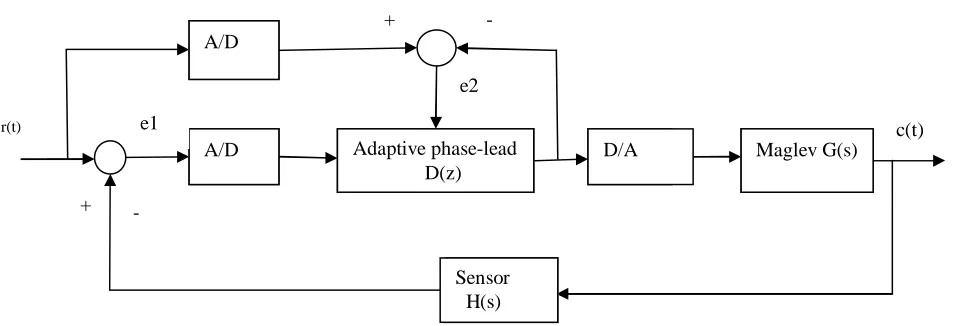
The block diagram of the adaptive control system is in Fig.1. In Fig. 1, r(t) is the input (or set point), c(t) is the output, D(z) is the digital phase-lead controller, G(s) is the plant transfer function, and H(s) is the sensor transfer function. The adaptive control scheme consists of two parts: the first part is using initial or updated phase-lead parameters, the controller will be taking in input samples, processing them, and sending them out to the maglev system through the D/A converter; the second part is updating the controller parameters. This process continues until the error signal e2 is approaching zero.
A digital non-adaptive phase-lead controller has the following form [3]:
D(z) 1
0 1 0 1
) 1 (
− − −
+
=
K bazz(1)
For programming convenience, let
where X(z) and Y(z) are the input and output of the controller in the z-domain, respectively, then
(
)
(
1
1)
(
)
0z
M
z
a
K
z
Y
=
+
− (2)and
X(z)=(1−b0z−1)M(z). (3)
Using the inverse z-transformation,
y
(
k
)
=
K
[
m
(
k
)
+
a
0m
(
k
−
1
)]
(4)And
m
(
k
)
=
x
(
k
)
+
b
0m
(
k
−
1
)
.
(5)As mentioned in section I, the C31 DSK has two multiplexed inputs. One is the primary input and the other is the auxiliary input. Denoting the primary input as IOPRI and the auxiliary as IOAUX, the detailed portion of the C31 DSK in Fig.1 is shown in Fig. 2, where e1 and y are input and output of the phase-lead controller, respectively.
E2 is then:
(6)
A quadratic objective function is created based on minimizing E2 with respect to the controller parameters:
(7)
Taking the first order partial derivative with respect to the controller parameters:
(8a)
(8b) r(t)
A/D
A/D Adaptive phase-lead D(z)
D/A Maglev G(s)
e1 Sensor H(s) e2 + - + - IOPRI (with r(t) as input)
IOAUX (with e1 as input) Adaptive Phase-lead + -
Fig. 1. The adaptive maglev control system
c(t)
y
[image:2.612.66.543.93.256.2]e2
Fig. 2. Detailed portion of the adaptive phase-lead controller
− = − = ( ) ( ) ( ) ) (
2 z Rz Y z Rz
E
(
)
1
)
1
(
1 1 0 1 0z
E
z
b
z
a
K
−
+
− −( )
2 2 1 00
,
)
2
(
a
b
E
J
=
2 1 0 1 0 2 11
1
)
1
(
)
(
−
+
−
=
−−E
z
b
z
a
K
z
R
( )
22 1 0 1 0 1 1
1
)
1
(
)
1
(
1
1 00
b
z
E
z
a
K
E
R
z b a J
−
+
+
−
=
− − − ∂∂ − 2 2 1 0 1 2 1 0 2 2 1 0 1 01
)
1
(
)
1
(
1
)
1
(
1
0
b
z
E
Using the first order approximation, the negative gradient is basically the product of reference signal R and error signal E1. Tests show that using E1 and E2 actually has a better convergence. Therefore, a modified gradient method was used as the search direction in updating the controller parameters. This also agrees with the general adaptive mechanism mentioned in [4]: new parameter = old parameter + (bounded step size) X (function of input) X (function of error). More specifically
III. IMPLEMENTATION OF THE ADAPTIVE PHASE-LEAD CONTROLLER USING THE C31DSK
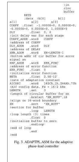
Following is the assembly language program ADAPTPl.ASM implementing the adaptive phase-lead controller.
)
9
(
)
(
)
(
)
(
)
1
(
0 2 10
k
a
k
e
k
e
k
n
a
a
+
=
+
β
−
)
9
(
)
(
)
(
)
(
)
1
(
0 2 10
k
b
k
e
k
e
k
n
b
b
+
=
+
β
−
MPYF3 *AR0++,*AR1--,R1 ;b[1]*dly[1]=b2u(n-2)
|| SUBF3 R0,R3,R3 ;input-b[0]*dly[0];R3=x(n)-b1u(n-1) MPYF3 *AR0++,*AR1++,R0 ;a[1]*dly[0];R0=a1u(n-1)
|| SUBF3 R1,R3,R2 ;u(n)=xn-b[0]*dly[0]-
;b[1]*dly[1]=x(n)-b1u(n-1)-b2u(n-2)
MPYF3 *AR0++,*AR1--,R1 ;a[2]*dly[1]=R1=a2u(n-2) ADDF3 R0,R1,R3 ;a[2]*dly[1]+a[1]*dly[0];R3=a1
;u(n-1)+a2u(n-2)
LDF *AR1,R4 ;dly[0];R4=u(n-1)
|| STF R2,*AR1++ ;dly[0] = dly; u(n-1)updated to
;->u(n)
MPYF3 R2,*AR0--,R2 ;dly*a[0];R2=a0u(n);point to a2 to
;adapt
|| STF R4,*AR1++ ;dly[1] = dly[0];u(n-2)->u(n-1) to
;update
ADDF3 R2,R3,R3 ;controller output;y=a0u(n)+a1
;u(n-1)+a2u(n -2) FIX R3,R7 ;convert to integer for output CALL IOPRI ;get reference desired signal d *ADAPTPL.ASM - Adaptive phase-lead
controller using the C31 DSK
.start ".text", 0x809900 ;starting address of text
.start ".data", 0x809C00 ;starting address of data
.include "AICCOM31.ASM" ;include AIC comm routines
.entry BEGIN ;start of code
.text ;assemble into text
BEGIN LDP @COEFF_ADDR ;init to data page 128
CALL AICSET ;initialize AIC
LDI @ERF_ADDR,AR6 ;error function address
LDI @XNB_ADDR,AR2 ;AR2=bottom addr of input xn to
;filter LDI LENGTH,BK
;BK=length of circular buffer PL CALL IOAUX ;get input error signal
FLOAT R6,R3 ;stage input
STF R3,*AR2++% ;store newest sample
This program is based on the combination of the IIR filter program and the adaptive filter for noise cancellation program in [2] and [5]. It consists of two major subroutines. Subroutine PL takes in input samples and calculates outputs of the phase-lead controller, using existing phase-lead parameters. It also calculates the error between desired output and actual output of the system. Subroutine ADAPT
updates the phase-lead parameters
a
0, b
0 using equation (9). Two inputs are required in this application, available on the AIC on board the DSK. While the primary input IOPRI is through an RCA jack, a secondary input IOAUX to the AIC is available on the DSK board from pin 3 of the 32-pin connector JP3. The secondary input is enabled from the setting in AICSEC in the program. The AIC communication;in circ buffer RETS
.data ;b[0] b[1] a[1] a[2] a[0]
COEFF .float -1.0000E+0, 0.0000E+0, -0.0000E+0, 0.0000E+0, 1.0000E+0 DLY .float 0, 0 ;init delay var for each stage COEFF_ADDR .word COEFF ;address of COEFF
DLY_ADDR .word DLY ;address of DELAY
XNB_ADDR .word XN+LENGTH-1 ;bottom addr of cir buffer for error signal xn
ERF_ADDR .word ERR_FUNC ;address of error function
ERR_FUNC .float 0 ;initialize error function
BETA .float 2.5E-12 ;rate of adaptation constant
AICSEC .word 162Ch,1h,244Ah,73h ;AIC config data, Fs = 16/2 kHz
LENGTH .set 3 ;Length of circular buffer for xn .brstart "XN_BUFF",16 ;align on 16-word boundary
XN .sect "XN_BUFF" ;section for buffer
.loop LENGTH ;loop length (3) times
.float 0 ;initialize buffer to zero
.endloop ;end of loop
.end ;end
[image:4.612.301.564.58.595.2]
Fig. 3. ADAPTPL.ASM for the adaptive
phase-lead controller
FLOAT R6,R4 ;R4=reference desired signal d SUBF3 R3,R4,R0 ;R0=error signal=d-y
MPYF @BETA,R0 ;ERR function=e*beta
STF R0,*AR6 ;store error function
CALL ADAPT ;call ADAPT subroutines
BR PL ;branch back/repeat with new input ;sample
;ADAPTATION ROUTINE
ADAPT MPYF3 *AR6,*AR2++%,R0 ;error function*x(n-(N-1))
;->R0=e rfx(n -2) LDF *AR0,R3 ;w(N-1) -> R3=a0
ADDF3 R3,R0,R2 ;w(n-1-i)+erf*x(n-(N-1
;-i));R 2=a0+ erfx( n-2) STF R2,*AR0-- ;store/upgrade a0 coeff
MPYF3 *AR6,*AR2++%,R0 ;erf*x(n-(N-1-i))->R0=erfx(n-1) LDF *AR0,R3 ;load subsequent w(k) ->R3=b0
ADDF3 R3,R0,R2
;w(n+1)=w(n)+erf*x(n);R2=b0+erf STF R2,*AR0++(2) ;store/upgrade b0 coeff
MPYF3 *AR6,*AR2++%,R0 ;R0=erfx(n);erf*newest sample
subroutine in AICCOM31.ASM, included in the ADAPTPL.ASM program, are set so that the extended precision registers R6 and R7 are used for input and output, respectively. The program was assembled using the assembler included in the C31 DSK package, and was run using Code Explorer. For initial conditions,
a
0 andb
0 are fixed at 1 and -1, respectively. The adaptation β in (9) is set to be 2.5E-12.IV. TEST RESULTS
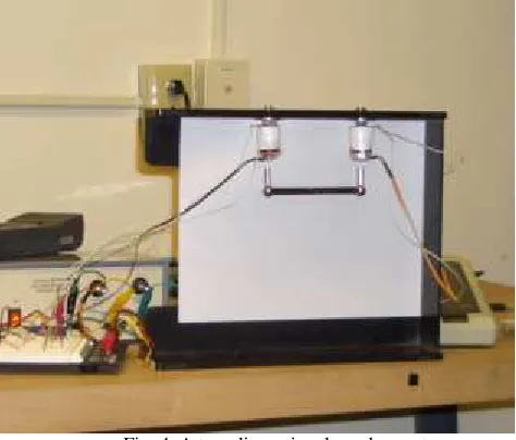
Tests were performed on the magnetic levitation control system (Figure 4). This system, in addition to the adaptive phase-lead controller, also includes the following key components:
Position Sensor
A Hall Effect sensor is used with an output that is proportional to the magnetic flux. This means that the closer to a magnet it gets, the greater the signal it produces.
PWM Control
The electromagnet is driven by a PWM (pulse with modulation) signal. This is a scheme mostly often used to control the speed of a DC motor. A repeating pulse changes its width to apply more or less power to the device over time. The pulse frequency is set by a capacitor.
Electromagnet Driver
The electromagnet driver should work to achieve a balance of push-and-pull. If the suspended object gets too close to the electromagnet, the electromagnet should push it away. Conversely if it falls too low the electromagnet should work at pulling it back up. The LM1820 driver chip has a built-in H-bridge that can reverse polarity of its output and is perfect for this application.
The system is both inherently nonlinear and open-loop unstable with the following linearized transfer function:
4 2
7
10 226 . 1
10 816 . 6 ) (
× −
× =
s s Gp
which is clearly unstable due to the location of one pole (110.735) on the right hand-side of the s-plane. The z-transform of Gp(s) gives (sampling period is 0.0001 sec.)
0000 . 1 000123 . 2
3408 . 0 3408 . 0 )
( 2
+ −
+ =
z z
z z
[image:5.612.325.562.69.271.2]G
Fig. 4. A two-dimensional maglev system
The adaptive phase-lead controller D(z), when converged, has the following parameters:
1 1
9891
.
0
0000
.
1
9901
.
0
0000
.
1
)
(
−−
−
−
=
z
z
z
D
V. CONCLUSION AND FUTURE WORK
A low cost two-dimensional magnetic levitation systems using a digital adaptive phase-lead controller is built and successfully tested. The maglev control system (non-linear, open-loop unstable) is a good example to complement the DC motor control system (linear, open-loop stable) currently taught in many control systems course in electrical and mechanical engineering majors. Combined with the new DSP technologies, this will make the control systems courses more exciting. On the other hand, adding another application in control to the DSP (or signals and systems) courses will make these seemingly theoretical courses more interesting. With a good understanding of the C31 DSK, Students can then use the newest DSP technologies to explore other applications. Therefore, this project is not just about adding an isolated example into the existing courses, it introduces new ways how control and DSP courses can be taught, and will significantly impact the teaching of these two major electrical engineering and mechanical areas (control and DSP). The new materials can also be easily adapted by other institutions due to the low costs involved. The cost of the parts for each magnetic levitation system is less than $150.
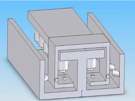
Fig. 5. Possible Design of a three-dimensional maglev system
REFERENCES
1. K. Astrom, B, Wittenmark, Adaptive Control, 2nd Ed, Addison Wesley, 1995.
2. R. Chassaing, Digital Signal Processing Laboratory
Experiments Using C and the TMS320C31 DSK, Wiley,
1999.
3. C. Phillips, H. Nagle, Digital Control Systems Analysis
and Design, Prentice Hall, 1995.
4. Y. Dote, Servo Motor and Motion Control Using Digital
Signal Processors, Prentice Hall, 1990.
5. J. Tang, R. Chassaing, “PID Controller Using the TMS320C31 DSK for Real-Time DC Motor Control,”
Proc. of the 1999 Texas Instruments DSPS Fest,