UNIVERSITY TUN HUSSEIN ONN MALAYSIA
STATUS CONFIRMATION FOR MASTER’S PROJECT REPORT DEVELOPMENT OF TIME DELAY CURRENT CONTROLLER USING
RASPBERRY PI FOR 3 PHASE ACTIVE POWER FILTER FOR NONLINEAR LOAD IMPROVEMENT
ACADEMIC SESSION: 2015/2016
I, SALLEHUDDIN BIN BACHOK @ TUNDERANG, agree to allow this Master’s Project Report to be kept at the Library under the following terms:
1 This Master’s Project Report is the property of the Universiti Tun Hussein Onn Malaysia. 2 The library has the right to make copies for educational purposes only.
3 The library is allowed to make copies of this report for educational exchange between higher educational institutions.
4 ** Please Mark (√)
CONFIDENTIAL (Contains information of high security or of great importance to Malaysia as STIPULATED under the OFFICIAL SECRET ACT 1972)
RESTRICTED (Contains restricted information as determined by the Organization/institution where research was conducted)
FREE ACCESS
Approved by,
(WRITER’S SIGNATURE) (SUPERVISOR’S SIGNATURE)
Permanent Address:
NO.112 JALAN CEMPAKA SATU TAMAN CEMPAKA SEROM 6 84410 LEDANG, JOHOR
Date : ___________________________ Date: _____________________________
NOTE:
DEVELOPMENT OF TIME DELAY CURRENT CONTROLLER USING RASPBERRY PI FOR 3 PHASE ACTIVE POWER FILTER FOR
NONLINEAR LOAD IMPROVEMENT
SALLEHUDDIN BIN BACHOK @ TUNDERANG
A project report submitted in partial fulfilment of the requirement for the award of the
Degree of Master Electrical Engineering
Faculty of Electrical and Electronics Engineering University Tun Hussien Onn Malaysia
II
I hereby declare that the work in this project report is my own except for quotations and summaries which have been duly acknowledged
Student : ………..………
SALLEHUDDIN BIN BACHOK @ TUNDERANG
Date : ………..
Supervisor : ………
III
IV
ACKNOWLEDGEMENTS
Alhamdulillah has been reciting to our Allah with the blessing that has been given to me done these thesis reports smoothly.
I would like thanks to the persons or individual those help me a lot in researching and completing this project, lots of individuals that sincere helping in handling this project either teaching me to handling this projects, give an idea and motivational effort, research had been proceeding according to plan and successfully along with patients and completing the thesis.
A lot of thanks to my supervisor Dr Shamsul Aizam bin Zulkifli because guiding me to handle and finally complete all the tasks, good commitment and a lot of ideas during discussion, it can help us to make a better improvement for our project. His patience and determination towards our habits is greatly appreciated.
V
ABSTRACT
VI
ABSTRAK
VII
TABLE OF CONTENTS
TITLE I
DECLARATION II
DEDICATION III
ACKNOWLEDGEMENTS IV
ABSTRACT V
ABSTRAK VI
TABLE OF CONTENTS VII
LIST OF TABLES IX
LIST OF FIGURES Error! Bookmark not defined. LIST OF SYMBOLS AND ABBREVIATIONS XII
CHAPTER 1 INTRODUCTION 1
1.0 Introduction Error! Bookmark not defined.
1.1 Project Background 1
1.2 Problem Statement 2
1.3 Aim and objectives 4
1.4 Limitations / scope of the research 4
1.5 Outline of the thesis 5
CHAPTER 2 LITERATURE REVIEW 6
2.1 Harmonics as a power quality problem 6
2.2 Linear Loads 8
2.3 Unbalanced Load or Non-Linear Loads 8
2.3 Three phase active power filter (APF) 9
2.4 Control Strategy of active power filter (APF) 11
2.5 Raspberry Pi 15
2.4.1 PID Controller 12
2.4.2 Fuzzy logic controller 124
VIII
CHAPTER 3 METHODOLOGY 19
3.1 Block Diagram 19
3.2 Gate Driver Design 211
3.3 Time Delay Current Controller Design 244
3.4 Current sensor 255
3.5 Inverter Circuit Design 277
3.6 Analogue to Digital Converter 29
CHAPTER 4 RESULTS AND ANALYSIS 32 4.1 Introduction 32 4.2 Simulation Result 32 4.3 Hardware Result 399 4.3.1 Linear load analysis 39
4.3.2 Nonlinear load analysis 43
4.3.3 Gate driver analysis 46
4.3.4 Active power filter analysis 48
4.3.5 Close loop analysis 51
CHAPTER 5 CONCLUSION AND RECOMMENDATIONS 554
5.1 Conclusion 554
5.2 Recommendations 55
REFERENCES 58
2.5.1 Specification of Raspberry Pi 166
2.5.2 GPIO of Raspberry Pi 188
4.2.1 Nonlinear load 3233
4.2.2 Time Delay Current Controller 3434
4.2.3 Active Power Filter (Inverter) 36
IX
LIST OF TABLES
2.1 Specification of the Raspberry PI 17
3.1 List of the components for gate driver circuit 21
3.2 List of component for three phase APF 29
X
LIST OF FIGURES
Figure 1.1 Block Diagram of the Project 2
Figure 2.1 The Sources of Harmonics In Power Distribution 7
Figure 2.2 Circuit diagram of Nonlinear load design 9
Figure 2.3 The configuration of a three phase active power filter 9
Figure 2.4 Model of APF 10
Figure 2.5 The configuration of the active power filter by their group 11
Figure 2.6 Block Diagram of PI controller 12
Figure 2.7 A block diagram of a PID controller in a feedback loop 13
Figure 2.8 Time delay current control for the active power filter 15
Figure 2.9 A raspberry Pi Controller 16
Figure 2.10 Hardware Configuration of Raspberry Pi 16
Figure 2.11 The layout of the GPIO pin header for the Raspberry 18
Figure 3.1 Block diagram of the project 19
Figure 3.2 The schematic diagram of the gate driver circuit 22
Figure 3.3 Hardware of gate driver circuit 23
Figure 3.4 Design of the time delay current controller 24
Figure 3.5 Circuit for current sensor 26
Figure 3.6 Current sensor (SN_ACS712) hardware configuration 26
Figure 3.7 Circuit diagram of inverter (Active Power Filter) 27
Figure 3.7 Design of three phase APF 28
Figure 3.9 Hardware circuit of the three phase APF 28
Figure 3.10 Design communication between current sensors with 30
Raspberry Pi using MCP3008
Figure 4.1 Simulation design of the non linear load 33
Figure 4.2 Result from the simulation design of the non linear load 33
Figure 4.3 The time delay current controller design in Matlab 35
Figure 4.4 Current Compensation signal current compensation and the 35
XI
Figure 4.5 The result compensated current that are transformed into PWM 35
Figure 4.6 Design of the simulation active power filter circuit 36
Figure 4.7 Result of the simulation of current and voltage before filter 37
Figure 4.8 Result of the simulation of current and voltage after filter 38
Figure 4.9 Simulation of pulse generation for the Raspberry Pi 38
Figure 4.10 The output from the simulation in the Matlab 39
Figure 4.11 Diagram input sensor for linear load 40
Figure 4.12 Input Sensor with ADC 40
Figure 4.13 Result ADC input sensor for linear load 41
Figure 4.14 Voltage and current for linear load 41
Figure 4.15 Three phase current for linear load 43
Figure 4.16 Diagram input sensor for nonlinear load 44
Figure 4.17 Result ADC input sensor for nonlinear load 44
Figure 4.18 Nonlinear load result 45
Figure 4.19 3 phase nonlinear load result 45
Figure 4.20 Diagram for gate driver output 46
Figure 4.21 Gate driver circuit 47
Figure 4.22 Result for gate driver output pulses 47
Figure 4.23 Diagram for inverter output 48
Figure 4.24 Inverter output circuit 48
Figure 4.25 Result for inverter output (Voltage L-L: A-B) 49
Figure 4.26 Result for inverter output (Voltage L-L: A-C) 49
Figure 4.27 Result for inverter output (Voltage L-L: B-C) 50
Figure 4.28 Closed loop diagram with time delay current controller for 51
3phase APF with nonlinear load
Figure 4.29 Result for 3 phase current output inverter with non-linear load 52
XII
LIST OF SYMBOLS AND ABBREVIATIONS
APF - Active Power Filter
PID - Proportional Integral Derivative
PI - Proportional Integral
I - Integral
VFD - Variable Frequency Drives
SMPS - Switch-mode Power Supply
SPWM - Sinusoidal Pulse Width Modulation
UPS - Un-interruptible Power Supply
MOSFET - Metal Oxide Semiconductor Field Effect Transistor
IGBT - Insulated-Gate Bipolar Transistor
VSI - Voltage Source Inverter
CSI - Current Source Inverter
VSAFs - Voltage Source Active Filter
CSAFs - Current Source Active Filter
DC - Direct Current
AC - Alternative Current
VDC - Voltage DC
VAC - Voltage AC
THD - Total Harmonic Distortion
PWM - Pulse Width Modulation
1
CHAPTER 1
INTRODUCTION
This chapter will introduce about project background, problem statement, aim, objectives and scopes of the development of time delay current controller using Raspberry PI for 3 phase active power filter for unbalanced load improvement.
1.1 Project Background
In industries, mostly Active Power Filter (APF) has been widely applied in power system distribution for compensating the current harmonics and improving the power quality that are caused by unbalanced load and non-linear load. The performance and quality of active power filter is influenced by the current control techniques.
There are many types of current control have been studied over years and still prefer as its good dynamic scan make out the output to a steady state as the smallest number of time steps.
2
while interharmonics can be defined a frequency component of a periodic quantity that is not an integer multiple of the frequency at which the supply system is operating [1]. For this project the purpose is to design a time delay current controller by using Matlab and use the Raspberry Pi as hardware to reduce the effect of the harmonics that are cause by unbalanced load. As known that Raspberry Pi is a new technology which like a credit card sized computer which are power by ARM1176JZF-S 700 MHz processor. It is an open source system which can integrates with various kind of software that can be used to handle many applications such as controller, camera, games and etc.
In this project the ability of the Raspberry Pi are being tested by acting as time delay current controller. Which in this project a three phase AC voltage source are being supplied to an unbalanced load to create the harmonics affect. In this condition an active power filter (APF) will be introduce and connected into the circuit and will compensate the distortion current until it will become a sinusoidal waveforms.
[image:15.595.129.482.443.528.2]Here, the Raspberry Pi will develop a time delay current controller for the active power filter whereas it will trigger the active power filter (APF) to react when there is a distortion between the supply current and the load current.
Figure 1.1: Block Diagram of the Project
1.2 Problem Statement
Power quality can be defined as an interaction between supplies power system and load power. The IEEE standards [2] defines that the power quality as “The concept of powering and grounding electronic equipment in a manner that is suitable to the operation of that equipment and compatible with premise wiring system and other connected equipment.”
3
It has many disadvantages to the system that it will affect the power quality, heat rising and also it can damage the whole system. There are standards that determine the maximum allowable level for each harmonic in the Alternative Current (AC) system [3] .When excessive harmonic voltage and current are generated, filters are usually installed to reduce the harmonic distortion. There are two functions to connect harmonic filter at line distribution systems as listed below.
(i) to reduce the harmonic voltage and current in the AC system below the
permitted levels
(ii) to provide some of the reactive power absorbed by the converter system[3]
The nonlinear load becomes a problem because the nonlinear load will affect the current in the system. With nonlinear load, the resistance will varies and not constant, will trigger a non- sinusoidal waveform in the system [4]. The THD of nonlinear load can reach over 100% without any other compensation [5]. This high presence of THD will have effect such as degrade the power quality in the system, increase heat in load, and some other load will not function properly.
APF is used as to minimize the harmonics, but it also has several problems such as the presence of resonance and lead to the oscillation in the compensated current [11]. When the design is not precise, the noises from the APF become apparent and thus the output current is not the same with the desired one.
4
1.3 Aim and Objectives
The aim of this research is to design the time delay current controller for 3 phase active power filter (APF) for nonlinear load improvement. There are 3 main objectives to achieve this result as given below:
(i) to Development and implementation of a time delay current controller
by using MATLAB and Raspberry Pi for output-following signal in order to reduce the harmonic effect
(ii) to Interface between the MATLAB Simulink and Raspberry Pi.
(iii) to design and built a low cost current controller for three phase non linear load by using Raspberry Pi.
1.4 Limitations / Scope of the Research
The limitation and scope of this project is to research the characteristic and effect of the harmonic of 3 phase nonlinear load and to evaluate the performance of Active Power Filter (APF) based on time delay current controller. In this project the scope of this project are:
1. Research of the behavior of the time delay current control technique by using
Matlab/Simulink software for the simulation and hardware development.
2. Construct the 600W APF circuit, where the maximum Voltage 60Vdc and the
maximum current 10A, in order to reduce the harmonic distortion.
3. Interface the Active Power Filter (APF) by using Matlab/simulink using
Raspberry Pi board as main controller.
4. Applied 3 phase rectifier as prototype of Nonlinear load with 10 Ω 50W (Wire
Wound resistor).
5
1.5 Outline of the Thesis
This report divided into 5 chapters which are introduction, literature reviews, methodology, result and analysis, conclusion and recommendation.
This chapter is only about the introduction of this proposed project, it will cover the idea about aim, objective and limitation of this project.
Chapter 2 covers the background and literature reviews. In this Chapter also describes the harmonics as a power quality problem. It will cover all the fundamental principles and the previous work that has been researched on.
Chapter 3 will cover the methodology of this project. The methodology is detailed of the works that must be done in order to achieve the objectives of this research.
Chapter 4 explains on the experiment results and discusses while doing the preliminary test by using Matlab. Simulation and practical results are also demonstrated in this chapter.
6
CHAPTER 2
LITERATURE REVIEW
This chapter will introduce the previous research or works have been done before about harmonics power quality, 3 phase active power filter (APF), unbalanced load as well as the controller used to compensate the current shortage in the unbalanced system. The research including the usage of Matlab and Raspberry Pi for testing and the results acquired. Other than that, this chapter will emphasize the importance of this project, and the differences between it with other works.
2.1 Harmonics as a Power Quality Problem
7
reduce the harmonic effect and increase up the overall efficiency of the distribution system.
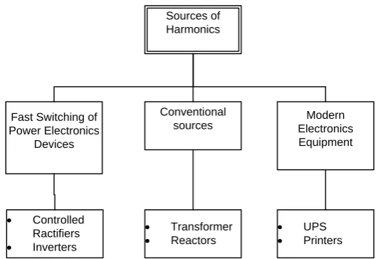
There are many sources that can produce harmonics in power distribution system. Figure 2.1 illustrate the different sources of harmonics in power distribution system.
Conventional
sources Electronics Modern Equipment Fast Switching of
Power Electronics Devices
Sources of Harmonics
· Controlled Ractifiers
· Inverters
· Transformer
· Reactors
· UPS
[image:20.595.185.451.193.375.2]· Printers
Figure 2.1: The Sources of Harmonics In Power Distribution
They can be categorized of their mains areas which are fast switching associated of power electronic devices, conventional sources such as electrical rotating machines and transformers and modern electronics equipment [7].
Harmonics have a number of undesirable effects on the distribution system. They can be categorized as short and long term. Short term effect are usually most noticeable and are related to excessive voltage distortion but for the long term effects are often go undetected and are usually related to increased resistive losses or voltage losses [6].
8
2.2 Linear Loads
AC electrical loads where the wave shape of the steady state current will follow the wave shape of the applied voltage. When a pure sinusoidal voltage is passed through the resistive element, then the shape of the current wave form will be purely sinusoidal without distortion [9].
Examples of the linear loads are power factor improvement capacitors, indecent lamps, heaters and etc. The characteristics of linear load can be state as below:
1. In AC circuits, linear loads’ voltage and current waveforms are sinusoidal, so
The current at any time is proportional to voltage and these loads does not change the shape of the waveform of the current, but may change the relative timing (phase) between voltage and current.
2. Linear loads’ impedance remains fixed with changing the applied voltage. The
fixed impedance means that the current drawn by the linear load will be sinusoidal as like the voltage and the current at any time will be proportional to voltage.
3. Linear loads don’t produce any new frequency (harmonics) or change the
applied frequency. If the supply current to the linear loads is in sinusoidal shape, the linear loads will make the supply current remains sine wave without any changes.
2.3 Unbalanced Load or Non-Linear Loads
9
D1 D2 D3
D4 D5 D6
[image:22.595.195.444.65.277.2]Phase A Phase B Phase C
Figure 2.2: Circuit diagram of Nonlinear load
2.3 Three Phase Active Power Filter (APF)
In this last decade, 3 phase APF has been widely used due to the intensive use of electric and electronics applications. It is recently developed to suppressing the current harmonics and compensating the reactive power [10]. Figure 2.3 shows the configuration of a three phase active power filter.
NON LINEAR LOAD
ACTIVE POWER FILTER POWER
SYSTEM
SUPPLY CURRENT
LOAD CURRENT
if
C
FILTER OUTPUT CURRENT
VDC
[image:22.595.183.466.536.729.2]10
This cause that many high end applications have been using 3 phase rectifiers such as arc welding, 3 phase ac induction motors and so on that will contribute to the non-sinusoidal current. This non-sinusoidal current will generate harmonics in the system and the power quality of the system will reduce. So, in order to reduce this harmonics, the 3 phase APF is used. The configuration of simple 3 phase APF has been shown in Figure 2.4. The basic principle of APF is to utilise power electronics technologies to produce specific currents components that cancel the harmonic currents components caused by the nonlinear load [6]. The harmonics will cancel out with the harmonics generated by the nonlinear system and as the result; the pure sinusoidal current will formed.
A
B
C
[image:23.595.153.478.347.513.2]Ca
Figure 2.4: Model of APF [12]
11
APF can be connected in several power circuit configurations as illustrated in the block diagram shown in Figure 2.5 [6]. In general, they are divided into three main categories, namely shunt APF, series APF and hybrid APF [6].
Active Power Filter
Shunt APF Series APF Hybrid APF
Current Source Voltage source
Shunt APF + series APF Series APF + Series APF Shunt APF + Shunt PF
[image:24.595.117.515.151.397.2]APF in Series with shunt PF
Figure 2.5: The configuration of the active power filter by their group [6]
2.4 Control Strategy of Active Power Filter (APF)
Most part of technical literature about active filters deals with solely its application in balanced three-phase systems. The filter is connected to the electric installation through coupling inductors, for which they circulate currents synthesized for the current controllers, characterizing the active filter as controlled current source. The strategy to produce the correct control is composed two piece basic: a system of identification of the references and a system of current control [13].
𝑢(𝑡) = 𝐾𝑝𝑒(𝑡) + 𝐾𝑖∫ 𝑒(𝜏)
𝑡
0
𝑑𝜏 + 𝐾𝑑𝑑𝑒(𝑡) 𝑑𝑡
12
[image:25.595.171.471.152.216.2]distribution. When the active filter is used in systems unbalanced, the compensator has still the function to determine the compensation currents that become possible the balancing of the phases and the elimination of the neutral current.
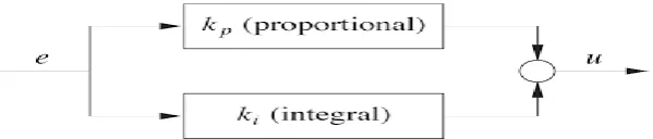
Figure 2.6: Block diagram of PI controller
With the potential application of the modern control techniques, the traditional way by using PI controller is still a prefer choice for voltage vector modulation based current controllers as in Figure 2.6 and the equation of PI controllers are express in equation 2.1. For the PI controller, the filter currents are detected and transformed from three-phase reference frame to the a–b frame and then subtracted from the reference currents to detect the current errors. The PI controllers here are actually converters, which convert current errors into reference voltages. The reference voltages are fed to the vector modulation unit to generate PWM switching signals, where us is the utility supply voltage vector, if is the filter output current vector.
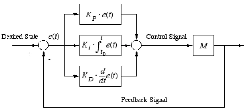
2.4.1 PID Controller
PID controller can be attributed partly to their robust performance in a wide range of operating conditions and partly for their practicality engineers can operate them in a simple and straightforward manner. Proportional-Integral-Derivative (PID) controller is prominent for its simplicity [13]. A PI controller is a common mechanism used in industrial control applications. A PID controller is capable used for regulation of temperature, pressure, flow, speed and other process variables. PID controlled system is a combination of three elements which are proportional, integral and derivative.
𝑢(𝑡) = 𝐾𝑝𝑒(𝑡) + 𝐾𝑖∫ 𝑒(𝜏)
𝑡
0
𝑑𝜏 + 𝐾𝑑𝑑𝑒(𝑡) 𝑑𝑡
13
[image:26.595.119.517.312.492.2]multiplied by a negative (for reverse action) proportional constant P, and added to the current output. P represents the band over which a controller’s output is proportional to the error of the system. For integral, the error is integrated (averaged) over a period of time, and then multiplied by a constant I, and added to the current control output. I represent the steady state error of the system and will remove measured value errors. Derivative is the rate of change of the error is calculated with respect to time, multiplied by another constant D, and added to the output. The derivative term is used to determine a controller’s response to a change or disturbance of the process temperature. The larger the derivative term, the more rapidly the controller will respond to changes in the process value.
Figure 2.7 A block diagram of a PID controller in a feedback loop
14
2.4.2 Fuzzy Logic Controller
Fuzzy logic controller (FLC) has been significance a good alternative solution in many applications [15]. The advantages of fuzzy logic controllers are more robust than conventional controllers; there is no specific requirement a mathematical model and able to handle non-linearity. FLC is the evaluation of a set of simple linguistic rules to determine the control action [14] [15]. Fuzzy Logic incorporates a simple rule-based,
for example IF X AND Y THEN Z approaches to a solving control problem rather than
attempting to model a system mathematically. The FLC model is empirically-based, relying on an operator’s experience rather than their technical understanding of the system.
The desired inverter switching signals of the shunt active filter are determined according the error between the compensate currents and reference currents. According [14] produced a paper on Fuzzy Logic controller for shunt Active Power Filter; the paper presents Active Power Filter based in detection load current and harmonic voltage at the point of installation by using the fuzzy logic method and to improve compensation capability of APF. The shunt APF is implemented with PWM current controlled voltage source inverter and switching patterns are generated through a fuzzy logic control.
15
2.4.3 Time Delay Current Controller
In a conventional digital control system the time delay is usually dtermine as at least one sampling step because of data sampling, computation and PWM control signal sending out to process, so it is only at the next sampling instant that the consequence of this control action will be observed. Figure 2.8 shows the equivalent control block
diagram of the current control loop, where L represents the line inductance and e2sTd
represents the effect of computational time delay [11].
The delay could cause significant overshoot and oscillation in the case of high di/dt current regulation. To remove the effect of dead in the time delay Td from the closed-loop system, a Smith predictor is deployed in the current control loop [11]. Here the line inductor model included is treated as delay-free model and has been used to generate the output signal. This delay free output signal is then used in the conventional feedback loop, instead of system output. To ease for the errors in the delay free model, the separate delay parameter, e2sTd , has been introduced and implemented. To simplify the implementation of the Smith predictor in a digital control system, in this work, the Smith predictor is only deployed in the proportional (deadbeat) current control loop [14].
PID Controller
Delay 1/S
+
-
if [image:28.595.192.471.498.613.2]ief
Figure 2.8 Time delay current control for the active power filter[11]
2.5 Raspberry Pi
16
[image:29.595.156.520.111.340.2]integrates with various kind of software that can be used to handle many applications such as controller, camera, games and etc.
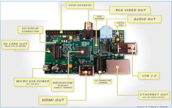
Figure 2.9: A Raspberry Pi Microcontroller
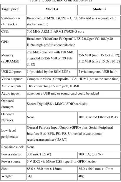
2.5.1 Specification of Raspberry Pi
[image:29.595.205.433.561.728.2]It come with version whereas Model A and Model B, which are Model A is cheaper than the Model B. It has some differences between this model where the Model A has a 256MB memory, which come with single USB port and doesn’t have any Ethernet port whereas Model B has 512MB memory, 2 USB port and an Ethernet port as in Table 2.1. Figure 2.10 shows the hardware configuration of Raspberry Pi.
17
Table 2.1: Specification of the Raspberry PI
Target price: Model A Model B
System-on-a-chip (SoC):
Broadcom BCM2835 (CPU + GPU. SDRAM is a separate chip stacked on top)
CPU: 700 MHz ARM11 ARM1176JZF-S core
GPU: Broadcom VideoCore IV,OpenGL ES 2.0,OpenVG 1080p30
H.264 high-profile encode/decode
Memory (SDRAM)iB
256 MiB (planned with 128 MiB, upgraded to 256 MiB on 29 Feb 2012)
256 MiB (until 15 Oct 2012); 512 MiB (since 15 Oct 2012)
USB 2.0 ports: 1 (provided by the BCM2835) 2 (via integrated USB hub)
Video outputs: Composite video | Composite RCA, HDMI (not at the same time) Audio outputs: TRS connector | 3.5 mm jack, HDMI
Audio inputs: none, but a USB mic or sound-card could be added
Onboard
Storage: Secure Digital|SD / MMC / SDIO card slot
Onboard
Network None 10/100 wired Ethernet RJ45
Low-level peripherals:
General Purpose Input/Output (GPIO) pins, Serial Peripheral Interface Bus (SPI), I²C, I²S, Universal asynchronous
receiver/transmitter (UART) Real-time clock None
Power ratings: 300 mA, (1.5 W) 700 mA, (3.5 W)
Power source: 5 V (DC) via Micro USB type B or GPIO header
Size: 85.0 x 56.0 mm x 15mm 85.0 x 56.0 mm x 17mm
18
2.4.2 General Purpose Input or Output (GPIO) of Raspberry Pi
[image:31.595.195.446.262.568.2]On the raspberry Pi, it has several type of interfaces and it can be configure used for a lot of applications. It has 17 pins available to operate in GPIO mode and it also can be configurable whether as input or output pins. Each of them carries only one bit data. The GPIO voltage levels are 3.3 V and are not 5 V tolerant. There is no over-voltage protection on the board. Its intention is for the purpose of person who is interested in serious interfacing which will use an external board with buffers, level conversion and analog I/O. Figure 2.11 the layout of the GPIO pin header for the Raspberry Pi.
19
CHAPTER 3
METHODOLOGY
This chapter will discuss more about methodology of this project has been outlined to achieved the desired output. This methodology divide into five basic parts which are research, unbalanced load problem, time delay Current Controller Design, Gate Driver circuit design, current sensor design, Active Power Filter Design and lastly interfacing between raspberry PI and hardware.
3.1 Block Diagram
NON LINEAR LOAD
3 PHASE INVERTER
GATE DRIVER CIRCUIT
TIME DELAY CONTROLLER CURRENT
[image:32.595.112.518.418.647.2]SENSOR
Figure 3.1: Block diagram of the project
20
consists of five main parts which are the DC power supply as the input, three phase inverter, current sensor as a feedback input current to the controller, gate driver circuit as an isolator circuit and PWM signal generator, and time delay current controller. The first part is when a DC input voltage fed into a three phase inverter system, this will transform the inverter and performs it as Active Power Filter (APF). The gate drivers use a 5 Vdc while the inverter input voltage depends on the loads that need to be powered.
Second part is the gate driver circuit which has a function that to double up the PWM signal from the Raspberry Pi and also perform as isolator circuit. The gate driver will double up the number of the amplitude of the signal PWM to the three phase inverter. For this project, the gate driver will produce six PWM signal from controller and it means every gate of power MOSFET or IGBT will control by Raspberry Pi.
Third part is 3 phase inverter, the general function of the inverter is to convert the DC voltage to the AC voltage. The focus of three phase inverter in the system is to produce a quality of three phase current APF to the system. The 3 phase inverter also known as the six switch inverter type or full bridge inverter and it will receive the output PWM from the gate driver. The fourth part is current sensor, Current sensor are connected to each voltage phases for measure the line current that flow from supply to nonlinear load and the output of sensor will used as a feedback controller.
21
3.2 Gate Driver Design
[image:34.595.225.457.291.481.2]The gate driver circuit are design to amplify the PWM input from the current controller, it is because of the pulse and amplitude doesn’t meet the criteria for the power transistor for switching purpose and isolate controller circuit with power circuit. The circuit are consist of several component that are listed in Table 3.1.
Table 3.1: List of the components for gate driver circuit
No Component Unit
1 IC 7414 3
2 IC 4081 3
3 HCPL3120 6
4 Capacitor 1nF 6
5 Resistor 4.3kΩ 2
6 Resistor 560Ω 2
7 Resistor 10Ω 2
8 Resistor 10kΩ 12
22
Figure 3.2: The schematic diagram of the gate driver circuit
23
Figure 3.3: Hardware of gate driver circuit
24
[image:37.595.119.519.133.314.2]3.3 Time Delay Current Controller Design
Figure 3.4: Design of the time delay current controller.
Although the current controller provides a very fast dynamic response, it is very sensitive to the time delay in digital control systems. In a conventional digital control system the time delay is usually at least one sampling step because of data sampling, computation and PWM control signal sending out to process, so it is only at the next sampling instant that the consequence of this control action will be observed.
The idea is to create a system that can be controlled as if it was its own minimum phase equivalent. Some knowledge about the controlled system is required to be able to predict its reaction. With this information, it is possible to make the predictable current signal available to the feedback loop before the delay time. This is done by adding the predicted current to the feedback signal without a delay. The feedback loop then “sees” the predicted value of the current at the same time, when it is actually generated. In digital motion control systems this is easily implemented. The predicted signal has to be subtracted from the feedback signal again after the delay time has elapsed, because at that time the regular feedback signal contains the information of the real effect of the voltage command.
X(s) Y(s)

![Figure 2.3: The configuration of a three phase active power filter [11]](https://thumb-us.123doks.com/thumbv2/123dok_us/8759485.893639/22.595.195.444.65.277/figure-configuration-phase-active-power-filter.webp)
![Figure 2.4: Model of APF [12]](https://thumb-us.123doks.com/thumbv2/123dok_us/8759485.893639/23.595.153.478.347.513/figure-model-of-apf.webp)
![Figure 2.5: The configuration of the active power filter by their group [6]](https://thumb-us.123doks.com/thumbv2/123dok_us/8759485.893639/24.595.117.515.151.397/figure-configuration-active-power-filter-group.webp)
![Figure 2.8 Time delay current control for the active power filter[11]](https://thumb-us.123doks.com/thumbv2/123dok_us/8759485.893639/28.595.192.471.498.613/figure-time-delay-current-control-active-power-filter.webp)