Abstract Chimera technique has broad applications in complex flow field simulations because of its convenience of the arbitrary boundary interfaces and the easiness of gird generations of subzones. However, the main disadvantage or challenging difficulty lies in the global conservative information exchange between different zones or components. This work aims at assessing the conservation and effects of the mass flux based interpolation (MFBI) in a chimera multi-grid flow solver where Reynolds-Averaged Navier-Stokes (RANS) equations and Boldwin-Lomax turbulence model are introduced to calculate the viscous flows over a multi-element airfoil (NAWC1F2.2) with a flap. Numerical results reveal that, compared to the direct interpolation scheme, the performance of global conservation of MFBI are much better and more coincident with wind-tunnel experiments.
Index Terms Chimera Technique; Conservative Algorithm;
Multi-element Airfoils; Aerodynamics.
I. INTRODUCTION
For the reason that the chimera grid technique allows the arbitrary boundary interfaces, in which the grids can be generated independently for different zones or components and grid overlaps are allowed, the chimera grid approach is preferred over the single-block approach and the patched multi-block approach in the context of using structured grid to handle topologically complex geometries. Typical applications are reported in various engineering fields ranging from aerospace engineering [1], biomechanics engineering [2] to hydraulics engineering [3]. However, there are also disadvantages of chimera grid technique, two of which are addressed following. The first is the hurdle of creating the data structure that specifies the interconnectivity among the overset grids. The other which is more challenging is the difficulty of enforcement of global conservation. The generation of the grid connectivity for a system of overlapping grids is an expensive and daunting task, although some recent tools can be enforced, such as hole cutting method or implicit hole cutting method[4,5] and in some particular junction regions of two bodies, collar grid or visual grid method[6,7] can be implemented to overcome the deficiencies. Furthermore, references [8, 9] reveal that some versions of connectivity codes have been developed by
Manuscript received March 3, 2009. 8
Xu Kangle, PhD, Mechanics and Engineering Science Dep., Fudan Univ., Shanghai 200433, China,, email: [email protected] )
Sun Gang, Prof., corresponding author, Mechanics and Engineering Science Dep., Fudan Univ., Shanghai 200433, China, Tel: 0086-21-65642740,Fax: 0086-21-65642742; email:[email protected];
NASA with the attempt to ameliorate the difficulty of the grids connectivity.
Another critical and more challenging issue in solving flow problems by chimera grids is to exchange solution information at grid interfaces. Some efforts and researches have been made and Benek [10], Ray [11] and Berger [12] are some of early typical researchers on this issue. Reference [13] takes a short but good review of pioneering literatures. Currently, in order to facilitate information exchange, the direct interpolation or Lagrange interpolation [14] of both velocity and pressure at grid interfaces from adjacent grids is often the first choice. In case of overset grids, such direct interpolation is frequently realized by bi-linear or tri-linear interpolation. The advantage of the direct interpolation is that it is straightforward and easy to implement. In addition to this, H.S. Tang [15] has shown that the direct interpolation is a second-order accurate scheme. However, the need for accurate conservative grid interfaces has been illustrated by amount of literatures [11, 12, 16, and 20]. Berger [12] gives a discussion of conservative interpolation in overlapping grids. Hubbard and Chen [20] developed a finite-analytic, SIMPLE-type algorithm for solving the Navier–Stokes equations on Chimera overset grids. They reported that using tri-linear interpolation at grid interfaces for all flow variables leads to oscillatory pressure and velocity fields. Part-Enander and Sjogreen [16] also compared the effects of both conservative and non-conservative interpolation on slow moving shock problems, and got a conclusion that the non-conservative interpolation can lead to a large error. From above literatures, it can be obviously seen that it is often advantageous to use a numerical scheme in conservation form for flow problems involving discontinuities or sharp gradients.
The contributor to these deficiencies is that the physical sense of a numerical scheme is not under consideration at the time when the direct interpolation is implemented. Not ideally, the physical (mass, momentum and energy) conservation laws are not satisfied in the entire domain. However, the point which needs to be addressed is that simultaneous achievement of both conservation of all physical quantities (mass, momentum and energy) and accuracy can be a really difficult task. In fact, for some problems, compromise has been made between enforcing the flux conservation and maintaining the comparable interpolation accuracy in both the grid interface and the interior regions. Researchers Tang HS [18, 19] and Jones SC [18] modified the standard interpolation and a mass flux based interpolation (MFBI) interface algorithm was proposed for Chimera grids. MFBI determines velocity and pressure at grid interfaces by mass conservation and interpolation, and it
Assessment of an Interface Conservative
Algorithm MFBI in a Chimera Grid Flow
Solver for Multi-Element Airfoils
is easy to implement while maintaining good efficiency and desirable accuracy.
In this paper, the chimera grids approach, Reynolds-Averaged Navier-Stokes (RANS) equations and Boldwin-Lomax turbulence model are adopted to calculate the viscous flows over a multi-element airfoil (NAWC1F2.2) with a flap. The main attention is paid to the assessment of the conservation and effects of the mass flux based interpolation (MFBI) algorithm in chimera grid flow solver for multi-element airfoils.
II. MASS FLUX BASED INTERPOLATION SCHEME
In the MFBI algorithm, the velocity component in the normal direction of grid interfaces is determined by enforcing mass flux balance, and the two tangential velocity components and pressure are obtained by the direct interpolation. Since the normal velocity is computed on the basis of mass flux balance that is the result of the continuity equation, only three variables, pressure and the two tangential velocity components, are actually imposed at grid interfaces
Consider Fig.1, the composite domain Ω is obtained by overlaying domains ΩA and ΩB that is,Ω = ΩAUΩB. Let
A
Γ be the boundary of ΩA and Γa the portion of this
boundary that is within the overlapping region. By adopting a similar notation for ΩB , the boundary Γ of Ω can be written as Γ = ΓA
−
Γa+
ΓB−
Γb.and letF
v
be the mass flux. Mass conservation necessitates that the following integral constraints should be satisfied:
ˆ
ˆ
0
ˆ
ˆ
0
ˆ
ˆ
0
A
B
B
A A
a
B B
b
A B
A
F
nd
F
nd
F
nd
F
nd
F
nd
F
nd
Γ Γ
Γ Γ
Γ Γ
• Γ +
• Γ =
• Γ +
• Γ =
• Γ +
• Γ =
∫
∫
∫
∫
∫
∫
v
v
v
v
v
v
(1)
From the equation above, we acquire: A
ˆ
Bˆ
0
a b
F
nd
F
nd
Γ Γ
• Γ +
• Γ =
∫
v
∫
v
(2) Furth more, the condition that mass conservation should be satisfied as well for the overlapping region gives rise to the following constraint:A
ˆ
Bˆ
0
a b a b
F
nd
F
nd
Γ +Γ Γ +Γ
• Γ =
• Γ =
∫
v
∫
v
(3) Combining (2) and (3), we obtain the following equations for global conservation to be satisfied in the composite domain:
ˆ
ˆ
ˆ
ˆ
A B
b b
A B
a a
F
nd
F
nd
F
nd
F
nd
Γ Γ
Γ Γ
• Γ =
• Γ
• Γ =
• Γ
∫
∫
∫
∫
v
v
v
v
(4)The physical sense of equation (4) is obvious, which is that global mass conservation in the composite domain is satisfied if and only if at each interface of the overlapping region the mass fluxes conservation is satisfied.
a Γ
A
Γ
Γ
bΩ
BΓ
BA
Ω
[image:2.595.330.539.49.148.2]ˆ
n
F
v
Fig. 1. Mass conservation
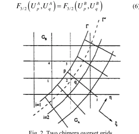
Take a consideration on Fig. 2. A common grid line Γ'
is drawn along
ξ
=
(
ξ ξ
1+
2) / 2
, where equation (4) is discredited. Suppose Γ' is fixed, as Δ→0 , mass conservation requires that
(
)
(
)
3/ 2 3/ 2
0 0
lim A, A lim B, B
p q j p q j
j j
F U U F U U F d
′ Γ
Δ→
∑
ΔΓ =′ Δ→∑
ΔΓ =′∫
Γ′(5) Where A
U
and BU
are the normal components of the contravariant velocities computed from the solution on gridA
G and GB respectively. Thus, the mass conservation condition is:
3/ 2
(
A,
A)
3/ 2(
B,
B)
p q p q
F
U
U
=
F
U
U
(6)Fig. 2. Two chimera overset grids
In order to transfer the solution information on grid B to grid A through the overlapping area, we use I
p
U
and I qU
to approximate Bp
U
and B qU
, respectively. We obtain
( )
( )
2
2
B I
p p
B I
q q
U
U
o
U
U
o
=
+ Δ
=
+ Δ
(7)By which, equation (6) gives rise to
(
)
(
) ( )
23/ 2
,
3/ 2,
A A I I
p q p q
F
U
U
=
F
U U
+ Δ
o
(8) Equation (8) is the general formation of MFBI algorithm for grid interfaces. Furthermore, by Taylor expansion of equation (8), it is obtained that( )
1, , 2, , 3/ 2, , 3/ 2, , ,1 3/ 2, , 1, , 3/ 2, , 2
,2 3/ 2, , 2, , 3/ 2, ,
(( ) ,( ) ) (( ) ,( ) ) | (( ) ( ) )
| (( ) ( ) )
j k j k j k j k j k j k j k
j k j k j k
U U U U U U
F F F
J J J J J J
U U
F o
J J
= + −
+ − + Δ
[image:2.595.321.547.320.537.2]
,1 3/ 2, ,
|
j k ,2 3/ 2, ,|
j k1/ 2
F
=
F
=
(10) Thus, equation (9) can be simplified( )
( )
( )
( )
1, , 2, , 3/ 2, , 3/ 2, ,
2
1, , 2, , 3/ 2, ,
2
3/ 2, , 3/ 2, ,
2 3/ 2, ,
1, , 2, , 2
3/ 2, ,
(( ) ,( ) ) (( ) ,( ) )
1(( ) ( ) 2( ) ) 2
(( ) ,( ) )
( )
2
j k j k j k j k
j k j k j k
j k j k
j k
j k j k
j k
U U U U
F F
J J J J
U U U
o
J J J
U U
F o
J J
U
o J
U U
o J
=
+ + − + Δ
= + Δ
= + Δ
+
= + Δ
(11)
Therefore, Eqs. (8) and (11) yield
( )
2 1, , 1, , 2, , 2, ,A I I A
j k j k j k j k
U =U +U −U + Δo (12)
Because
U
=
u
ξ
x+
v
η
x+
w
ζ
x, whereu
,v
,w
are three Cartesian components of the velocity, and by Taylor expansion, it is easy to verify that Eq. (12) can be guaranteed by1, , 1, , 2, , 2, , 1, , 1, , 2, , 2, ,
1, , 1, , 2, , 2, ,
A I I A
j k j k j k j k
A I I A
j k j k j k j k
A I I A
j k j k j k j k
u u u u
v v v v
w w w w
= + −
= + −
= + −
(13)
Thus, the complete formation of MFBI algorism can be formulated as
1, , 1, , 2, , 2, , 1, , 1, , 2, , 2, ,
1, , 1, , 2, , 2, ,
A I I A
j k j k j k j k
A I I A
j k j k j k j k
A I I A
j k j k j k j k
A I
p p
u u u u
v v v v
w w w w
p p
= + −
= + −
= + −
=
(14)
From equation (14), it can be seen that algorism MFBI makes modifications to the direct interpolation and just these modifications simultaneously grantee the global mass conservation and simple enforcement of the scheme.
III. NUMERICAL EXPERIMENT AND RESULTANTS
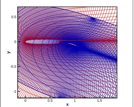
In order to validate and demonstrate capacities of the MFBI scheme, the flows around a multi-element airfoils NAWC1F2.2 under different conditions are considered. Boeing Company and NASA made lots of wind-tunnel experiments and obtained amount of aerodynamic experimental data about NAWC1F2.2, and related work can be found in Ref [21]. The flow solver for multi-element airfoils is composed of Reynolds-Averaged Navier-Stokes (RANS) equations, which are approximated by central-difference spatial scheme and five coupled Runge-Kutta time stepping scheme, and Boldwin-Lomax turbulence model. In order to accelerate the convergence and reduce oscillation in computation, local time stepping, implicit residual smoothing and carefully controlled artificial dissipative terms are also adopted in solver. For a complex flow about multi-element airfoils, the overlapping grids technique is set up. Each element grid is C-type and generated by partial differential equations. Fig. 3 and Fig.4 illustrate overlapping grids for the airfoils before and after hole cutting, respectively.
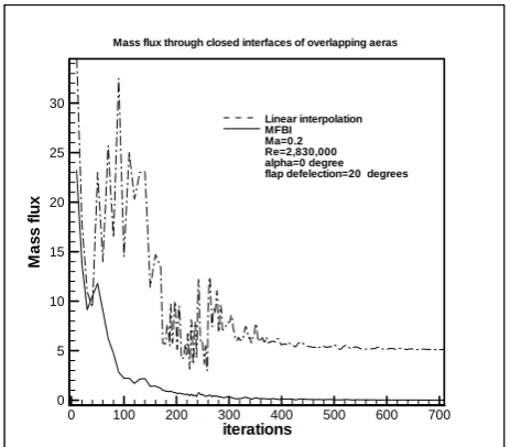
The pressure distribution along each element airfoil with different interpolations for the inflow Ma=0.2, Re=2,830,000 is displayed in Fig. 5. Numerical results about variation of lift coefficient versus angle of attack and relative experimental data are illustrated in Fig. 6. Fig. 7 gives polar lift curves of the airfoil NAWC1F2.2 with flap deflection 20 degrees. The calculated time histories for mass flux and velocity flux through closed interfaces Γa + Γb of overlapping areas are displayed in Fig. 8 and 9, respectively.
Considering the differences in Figs. 5-7 between non-conservative direct interpolation and mass conservative interpolation, it can be seen that the conservative scheme is more in agreement with the experimental data. Figs. 8 and 9 indicate that algorithm MFBI do not only grantee the attribution of the global mass conservation, but also ameliorate the moment conservation oscillations in computation. So for flows involving large solution gradients and strong elliptic effects, such as flows around multi-element airfoils which frequently exist large flow separation regions, the conservative scheme is more suitable.
x
y
0 0.5 1 1.5
[image:3.595.313.541.297.479.2]-1 -0.5 0 0.5
Fig. 3 overlapping grids for multi-element airfoils before hole cutting
x
y
0 0.2 0.4 0.6 -0.1
0 0.1
x
y
1 1.2 1.4 1.6 -0.2
-0.1 0 0.1
x/c
-C
p
-0.2 0 0.2 0.4 0.6 0.8 1 1.2 1.4
-2 -1 0 1 2 3 4 5 6
Validation of NAWC1F2.2 airfoil at alpha=0 with flap deflection 20 degrees
[image:4.595.305.544.46.503.2]Linear interpolation MFBI Experimental Ma=0.2 Re=2,830,000
Fig. 5 surface pressure distribution
ALPHA
CL
-10 -5 0 5 10
0.2 0.4 0.6 0.8 1 1.2 1.4 1.6 1.8 2 2.2 2.4 2.6
Linear interpolation MFBI
Experimental
NAWC1F2.2 DEFL=20 Re=2,830,000 Ma=0.200
Fig. 6 lift curves of NAWC1F2.2 DEFL=20
CD*10000
CL
200 400 600
0.5 1 1.5 2 2.5 3
Linear interpolation MFBI
Experimental
NAWC1F2.2 DEFL=20 Re=2,830,000 Ma=0.200
Fig. 7 polar curves of NAWC1F2.2 DEFL=20
iterations
Ma
s
s
fl
u
x
0 100 200 300 400 500 600 700
0 5 10 15 20 25 30
Mass flux through closed interfaces of overlapping aeras
Linear interpolation MFBI Ma=0.2 Re=2,830,000 alpha=0 degree flap defelection=20 degrees
Fig. 8 Mass flux through closed interfaces of overlapping areas
iterations
V
e
lo
ci
ty
fl
u
x
100 200 300 400 500 600 700
20 40 60 80 100 120
Velocity flux through closed interfaces of overlapping areas
[image:4.595.311.543.49.252.2]Linear interplotation MFBI2 Ma=0.2 Re=2,830,000 alpha=0 degree flap deflection=20 degrees
Fig. 9 Velocity flux through closed interfaces of overlapping areas
IV. CONCLUSION
In the present study, a lot of attentions are paid to an interface mass conservative algorism MFBI in a chimera girds flow solver. To assess the conservative attribution of the scheme, complex flows around a multi-element airfoil NAWC1F2.2 with a flap are calculated under different conditions. Related results indicate that algorism MFBI has not only better performances on convergence of solutions, conservation of both mass and moment flux in global domain but also better consistency of experimental results.
REFERENCES
[1].J. Cai, H.M. Tsai, F. Liu, An overset grid solver for viscous computations with multigrid and parallel computing, in: AIAA 16th Computational Fluid Dynamics Conference, Orlando, FL, 2003,AIAA Paper 2003-4232.
[image:4.595.308.546.271.487.2]heart valves: grid resolution and flow symmetry, ASME Journal of Biomechanical Engineering, 2003, in press. [3].L. Ge, J. Paik, S.C. Jones, F. Sotiropoulos, Unsteady RANS of Complex 3D Flows Using Overset Grids, in: Proceedings of the 3rd International Symposium on Turbulent and Shear Flow Phenomena, Sendai, Japan, 25–27 June 2003, vol. 1, pp. 67–68.
[4].Y.L. Lee, J.D. Baeder, High-order overset method for blade vortex interaction, in: AIAA 40th Aerospace Sciences Meeting, Reno, NV, January 2002, AIAA Paper 2002-0559. [5].Y.L. Lee, J.D. Baeder, Implicit hole cutting – a new approach to overset grid connectivity, in: AIAA 16th Computational Fluid Dynamics Conference, Orlando, FL, 2003, AIAA Paper 2003-4128.
[6].Lijewski L. Transonic mutual interference of wing-pylon multiple body configurations using an overlapping grid scheme [R] . AIAA Paper 93 - 3023 ,1993.
[7].Chan William M. Buning Pieter G. Surface grid generation methods for overset grids [J] . Computers &Fluids , 1995 ,24(5) :509 - 522.
[8].P.G. Buning, D.C. Jespersen, T.H. Pulliam, W.M. Chan, J.P.Slotnick, S.E. Krist, K.J. Renze, OVERFLOW User’s Manual,Version 1.8, NASA Langley Research Center, 1998. [9].Z.J. Wang, V. Parthasarathy, A fully automated chimera methodology for multiple moving body problems, Int. J. Numer. Meth. Fluids 33 (2000) 919–938.
[10].Benek, J. A., Sterger, J. J. and Dougherty, F. C., A flexible grid embedding technique with application to the Euler equations. AIAA-83-1944-CP, 1983.
[11].Rai, M. M., A implicit, conservative, zonal-boundary scheme for Euler equation calculations. AIAA-85-0488, 1985.
[12].Berger, M. J., On conservation at grid interfaces. SIAM J. Numer. Anal., 1987, 24, 5, 967-984.
[13].J. Liu, W.SHYY, assessment of grid interface treatment for multi-block incompressible viscous flow computation,J. Comp. Fluids, 1996, 25, 719-740.
[14].W.D. Henshaw, A fourth-order accurate method for the incompressible Navier–Stokes equations on overlapping grids,J. Comput. Phys. 113 (1) (1994) 13–25.
[15].H.S. Tang, Study on a grid interface algorithm for solutions of incompressible Navier–Stokes equations, J. Computers Fluids 2006 35:1372–1383
[16].Part-Enander, E. and Sjogreen, B., Conservative and non-conservative interpolation between overlapping grids for finite volume solutions of hyperbolic problems. Comp. Fluids, 1994, 23, 551-574.
[17].Z.J. Wang, A fully conservative interface algorithm for overlapped grids, J. Comput. Phys. 122 (1995) 96–106. [18].Tang HS, Jones SC, Sotiropoulos F. An overset grid method for 3D unsteady incompressible flows. J Comput Phys 2003;191:567–600.
[19].H.S. Tang, Numerical simulation of unsteady three dimensional incompressible flows in complex geometries, Ph.D. dissertation, School of Civil and Environmental Engineering, Georgia Institute of Technology, Atlanta, GA 30332–0355, 2001
[20].B. Hubbard, H.C. Chen, A Chimera scheme for incompressible viscous flows with application to submarine hydrodynamics,AIAA Paper 94-2210 (1990).