TM
.,NTCRFACCR
3.
TECHNICAL MANUAL
IEEE 696 / S-100
8 CHANNEL SERIAL
1/0
BOARD
RS232 • with full handshake
r
®
TABLE OF CONTENTS
About Interfacer 3 • Technical overview • •
Port map • • • • • • • • • • Port addressing
User/board selection • Wait state selection •
Cables • • • • • •
Slave clear/power-on-clear option Using interrupts • •
Channel 6/7 interrupt option Interrupt control registers Interrupt status registers •
.
.USART initialization • • • • • • • • Data registers • • • • • •
Status register • • • • •
Mode registers • • • •
Command register • • • • • • Serial mode jumpers
RS-232 control lines
Synchronous mode clock driver/receivers Theory of operation
S-100 Bus drivers I/O port decode logic Strobe generation logic Wait state logic • • • •
Interrupt control/status logic USARTs • • •
RS-232 level conversion logic User notes • • • • • • • Sample test programs
Asynchronous mode Synchronous mode • • CP/M console • •
INS2651 Programmable Communications Interface Logic diagram • • • •
USARTs 0 - 7 (detail) Parts list • • •
Component layout • • • • • • •
Customer service/limited warranty information
3 3 4 4 5
6
6 7 8 8 9 9
10 11 11 12 13 13 14 14-15 16 16 16 17 17 17
18 18 19
• 20-21 • 22-23 • 24-25 • • 26-31 • 32-33 34-37
38
39 40
--- DISCLAIMER ---Godbout Electronics makes no representations or warranties
with respect to the contents hereof and specifically
disclaims any implied warranties of merchantability or
fitness for any particular purpose. Further, Godbout
Electronics reserves the right to revise this publication and to make any changes from time to time in the content hereof without obligation of Godbout Electronics to notify any person of such revision or changes.
ABOUT INTKRFACKR. 3
Congratulations on your decision to purchase the INTERFACER 3 multi-user serial I/O board. INTERFACER 3 has been designed to be the most flexible and highest performance multi-user serial I/O interface available that fully complies with the IEEE 696/S-100 bus standard. Due to its provision for ready expansion and modification as the state of the compu-ting art improves, the S-100 bus is the professional level choice for commercial, industrial, and scientific applications. We believe that this board along with the rest of the S-100 portion of the CompuPro family, is
one of the best boards available for that bus.
The INTERFACER 3 boasts several innovative features not found on
currently available multi-user I/O boards. These features include 8 fully programmable asynchronous serial channels, 2 of which are capable of high speed synchronous transmission, five RS-232 handshaking lines per channel plus bi-directional clock drivers on both the synchronous channels, expan-dability to 32 users with four boards using only 8 port addresses, a flexible interrupt structure with full maskability and pending status on both transmit and receive interrupts, and conservative design for operation with most CPUs operating at up to 10 MHz. Other features standard to all CompuPro boards include thorough bypassing of all supply
lines to suppress transients, on-board regulators, and low power Schottky TTL and MaS technology integrated circuits for reliable, cool operation. All this and sockets for all IC's go onto a double sided, solder masked printed circuit board with a complete component legend.
TECHNICAL OVERVIEW
The INTERFACER 3 was designed primarily for operation in interrupt
driven/ multi-user microcomputer systems. Sixteen distinct interrupts are generated on-board by the eight USARTs, and these are brought out for jumpering by the user to the eight vectored interrupt lines on the S-]OO bus. Since these interrupt lines are open collector, they may be configured to interrupt on any or all of the vectored interrupt lines. In addition, a transmit and receive interrupt mask port is provided for inhibiting unwanted interrupts.
The INTERFACER 3 provides multi-user operation with a m~n~mum number
of I/O ports by incorporating a user select register to activate the required serial channel. The five bit register is used to select a parti-cular serial channel, which allows up to 32 users (four boards) on t~e
same 8 port addresses. When a particular user is selected, the four USART registers associated with that specific serial channel are made available for examination and alteration by the host processor or other temporary bus master. In addition, whenever a particular channel is selected, the interrupt registers on that particular board are available for examination and alteration.
The typical sequence of operation would require all channels on the
INTERFACER 3 to be mode initialized and the interrupt mask registers set
interrupt status registers may be polled and checked in roughly the same manner as a standard single channel serial board.
Six of the serial channels on the INTKRFACER 3 are designed for direct connection to DATA TERMINAL EQUIPMENT (DTE) in asynchronous mode without alteration of the cables. This allows direct connection to CRT terminals and printers. The remaining two channels may be connected in either DTE
mode or DATA COMMUNICATION EQUIPMENT (DCE) mode. This allows direct
connection to all types of RS-232 equipment including modems. In
addi-tion, these two channels are capable of high speed synchronous operation using internal or external clocks.
PORT MAP
The INTERF ACER 3 in t e r f ace use s a b lo c k 0 f e i g h t po r tad d res s e s for communication between it and the host processor. The address of the first port is switch selectable to any address which is a multiple of eight. The ports will be referred to as relative ports 0 - 7.
RELATIVE PORT
o
1
2
3
4
5
6
7
PORT ADDRESSING
FUNCTION
USART Data Register (R/W)
USART Status Register (R) SYN1/SYN2/DLE Register (W)
USART Mode Register (R/W)
USART Command Register (R/W)
Transmit Interrupt Status Register Transmit Interrupt Mask Register
Receive Interrupt Status Register Receive Interrupt Mask Register
Not used
User Select Register (write only)
(R)
(W)
(R)
(W)
DIP switch Sl, positions 1 thru 6 are used to select the base address of the eight port block in a binary fashion as shown below:
SWITCH POSITION
1 • 2 •
ADDRESS BIT
• PORT DISABLE WHEN
• • • • • A7 • • • • • A6
A5
3 •
4 •
5 •
6 •
• • • • • • • A4
• A3
"ON"
EXAMPLE: To address this board at addresses lOR thru 17R for the CompuPro-/Phase 1 OASIS operating system, position 1 and 5 would be "OFF" and positions 2 thru 4 and positions 6 would be "ON".
EXAMPLE: To address this board at addresses 38R thru 3FR, positions 1, 4, 5, and 6 would be "OFF" and positions 2 and 3 would be "ON".
USER/BOARD SELECTION
To select a particular channel and to select which board that channel will be on (when running more that 8 users), requires the use of the User
Select Port and two board select switches. The five bit User Select
Register determines which of 32 possible users will be selected at a particular time. The two board select switches determine whether a board will respond to users 0 thru 7, 8 thru 15, 16 thru 23, and 24 thru 31. A particular user (0-31) is selected by outputting the five bit number that represents that user. The diagram shown below will describe the relation between the board select switches and the User Select Register.
USER SELECT REGISTER
DATA BIT NAME FUNCTION
DO USO USER SELECT 0 (LSB)
D1 US1 USER SELECT 1
D2 US2 USER SELECT 2 (MSB)
D3 BSO BOARD SELECT 0 (LSB)
D4 BS1 BOARD SELECT 1 (MSB)
D5 NOT USED
D6 NOT USED
D7 NOT USED
Since each INTERFACER 3 will support 8 users, we will refer to these 8 as RELATIVE USER 0-7. These 8 ports are physically configured with rela-tive user 0 on the extreme right side of the board and relarela-tive user 7 on the extreme left side. To determine the exact user number, the RELATIVE USER number must be added to the USER OFFSET number. The RELATIVE USER number corresponds to the 3 bits above called USER SELECT 0-2, and the USER OFFSET number corresponds to the 2 bits above called BOARD SELECT 0 and 1. These 5 bits determine the exact user number.
RELATIVE
US2 US1 USO USER NUMBER
0 0 0 USER 0
O· 0 1 USER 1
0 1 0 USER 2
0 1 1 USER 3
1 0 0 USER 4
1 0 1 USER 5
. BOARD BOARD USER
SELECT SWITCHES SELECT BITS OFFSET
Sl-8 Sl-7 BS1 BSO
ON ON 0 0 0
ON OFF 0 1 8
OFF ON 1 0 16
OFF OFF 1 1 24
EXAMPLE: To address the INTERFACER 3 to respond to users 0 thru 7,
switches Sl-7 and Sl-8 would be "ON". To select a particular user in the group from 0 to 7, BS1 and BSO must be "0" for the board to respond. To select user 5, a 05H must be sent to the user select port.
EXAMPLE: To iddress the INTERFACER 3 to respond to users 16 thru 23~
switch Sl-7 would be "ON", and switch Sl-8 would be "OFF". To select a particular user in the group from 16 to 23, BS1 must be a "1" and BSO must be "0" for the board to respond. To select user 18, a 12H must be sent to
the user select port. .
WAIT STATE SELECTION
The INTERFACER 3 was designed to run in very fast microcomputer systems by allowing up to two wait states to be added when accessing the USART regis terse Since the user selec t and interrupt cont rol regis ters are capable of higher speed opera tion than the USART regis ters, no wai t states are inserted even when they are enabled on the board.
The 3 vertical p ins at J 17 control the enab ling of one or two wai t states. With the black pin shunt ~onnecting pins "A" and "C", one wait state will be inserted. With the pin shunt connecting pins "B" and "C", two wait states will be inserted. If the pin shunt is left removed, no wait states will be inserted.
CABLES
The INTERFACER 3 is designed to use two each of 2 different cables
assemblies. Relative users 0-5 use a custom 50 conductor cable and
relative users 6 and 7 use standard 26 conductor cables identical to those used on the INTERFACER 1 and INTERFACER 2.
Relative users 0-2 (50 pin connector on the far right) and relative users 3-5 (50 pin connector in middle of board) use a custom 3 user cable (see photo A page 7). This cable consists of a female 50 pin insulation displacement connector that splits into thirds and connects to three female DB-25 connectors. The actual cable has positions 1-16 (pin 1 on the far left side of the connector) on the first DB-25, positions 17-32 on the
second DB-25, and positions 33-50 on the third DB-25. NOTE: The pin
numbers on the circuit diagram show the pin numbers on the DB-25 connector and not the 50 pin connector.
(see photo B below). This cable consists of a female 26 pin insulation displacement connector that mates to a female DB-25 (the 26th conductor is not used). NOTE: The pin numbers on the circuit diagram show the pin numbers on the DB-25 connector and not the 26 pin connector.
SLAVE CLEAR/POWER-oN-CLEAR OPTION
USING INTERRUPTS
The INTERFACER 3 has a simple but elegant interrupt structure that allows considerable flexibility. Each USART generates both a transmit and receive interrupt, for a total of 16 distinct interrupts for the board. A transmit interrupt indicates that the USART transmit register is empty and it is ready to accept a character. A receive interrupt indicates that data is available from the receiver data register. Each of these inter-rupts may be masked "OFF" or "ON" by altering the INTERRUPT CONTROL
REGISTERS as described below. Each of these interrupts are open
collector, and may be individually tied to any of the 8 vectored interrupt
lines (VIO-VI7). The status of each interrupt line may be sampled by
reading the INTERRUPT STATUS REGISTERS as described below.
Since each of the 16 interrupts generated on the INTERFACER 3 may be tied to any of the 8 vec tored lines, almost any type of priori ty scheme may implemented. All transmit interrupts are brought out on one side of jumper socket J15, and all receive interrupts are brought out on one side of jumper socket J16. On the opposite side of each socket, each of the 8 vectored interrupt lines are brought out. By using the provided headers, any USART interrupt may be connected to any VI line. The pin-out of J15 and J16 are shown below.
INTERRUPT J15 VI LIRE 316 IRTERB.UPT
TxINT a 19 81 VIa 19 81 RxINT a
TxINT 1 110 71 VII 110 71 RxINT 1
TxINT 2 111 61 VI2 111 61 RxINT 2
TxINT 3 112 51 VI3 112 51 RxINT 3
TxINT 4 113 41 VI4 113 41 RxINT 4
TxINT 5 114 31 VIS 114 31 RxINT 5
TxINT 6 115 21 VI6 115 21 RxINT 6
TxINT 7 116 11 VI7 116 11 RxINT 7
---
---EXAMPLE: If we wish to generate an interrupt on vectored interrupt line VI3 when data becomes available from relative user 6, a wire should be soldered between pins 2 and 12 of J16.
EXAMPLE: If we wish to generate an interrupt on vectored interrupt line VI6 when data becomes available from relative users 0, 1, 2, and 7, a wire should be soldered to connect pins 1, 6, 7, 8 and 15 of J16.
EXAMPLE: If we wish to generate an interrupt on vectored interrupt line VIa when relative user 2 is ready to accept a character, a wire should be soldered to connect pins 8 and 11 of J15.
CHANNEL 6/7 IRTERB.UPT OPTION
Relative channels 6 and 7 are capable of generating a third interrupt
called TxEMT/DSCHG*. This interrupt occurs when the transmitter has
The TxEMT/DSCHG* output from the 2651 may be jumpered to generate either a transmit or receive interrupt. Due to the wire-QR capability of the interrupt outputs from the 2651, when jumpered, the transmit interrupt will become TxRDY OR TxEMT /DSCHG or the receive interrupt will become RxRDY OR TxRDY/DSCHG. Therefore, when jumpered, the user must check the status register to determine what condition caused the interrupt.
The following table will demonstrate where to install the shorting plug to generate the appropriate interrupt.
CHANNEL NUMBER
TO CAUSE A TxEMT/DSCHG INTERRUPT ON THE:
6 7
INTERRUPT CONTROL REGISTERS
TxRDY LINE RxRDY LINE
INSTALL J14 INSTALL J4
INSTALL J13 INSTALL J3
Two registers are provided for individually masking the transmit and receive interrupts from the bus. On power-up or reset, all interrupts are disabled on the INTERFACER 3. To gain' access to these registers, a user channel must be enabled on the particular board to be altered. (You cannot alter any interrupt register on the board set for users 0 thru 7 unless you have selected one of those 8 users) To enable a particular Transmit or Receive interrupt, a "1" must be sent to the proper bit of the register. The registers are configured so that Data Bit 0 will mask relative user 0, D1 will mask relative user 1, and so on with D7 masking relative user 7. This is true for both the Transmit Interrupt Control Register (relative port 4) and the Receive Interrupt Control Register
(relative port 5).
EXAMPLE: To enable all Transmit interrupts on a particular INTERFACER 3, you should send a OFFH to relative port 4.
EXAMPLE: To enable the transmit interrupt on relative users 1, 4 and 6, you should send a 52H to relative port 4.
EXAMPLE: To disable all Receive interrupts on a particular INTERFACER 3, you should send a OOH to relative port 5.
EXAMPLE: To enable the Receive interrupt on relative users 2, 3 and 7, you should send a 8CH to relative port 5.
INTERRUPT STATUS REGISTERS
The registers are configured so that Data Bit 0 contains the status of relative user 0, Dl contains the status of relative user 1, and so on with D7 containing the status of relative user 7. This is true for both the Transmit Interrupt Status Register (relative port 4) and the Receive
Interrupt Status Register (relative port 5). Remember, these status
registers are read only! Writing into these registers will alter the
Interrupt Control Mask. In addition, the status of a channel's interrupts are available even if those interrupts are masked "OFF". The Interrupt Control Register does not affect the reading of the status from a register.
EXAMPLE: If all Transmit interrupts on a particular INTERFACER 3 are
asserted, you will read a OFFH at relative port 4.
EXAMPLE: If transmit interrupts are pending on relative users 1, 4 and 6, you will read a 52H from relative port 4.
EXAMPLE: If there are no Receive interrupts pending on a particular IRTER-FACER 3 (no data available), you will read a OOH from relative port 5.
EXAMPLE: If Receive interrupts are pending on relative users 2, 3 and 7, you will read a BCH from relative port 5.
USART INITIALIZATION
The serial channels on the INTERFACER 3 are implemented with a 2651
type USART from either National Semiconductor or Signetics. Several of
the USART parameters and channel control functions are programmed by writing into or reading from certain registers in the 2651. They are:
1. The baud rate. 2. The word length.
3. Whether or not a parity bit is generated.
4. Whether the parity is even or odd (if generated). 5. The number of stop bits.
6. Enabling and disabling the transmitter and receiver. 7. Setting and testing the RS-232 handshake lines.
B.
Synchronous or asynchronous operation.In addition, the normal status indication and data transfer functions are also handled through the USART's registers.
A table of the various registers and where they appear in the I/O port map is shown in a previous section and in the following tables.
"READ" or "INPUT" Ports
Relative Port Address
00 hex 01 hex 02 hex 03 hex
UART Register Function
''WRITE'' or "OUTPUT" Ports
Relative Port Address
00 hex 01 hex 02 hex 03 hex
UART Register Function
Data port, write transmit data.
SYN1/SYN2/DLE register, write sync bytes. Mode registers, write mode bytes.
Command register, write command byte.
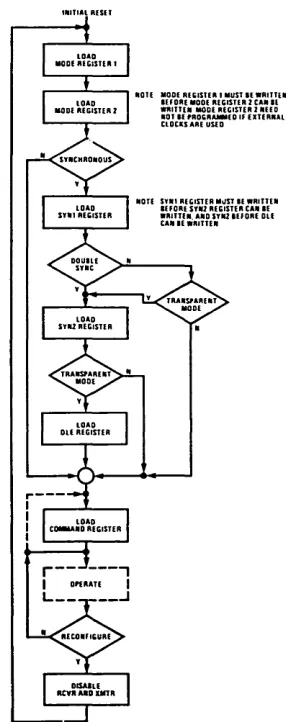
USART INITIALIZATION SEQUENCE
When bringing up the USART in asynchronous mode, the following sequence of events must occur:
1. Set Mode Register 1 2. Set Mode Register 2 3. Set Command Register
4. Begin normal USART operation
When bringing up the USART in transparent synchronous mode, all of the following sequence of events must occur. If bringing up the USART in non-transparent synchronous mode, step 5 may be omitted.
1. Set Mode Register 1 2. Set Mode Register 2 3. Set SYN1 Register
4. Set SYN2 Register 5. Set DLE Register 6. Set Command Register
7. Begin normal USART operation
DATA REGISTERS
The UART data registers are straight-forward in their operation. You write a byte to the data register when you want to transmit that byte to an external serial device and you read the byte in the data register to receive a byte from an external serial device. The UART will automatically add the proper start and stop bits when transmitting and will remove them when receiving.
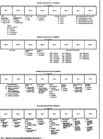
STATUS REGISTER
The status register is used to determine the current state of the UART. Each bit of the status register has a different meaning depending on whether it is high or low. (High means a logic one or high level and low
means a logic zero or low level.) The following table describes the
SR-7 SR-6 SR-S
DATASET DATA CARRIER FEISYN DETECT READY DETECT
ASYN; 0-1m! INPUT 0: DCD INPUT
0- NORMAL ISHIGH IS HIGH
1-1m! INPUT 1 = DCO INPUT l ' FRAMING ERROR IS LOW IS LOW SYNC;
0- NORMAL 1 • SYN CHARACTER
DETECTED
STATUS REGISTER FORMAT
SR-4
OVERRUN O' NORMAL 1 = OVERRUN
ERROR
BIT NUMBERS
SR-3
PE/DLE DETECT ASYNC; 0= NORMAL 1 = PARITY ERROR SYNC; O· NORMAL 1 - PARITY ERROR
OR OLE CHARACTER RECEIVED
SR-2 SR-l
TxEMT/DSCHG RxRDY O' NORMAL O' RECEIVE
HOLDING 1 • ~NGE~ REGISTER
fR~NO~IT SH~~ EMPTY REGISTER IS l ' RECEIVE EMPTY HOLDING
REGISTER HAS DATA
SR-O TxRDY O'TRANSMIT HOLDING REGISTER BUSY 1- TRANSMIT HOLOING REGISTER EMPTY
NOTE 1; BAUD RATE FACTOR IN ASYNCHRONOUS MODE APPLIES ONLY IF EXTERNAL CLOCK IS SELECTED. FACTOR IS 16x IF INTERNAL CLOCK IS SELECTED.
MODE REGISTERS
W hen b r in gin g up the U AR T, its two mod ere g i s t e r s m u s t be set wit h
various bit patterns that will determine the operating modes. There are
two registers, however they occupy only one I/O port address. This is accomplished with internal sequencing logic that allows you to write the first register (Mode Register 1) and then the second register (Mode Register 2). It is important to write to Mode Register 1 first.
The meanings of the various bits in the mode registers are described below:
MRI-7 MRI-6
SYNC; NO. OF SYN CHARACTERS
SYNC; TRANSPARENCY CONTROL O' DOUBLE SYN
l ' SINGLE SYN
O' NORMAL 1 • TRANSPARENT ASYNC;
STOP BIT LENGTH 00' INVALID 01 • 1 STOP BIT 10' 11'> STOP BITS 11' 2 STOP BITS
MR2-7
NOT USED MRI-6
MR1-S
PARITY TYPE O· ODD 1· EVEN MR2-S TRANSMITTER CLOCK O· EXTERNAL , . INTERNAL
MODE REGISTER 1 FORMAT
BIT NUMBERS
o ..
~
I MRI-3 MRI-2PARITY CONTROL CHARACTER LENGTH 0- DISABLED
l ' ENABLED
00 - S BITS 01' 6 BITS 10' 7 BITS 11 • 8 BITS
MODE REGISTER 2 FORMAT
OA2~
.IT"l"AS .A'.'
MR2-2
0 .. ·'
I
.A'-IMODE AND BAUD RATE FACTOR' 00' SYNCHRONOUS Ix RATE 01' ASYNCHRONOUS Ix RATE 10' ASYNCHRONOUS 16x RATE 11 • ASYNCHRONOUS 64x RATE
MR2-1 MR2-O
RECEIVER CLOCK
BAUD RATE SELECTION 0= EXTERNAL
1 • INTERNAL
0000 = SO BAUD 0001 = 7S BAUD
0110' 600 BAUD 0111 = 1200 BAUD 0010 =·110 BAUD 1000 = 1800 BAUD 0011 = 134.S BAUD 1001 = 2000 BAUD 0100· ISO BAUD 1010 = 2400 BAUD 0101 = 300 BAUD 1011 = 3600 BAUD
1100·4800 BAUD 1101' 1200 BAUD 1110' 9600 BAUD 1111=19200 BAUD
That completes the description of the Mode Registers. Remember that
COMMAND REGISTER
The Command Register is used to set the operating mode (sync or async), enable or disable the receiver and/or transmitter, force a "break" condition, reset the error flags and control the state of the RTS and DTR outputs.
CR-7 CR-6
OPERATING MODE 00' NORMAL OPERATION 01' ASYNC: AUTOMATIC
ECHO MODE SYNC: SYN AND/OR OLE STRIPPING MODE 10' LOCAL LOOP BACK 11 • REMOTE LOOP BACK
SERIAL MODE JUMPERS
CR-S
REQUEST TO SEND O' FORCES rn
OUTPUT HIGH 1 = FORCES rn
OUTPUT LOW
COMMAND REGISTER FORMAT
BIT NUMBERS
CR"
I
CR-JRESET ERROR O' NORMAL
ASYNC: FORCE BREAK 1 = RESET ERROR O' NORMAL
~~~M~~~n~s 1 = FORCE BREAK
OE. PE/DLE SYNC: DETECT)
SEND OLE 0= NORMAL 1 = SEND OLE
CR-2
RECEIVE CONTROL (RxEN) 0= DISABLE 1 • ENABLE
CR-l
DATA TERMINAL READY O' FORCES DTR
OUTPUT HIGH 1 = FORCES DTR
OUTPUT LOW
CR-O
TRANSMIT CONTROL 0= DISABLE 1 = ENABLE
The INTKRFACER 3 board with its serial programming jumpers allows the user to adapt relative channels 6 and 7 to all standard RS-232 pin configurations. In RS-232 mode, these jumpers may be set so that this board operates in a "master" mode where i t behaves as the Data Terminal Equipment (DTE), or i t may be set so that the board operates in a "slave" mode where it behaves as the Data Communication Equipment (DCE). Since almost all CRT terminals and serial interface printers operate as the "master" or as the Data Terminal Equipment, then the INTERFACER 3 board must operate as the "slave" or Data Communication Equipment. (For this reason, relative channels 0 - 5 are set to operate in this mode.) For example, to connect the INTERFACER 3 to a terminal like an Televideo or a Hazeltine, relative channels 0 - 5 will connect directly and relative channels 6 and 7 require that serial mode jumpers (J1 and J2) should be set in "slave" mode as shown on the following table. To connect relative channels 6 and 7 to a Modem is a different set-up because Modems are set to operate as "slaves". When connected to a Modem, the serial mode jumpers (J1 and J2) of the INTERFACER 3 should be set in the "master" mode as shown on the following table.
PROGRAHHING JUMPERS
SLAVE MODE, J1/J2: for connections to CRT term-inals, printers, etc.
1--- - I
RS-232C CONTROL LINES
The RS-232 control and data lines are defined as shown below. The EIA RS-232 standard defines a signal line at greater than +3V (+12V typical) to be "SPACING" and a signal line at less than -3V (-12V typical) to be "MARKING".
PINI CIRCUIT DIR. NAKE DESCRIPTION
1 AA PROTECTIVE GROUND
2 BA TO DCE TxD TRANSMITTED DATA
3 BB TO DTE RxD RECEIVED DATA
4 CA TO DCE RTS REQUEST TO SEND
5 CB TO DTE CTS CLEAR TO SEND
6 CC TO DTE DSR DATA SET READY
7 AB SIGNAL GROUND
8 CF TO DTE DCD REC'D LINE SIGNAL DET.
15 DB DCE SOURCE TSET TRANS. SIG. ELE. TIMING
17 DD DCE SOURCE RSET REC'D SIG. ELE. TIMING
20 CD TO DCE DTR DATA TERMINAL READY
Five hardwired RS-232 handshaking signals are provided for interfacing to equipment needing these lines as shown below. Output lines may be set either "MARKING" or "SPACING" and their state may be altered by software commands as described in the USART INITIALIZATION Section under Command Register.
NAME DTR RTS
NAME DSR CTS DCD
OUTPUT LINES
RS-232 LINE CD
CA
DB25 PIN CONNECTION 20 OR 6
*
4 OR 5
*
INPUT LINES
RS-232 LINE CC
CB CF
DB25 PIN CONNECTION 6 OR 20
*
5 OR 4
*
8*
NOTE: Non-starred pin numbers indicate the DB25 pin number for relative channels 0 - 5 and when the Serial Mode Jumpers of relative channels 6 and 7 are set for "master" mode. The starred pin numbers indicate the DB25 pin number on relative channels 6 and 7 when the Serial Mode Jumpers are set f or "slave" mode.SYNCHRONOUS MODE CLOCK DRIVER/RECEIVERS
Relative channels 6 and 7 can either transmit or receive the synchronous signal timing element signals. The typical configuration requires that the DATA COMMUNICATION EQUIPMENT (DCE) be the source of the
capable of independently transmitting or receiving either of the clocks in either DCE or DTE modes. The following table will describe how the pin shunts should be set for transmitting or receiving the clocks.
I
CHANNELI
NUMBER6
7
RECEIVE SYNC CLOCK TRANSMIT SYNC CLOCK
TRANSMIT RECEIVE TRANSMIT RECEIVE
INSTALL JII
I
INSTALL JI2I
INSTALL J9I
INSTALL JI0I
INSTALL J7
I
INSTALL J8I
INSTALL J5I
INSTALL J6EXAMPLE: If you want relative channel 7 to transmit both its transmit and receive sync clocks, you would install pin shunts on J7 and JS.
THEORY OF OPERATION
The INTERFACER 3 can be roughly divided into 7 subsections for
describing its operation. These sections include: The S-100 Bus Drivers, the I/O Port Decode Logic, the Strobe Generation Logic, the Wait State Logic, the Interrupt Control/Status Logic, the USART, and the RS-232 Level Conversion Logic.
S-100 BUS DRIVERS
The separate data input and output data buses of the S-100 bus are converted to a bi-directional data bus by octal drivers U44 and U58. Data from the S-100 bus is driven onto the internal data bus by U58 only when sOUT goes high, indicating an output operation. The internal data bus is driven onto the S-100 bus when DOEN* goes low, indicating that a valid board select (SEL) and pDBIN are high (NAND-U45).
All S-100 bus signals are buffered onto the board if the line would otherwise have more than 1 LSTTL load. Address lines AO, AI, A2, and pDBIN are buffered onto the board by 2/3 of hex buffer U48, and the lines sOUT, sINP, pWR*, ~, and pSTVAL* are inverted using portions of U29, U43, and U50.
I/O PORT DECODE LOGIC
The eight port block that the INTERFACER 3 occupies is decoded by 6 open collector X-OR gates (U46 and U47). 5 of these gates decode address lines A3-A7 by comparing against positions 2-6 of switch Sl, and the last section compares sOUT and sINP* to determine if an I/O operation is occu-ring. When all compare conditions are satisfied, ASEL goes high. Closing position 1 of SI will ground ASEL and disable the board completely.
A valid board select (SEL*) is generated (by 1/3 of U32), when ASEL goes high along with USEL (indicating that this boards select number is active) and Al and A2 are not both high (indicating the USER SELECT PORT is not selected). SEL* is disabled by 1/3 of U32 when the USER SELECT PORT is enabled so that conflicts between up to four boards does not occur.
A USER SELECT write occurs when ASEL, Al, A2, sOUT, and STROBE go high. This generates OUTO* (U32) which clocks the least significant 5 bits on the bus (DO-D4) into hex latch U34. The 3 low order bits of U34 are decoded into 8 chip enables (CEO* - CE7*) by U35 when SEL is high and A2 and ESTROBE* are low. The 2 high order bits of U34 are compared to switch positions 7 and 8 of SI by 1/2 of U47 (X-NOR) to decode a current user board select signal USEL. Access to registers on the board requires that USEL be high before access is gained.
STROBE GKNKKATION LOGIC
In order to gain additional access time in an I/O cycle for the 2651 USARTs, the INTERFACER 3 generates early strobes based on valid status. S-100 bus strobes pDBIN and pWR* are gated together (U30) and inverted to generate STROBE and STROBE*. These signals indicate that a bus strobe is occuring. The interrupt registers and user select port have their data gated by STROBE because they are TTL and capable of very high speed operation. Since the 2651 type USART is a MOS device and has an access time of approximately 250 nS, an early strobe is generated so that wait
states are avoided whenever possible. A status valid signal, ESTATVAL*,
is generated whenever pSYNC is high and pSTVAL* is low. ESTATVAL* clears "0" flop U33a to generate ESTROBE*, which becomes one term of the USART chip enable decoder U35. The termination of STROBE* causes a "1" to be clocked into U33a and terminate ESTROBE*.
WAIT STATE LOGIC
To allow operation with high speed processors, a wait state generator
allows the addition of 1 or 2 wait cycles. U31 forms a 2 bit shift
register clocked by 4>*. A wait state is left pending after STROBE goes low, and when STALL1* or STALL2* and A2 are low (U30), and SEL is high (U45), WAIT* is generated. STALL1* is clocked out on the next rising edge of ~* after STROBE goes high, and STALL2* is clocked out the following cycle. The pRDY* line is pulled low by U48 when WAIT* goes low. When neither STALL 1 * or STALL2* is connected on J 17, no wait states will be generated.
INTERRUPT CONTllOL/STATUS LOGIC
The interrupt logic consists of two 8 bit latches for enabling inter-rupts onto the bus, two 8 bit buffers for reading current interrupt status, and sixteen 2 input open collector NAND buffers for driving the interrupts on the bus.
Two 8 bit latches are formed by four 4 bit latches (U38, U41, U52, and U55) for generating the interrupt enable mask. The
Q
outputs become the RxINTENx and TxINTENx interrupt enables for selectively masking "OFF" individual interrupts. Upon power-up or reset, these latches are cleared by CLR* so that all interrupts are disabled.The TxRDY and RxRDY interrupt outputs from the 2651 USARTs are
inverted to form active high interrupt signals. These interrupt signals
are fed to one input of the open collector NAND buffer, with the
corres-ponding interrupt enable fed to the other input. The resulting interrupt
outputs (TxINTx and RxINTx) are capable of driving the VIO-7 lines directly, and are brought out to J15 and J16 for jumpering to the appro-priate line.
Relative channels 6 and 7 allow jumpering the TxEMT/DSCHG interrupt from the USART to either the TxRDY or RxRDY interrupt outputs. This is possible since the outputs from the 2651 are open drain and may be wire-ORed.
USARTS
The 2651 type USART is quite sophisticated in that it can run in both asynchronous as well as synchronous modes. In addition, the part has an internal baud rate generator, RS-232 status and control bits, up to 3 interrupt outputs, and the capability of transmitting as well as receiving baud clocks.
The chip enable (CE) and read/write (R*/W) lines are operated by initially determining whether a read or a write will occur (sINP* to R*/W) and then strobing the part with CE*. Address lines AO and Al determine which of four registers will be selected and CLR resets the USART.
The baud rate clock BAUDCLK is generated by a 5.0688MHz crystal oscil-lator formed from 3 inverters (U29) and crystal Xl.
RS-232 LEVEL CONVERSION LOGIC
Each USART has a full compliment of RS-232 handshaking lines for devices that require them. Industry standard 1488 and 1489 receivers and transmitters are used throughout for highest performance. In addition to the data lines TxD and RxD, each channel has a RTS and DTR output and a
CTS, DSR, and DCD input. All three RS-232 status lines have pullup
resistors to +12V so that floating inputs are pulled high.
Relative channels 0 - 5 have the RS-232 lines set for direct connec-tion to CRT terminals and printers. Relative channels 6 and 7 may be set for both DCE and DTE modes by wiring new jumpers for Jl and J2.
SAMPLE TEST PROGRAM FOR RUNNING IN ASYNCHRONOUS MODE
*
*
*
*
*
INTERFACER 3 TEST PROGRAM
*
This program will initialize all 2651s for asynchronousoperation at 9600 baud with 8 data bits, one stop bit, no parity. This program will echo all characters received on any user channel (from 0 to 31) and if any user sends a ~C, the program will terminate and return back to CP/M.
NOTE: This program assumes that the console device is either an INTERFACER 1 or 2 addressed at ports 0 and 1.
*
*
base udata ustat mode commr txreg rxreg user exit tbmt dav*
*
*
Start Loop Init Echo Loop1 equ equ equ equ equ equ equ equ equ equ equ org mvi inr cpi jz out mov call mov jmp mvi out mvi out mvi out ret mvi out out inr out mov call 18h BASE+Oh BASE+1h BASE+2h BASE+3h BASE+4h BASE+5h BASE+7h 0 01h 02h 100h a,Offh a 20H echo user b,a init a,b loop a,OCEh mode a,7Eh mode a,27h commr a,OFFh txreg rxreg a user b,a cstat;data port in and out ;status register port ;mode register port ;command register port ;tx int register
;rx int register ;port to select user ;CP/M reentry point
;transmitter buffer empty ;data available
;init user ;next user
;check for final uart ;start echo routine ;select uart
;save user in b ;init the uart ;restore user ;next
;set up the 2651
;send to mode register 1 ;9600 baud, internal clocks ;SEND BYTE TO M.R. 2
;could be 07h (no 1420)
cpi OAAh jdata if aa
cz ok jdo echo loop
mov a,b ;restore user
jmp loop! jnext
Ok call inloop jget data
call oloop ;output data
ret
Cstat in ustat ;look for key entry
ani dav jcheck status
jz nodat ;no data
mvi a,OAAh jdata char
ret
Nodat mvi a,O jno data char
ret
Inloop in ustat ;look for key entry
ani dav jcheck the status
jz inloop ;wait for key entry
in udata jget key entry
ani 7Fh jmask parity off
cpi 03h ;has a ... c been hit?
jz done ;return to CP/M
mov e,a jsave input in E reg.
ret
Oloop in ustat jcheck ready for output
ani tbmt jcheck status
jz oloop jwait for ready
mov a,e jget data
out udata ;output character
ret
Done jmp exit jreturn to cp/m
SAMPLE TEST PROGRAM FOR RUNNING IN SYNCHRONOUS MODE
*
*
*
*
*
INTERFACER 3 SYNCHRONOUS TEST PROGRAM
*
This program will take characters typed on the console and transmit them synchronously at 19.2K baud out of relative user 6 to relative user 7, and then back out of 7 to 6 and back to the console. When a control C ( .... C) is hit on the console, the program will terminate and re-enter CP/M.NOTE: This program assumes that the console device is an INTER-FACER 1 or 2 at ports
°
and 1. It does not use direct BIOSentry points. The synchronous clock jumpers should be set as
described in the example in the SYNCHRONOUS MODE CLOCK DRIVER-/RECEIVER section. The SERIAL MODE JUMPERS should be set so that channel 7 is in master mode and 6 is in slave mode.
*
*
base udata ustat mode commr txreg rxreg user exit cstat cdata tbmt dav*
*
*
START INIT6 INIT7 equ equ equ equ equ equ equ equ equ equ equ equ equ org mvi out out mvi out mvi out mvi out mvi out mvi out mvi out mvi out 10h base+Oh base+lh base+2h base+3h base+4h base+5h base+7h°
01h OOh 01h 02h 100h a,Offh txreg rxreg a,6h user a,08cH mode a,Ofh mode a,Oa5h ustat a,67h commr a,Oa5h udata a,7h user;data port in and out ;status register port ;mode register port ;command register port ;tx int register
;rx int register ;port to select user ;CP/M reentry point ;console status port ;console data port ;transmitter buffer ;data available
;mask value ;set tx int reg ;set rx int reg ;init user 6 ;select uart ;set up the 2651
empty
;send to mode register 1 ;19200 baud, external clocks ;send to mode register 2 ;synch character
;send to synch reg ;synch strip mode
;send to command register ;dummy synch character ;poke in butt to start ;init user 7
CONIN OUT6 OUT6L IN7 IN7L OUT7 IN6 IN6L CONOUT DONE mvi out mvi out mvi out mvi out mvi out in ani jz in ani cpi jz mov mvi out in ani jz mov out mvi out in ani jz in mov in ani jz mov out mvi out in ani jz in mov in ani jz mov out jmp jmp end a,08cH mode a,3fh mode a,Oa5h ustat a,67h commr a,Oa5h udata cstat dav conin cdata 7fh 03 done l,a a,6 user ustat tbmt out6l a,l udata a,7 user ustat dav in7l . udata l,a ustat tbmt out7 a,l udata a,6 user ustat dav in6l udata l,a cstat tbmt conout a,l cdata conin exit
;set up the 2651
;send to mode register 1 ;19200 baud, internal clocks ;send to mode register 2 ;SYN1 character
;send to synch reg ;synch strip mode
;send to command register ;dummy synch character ;poke in butt
;look for key entry ;check status
;no data ;get char
;mask parity off ;has a ~c been hit? ;return to CP/M
;save in 1
;user 6 ;select
;look for ready ;check the status ;wait for ready ;restore character ;output char
;user 7 ;select ;get status ;check for char ;no char
;get char ;save char
;check ready for output ;check status
;wait for ready ;get data
;output character ;user 6
;select ;get status ;check for char ;no char
;get char ;save char
;check ready for output ;check status
;wait for ready ;get data
;output character
SAMPLE PROGRAM FOR USING THE INTERFACKR 3 AS THE CP/M CONSOLE
GBI3: GBUD: GBUS: GBUM: GBUC: GBUSR 13DAV: I3TBMT:
sTINIT
sCONST
CompuPro INTERFACER 3 equates.
EQU 10h ;INTERFACER 3 BASE
EQU GBI3+0 ;Uart data port
EQU GBI3+1 ;Uart status port
EQU GBI3+2 ;Uart mode port
EQU GBI3+3 ;Uart command port
EQU GBI3+7 ;User select register
EQU 02H ;INTERFACER 3 DAV
EQU OIH ;INTERFACER 3 TBMT
CON SOL E I NIT I A LIZ A T ION
This routine performs the initialization required by the INTERFACER 3 USART.
MVI A,O ;select user "0"
OUT GBUSR ;output to select user
MVI A,OEEH ;8 bits, no parity, 2
OUT GBUM ;Set up mode register
MVI A,07EH ;9600 baud
QUT GBUM ;Set up mode register
MVI A,027H ;dtr low, no break,
;no reset, rts low
OUT GBUC ;Set up command port
RET
C 0 N SOL E S TAT U S
stops I
2
This routine samples the Console status and returns the following values in the A register.
EXIT A
=
0 (zero), means no character currently ready to read.A
=
FFh (255), means character currently ready to read.IN ANI RZ
GBUS 13DAV
ORI OFFH
RET
CON SOL E
;Input from port ;Mask data available ;If data not available
I N PUT
sCONIN IN GBUS ;Get status from uart
ANI I3DAV
JZ sCONIN
IN GBUD
ANI 7Fh
RET
CON SOL E OUT PUT
Send a character to the console. If the console is not ready to receive a character wait until the console is ready.
ENTRY C
=
ASCII character to output to console.sCONOUT IN GBUS ;Get uart status
ANI I3TBMT ;Test if buffer empty
JZ sCONOUT
MOV A,C
OUT GBUD
RET
~National
D
Semiconductor
October 1980
INS2651 Programmable Communications Interface
General Description
The INS2651 is a programmable Universal Synchronous/ Asynchronous ReceiverfTransmitter (USARTI chip contained in a standard 2B-pin dual-in-line package_ The chip, which is fabricated using N-channel silicon gate MOS technology, functions as a serial data input/output interface in a bus structured system_ The functional configuration of INS2651 is programmed by the system software for maximum flexibility, thereby allowing the system to receive and transmit virtually any serial data communications signal presently in use_
The INS2651 can be programmed to receive and transmit either synchronous or asynchronous serial data_ The INS2651 performs serial-to-parallel conversion on data characters received from an input/output device or a MODEM, and parallel-to-serial conversion on data char-acters received from the CPU. The CPU can read the complete status of the INS2651 at any time during the functional operation_ Status information reported includes the type and the condition of the transfer operations being performed by the INS2651, as well as error conditions (parity, overrun, or framing).
Features
• Synchronous and Asynchronous Full Duplex or Half Duplex Operations
• Synchronous Mode Capabilities - Selectable 5- to S-Slt Characters - Selectable 1 or 2 SYNC Characters - Transparent or Non-Transparent Mode - Automatic SYNC or OLE-SYNC Insertion - SYNC or OLE Stripping
• Asynchronous Mode Capabilities - Selectable 5- to S-Bit Characters
- 3 Selectable Clock Rates (lx, 16x, or 64x the Saud Rate)
- Line Break Detection and Generation 1-, 1'h-, or 2-Stop Bit Detection and Generation - False Start Bit Detection
• Baud Rates
- DC to O.S M Baud (Synchronous) - DC to O.S M Baud (lx, Asynchronous)
DC to 50 k Baud (16x, Asynchronous) DC to 12.5 k Baud (64x, Asynchronous) • Internal or External Baud Rate Clock
- 16 Internal Rates (50 to 19,200 Baud) • Double Buffering of Data
• TTL Compatible • No System Clock Required
• Direct Plug-In Replacement for Signetics 2651
INS2651 General System Configuration
PERIPHERAL INTERFACE
..
INS2651
ADDRESS
IUS ..
CONTROL
SYSTEM IUS
PROCESSOR
-
-
-
AIH
~ AIr--DATA ~
r--IUS
-I-..
r--DATA
IUS ~~
BUFFER
t
~
OPERATION
,..
CDNTROL~
lAUD RATE f f -GENERATOR
AND CONTROL
•
- IRCll!:=:I
'I
SYN/DlEI
CONTROL~RAN.ITTER~
SECTION~ ~
RECEIVER SECTIONI-~
CONTROL.,,,.
~
SERIAL _DATA OUT SERIAL -DATA IN MODEM _CDNTROL FUNCTIONS
Absolute Maximum Ratings
Operating Ambient Temperature Storage Temperature
All Voltages with Respect to Ground
OOC to +70°C -65°C to +150°C -0.5 V to +6.0 V Note: Maximum ratings indicate limits beyond which permanent damage may occur. Continuous operation at these limits is not inrended and should be limited to those conditions specified under DC Electrical Characteristics.
DC Electrical Characteristics
TA = O°C to +70°C; VCC = +5.0 V ± 5%, GND = OV
Symbol Parameter Min Typ V,L Input Low Voltage
VIH Input High Voltage 2.0 VOL Output Low Voltage 0_25 VOH Output High Voltage 2.4 2.S IlL Input Load Current
ILD Data Bus Leakage Current ILO Open Drain Leakage Current
ICC Power Supply Current 65
Capacitance
Symbol Parameter Min Typ C'N Input Capacitance
COUT Output Capacitance
CliO I/O Capacitance
Max Unit
J
Test Conditions O_S Vi
VI
0.45 V I 10L = 1.6mA V \'OH = -100/JA 10 /JA
I
VIN=OVt05.5V 10 /JA VOUT = 4.0V 10 /JAI
VOUT=4.0V 150 mAAC Electrical Characteristics
TA· O°Cto +70oC;VCC· +5.0 V ± 5%, GND· OV
Symbol
I
Par.mlter Min Typ BUS PARAMETERStCE Chip Enable Pulse Width 300
tAS Address Setup Time 20
tAH Address Hold Time 20
tcs R/W Control Setup Time 20
tCH R/W Control Hold Time 20
tos Data Setup Time for Write 225
tOH Data Hold Time for Write 50
too Data Delay Time for Read
tOF Data Bus Floating Time for Read
OTHER TIMINGS
tRES RESET Pulse Width 1000
feRG Baud Rate Generator Input Clock 1.0 5.0688
Frequency
teRH Baud Rate Clock High State 70
teRl Baud Rate Clock Low State 70
fRIT TxC or RiC Input Clock Frequency DC
tR'TH ~ or ~ Clock High State 650
tR'Tl ;:xc or RxC Clock Low State 650
thO TxD Delay from Falling Edge of ~
tTCS Skew Between TxD Changing and 0
Falling 'Edge of ~ Output
tRlS Rx Data Setup Time 300
tRlH Rx Data Hold Time 300
MIx
250
150
5.073
0.769
650
0
Unit
ns
ns
ns
ns
ns
ns
ns
ns
ns
ns
MHz
ns
ns
MHz
ns
os
os
os
os
os
Tnt Conditions
Cl = 100pF
Cl = 100pF
Cl = 100pF
Cl .: 100pF
Timing Wavefonns
J
+ - - 'RU':1
Run \
~---RESET TIMING
or ----{ ."
-~
".M
=Xf---~t~
_______ _
~5tt---~~f
________ _
I
,. ___
-t:I:= _____
_
.:.r.i'll
--Jr=-_'=::j-
-.Jl=:", ---:
1.. __ - - -
--(~~A: IUS fLDATlIG DATA VALID I IUS fLOATlIIG
!-'OF
::J
READ AND WRITE TIMINGI ,..' __
:_:'r_:_--.l
::~==1
,..---.
r.'t.~
---'1
:l'--G
---f
\~-CLOCK TIMING
----L
lilT TIM£I
II, II. OR 54 CLOCK '£RIDDSI _ _ ..
(l1PU~
~
-"1---____
1TX0:.1
'U0:j ,.. .
hO '
1...
'Y'he
_:1'!:--:;cs---j
---~:_
(OUTPUTI \ , '
Timing Wavefonns (cont'd.)
f,f(,,)
ToO
I I I I
'::m'
!
~.
hEMT
~-
_ _----,,:_~:r----CEFDA _ _
WAITE OF THA
DATA I DATA Z DATA 1 DATAC
SYNCHRONOUS MODE
I - O _ A I I I Z l l I C I S I B C AIIIZlllCISl1 C A/IIZllICISII C .. O.,Aj..!..J.2.. flO - - , _ DATAl • I. DATAZ • I. DATAl. ~
I I I I I
hEN ---1
I
I
I
I
I
~:lm
It
~~~
t::I~~ r + - - - , U (
OF THA U'
OVEAAUN
DATA I OATAZ
AUO
STATUS STATUS AEAD
DATA 1
ASYNCHRONOUS MODE
AEAO RHA (DATA I)
AEAO AHA (OATAZ)
SYNCHRONOUS MODE
AEAO AHA (DATAl)
ii.RilY ~
STATI~~ _ _ +---....&...-+-_ _ _ _ _ _ _ ~_
ft FDA .,---AUO
AEAO AHA (DATA I)
DATAC
AEAO AHA 10ATAli
AEAD AHR (DATAl)
INS2651 Block Diagram
IACLK
ffi
m
iffi
fiiii'/iiiCiiG
MODE AEGISTER I MODE AEGISTER Z COMMAND AEGISTER
STATUS REGISTER lAUD RATE GENERATOA AND CLOCK CONTROL
MODEM CDNTAOL
INS2651 Functional Pin Definitions
The following describes the function of all the INS2651 input/output pins. Some of these descriptions reference internal circuits.
INPUT SIGNALS
Reset (RESET), Pin 21: When high, performs a master reset on the INS2651. This signal asynchronously terminates any device activity and clears the Mode, Command, and Status Regsiters. The device assumes the idle state and remains in this mode until initialized with the appropriate control words.
Address Lines (A1-AO), Pins 10, 12: Address lines used to select internal Mode and Command registers. ReadIWrite (RIW), Pin 13: Controls the direction of data bus transfers. A high input allows data from the CPU to be loaded into the addressed register. A low
inpu~ causes the contents of the addressed register to be present on the data bus.
Chip Enable (CE), Pin 11: When low, indicates that control and data lines to the device are valid and that the
INTEANAL DATA IUS
SYNIDLE CDNTAOL SYNI AEGISTEA SYNZ AEGISTEA OLE REGISTEA
IU)
,_ - I V
POWER SUPPLY Ie)
_ G N D NOTE: APPUCAILE 'INOUT NUMIEAS ARE
IIIICLUDED WITHIN 'ARENTHESES.
Baud Rate Generator Clock (BRCLK). Pin 20: 5.0688 MHz clock input to the internal Baud Rate Generator. Not required if external receiver and transmitter (~
and ~) clocks are used.
Receiver Data (RxD), Pin 3: Serial data input to the receiver.
Data Set Ready (DSR). Pin 22: General·purpose input which, when low, indicates either the Data Set Ready or Ring condition. Its complement is stored as Status Register bit 7. A change in state of this input causes a low output on TXEMT/bscRG.
Data Carrier Detect (~), Pin 16: When low, enables the receiver to operate. The complement of this input is stored as Status Register bit 6, and an input change in state causes a low output on TXEMT/bscAG.
OUTPUT SIGNALS
Transmittar Ready (TilmVI, Pin 15: A low on this output, which is open·drain, indicates that Transmit Holding Register (THR) is ready to accept a data char· acter from the CPU. This output, which is the comple· ment of Status Register bit 0, goes high when the data character is loaded and is valid only when the transmitter is enabled. The ~ output can be used as an inter· rupt to the system.
Receiver Ready (R x ROY), Pin 14: A low on this output, which is open·drain, indicates that the Receive Holding Register (RHR) has a character ready for input to the CPU. This output, which is the complement of Status Register bit 1, goes high either when the Receiver Holding Register is read by the CPU or when the receiver is disabled. The JfX'RUY output can be used as an interrupt to the system.
Transmitter Empty or Data Set Change (TxEMT /DSCHGI, Pin 18: A low on this output, which is open·drain, indicates that either the transmitter has completed serialization of the last character loaded by the CPU or that a change of state of the l5'S'R' or ~ inputs has occurred. If the T x EMT condition does not exist, this output goes high when the Status Register is read by the CPU. Otherwise, the Transmit Holding Register must be loaded by the CPU for this line to go high. The i'X!1JT'/ DSCHG output can be used as an interrupt to the system. This output is the complement of Status Register bit SR2.
Transmitter Data (TxD), Pin 19: Composite serial data output to a MODEM or input/output device. The TxD output is held in the marking state (logic 1) when the transmitter is disabled.
Pin Configuration
DZ DJ RID GND D4 D5 De D1 fi{ AI U AO II,.. IIi1IUV
Data Terminal Ready (DTlfl, Pin 24: General·purpose output normally used to indicate Data Terminal Ready. The ~ output is the complement of Command Register bit 1.
RequlSt to Send (RTS), Pin 23: General·purpose output normally used to indicate Request to Send. The
rn
output is the complement of Command Register bit 5.INPUT/OUTPUT SIGNALS
Data (07-00) Bus, Pins 28,27,8,7,6,5,2,1: This bus comprises eight TRI·STATE input/output lines. The bus provides bidirectional communications between the I NS2651 and the CPU. Data. control words, and status information are transferred via the Data Bus. Receiver Clock (~, Pin 25: If external receiver clock is programmed. this input controls the rate at which a data character is received. The frequency of the R x C input is a multiple (lx, 16x, or 64xl of the Baud Rate. Data is sampled on the rising edge of the clock. If internal receiver clock is programmed, this pin becomes an output at lx the programmed Baud Rate.
Transmitter Clock (TiC), Pin 9: If external transmitter clock is programmed, this input controls the rate at which a data character is transmitted. The frequency of the ~ input is a multiple (lx. 16x, or 64xl of the Baud Rate. Transmitter Data is clocked out of the INS2651 on the falling edge of the ~ input. If
internal transmitter clock is programmed, this pin becomes an output at 1x the programmed Baud Rate.
Dl DO Vee Ir.t: DTR 1m DSR RESET IRClK hD hEMT/DSCHG m m Ti1fIIV
INS2651 Programming
The system software determines the 0lJCrative conditions (mode selection. clock selection. data format. and so forth) Ilf the INS2651 via internal Mode Registers 1 and 2. and the Command Register. Prior to initiating data commUnications. the INS2651 olJerational mode must
be programmed by performln!] write olJerations to these 8 hit registers via the Data Bus. The deVice can be repro· grammed at any time during program execution. How· I!ver. the receiver and transmitter should be disabled if the change has an ellect on the reception or transmission of a character.
The internal registers of the INS2651 are accessed by aPlJlying signals to the CEo AIW. A 1. and AO inlJuts as specified in table 1.
Table 1. Guess My Name
CE A1 AD RIW Function 1 X X X TRI·STATE Data Bus 0 0 0 0 Read Receive Holding Register 0 0 0 1 Write Transmit Holding Register 0 0 1 I 0 Read Status Register
0 0 1 1 Write SYN1/SYN2/DLE Registers 0 1 0 0 Read Mode Registers 1 and 2 0 1 0 1 Write Mode Registers 1 and 2 0 1 1 0 Read Command Register 0 1 1 1 Write Command Register
In the case of multiple registers (SYN1/SYN2/DLE Registers and Mode Registers 1 and 21, successive read or write operations will access the next higher register. For example, if A1 equals 0, A2 equals 1, and Tf/W
equals 1, the first write operation loads SYNl Register. The next write operation loads SYN2 Register, and the third loads the OLE Register. Read and write operations are performed on the Mode Registers in a similar manner.
If more than the required numbel' of accessses is made, the internal register pointer returns to the first register. The pointers are reset to the first registers either by a RESET input or by performing a "Read Command Register" operation, but are unaffected by any other read or write operation.
U .. TlAl RESEt
11001 RE'lsua 1 MUST IE WAltH.
IUORI 11001 RIGISTER 1 CA. II nlTl(. MODI RI"STER1.UO
lOT II .RO' ... (O If (ITER_Al
CLOCKS ARE UUD
.0Tl S •• , RI"STIA II~ST II WA'TTU IUORI $V.l RIGlSTlR CU IE WRITTI •. UO snllUORI OLE CUII WRITTI.
[image:29.794.600.743.62.424.2](,J
o
MRI-! MRI-6 SYNC SYNC NO. OF SYN TRANSPARENCY CHARACTERS CONTROL 0- OOUI!.E SYN 0' NORMAL I - SINGLE SYN l ' TRANSPARENT
ASYNC STOP lIT LENGTH 00 -INVALID 01 - I STOP liT 10 -I~ STOP BITS lI-lSroPlJTS MRl-l MRI-&
MRI-S PARITY TYPE 0-000 I- EVEN
MRl-S
MODE REGISTER 1 FORMAT
BIT NUMBERS
.... I
PARITY CONTROL 0' OISAILED 1· ENAIlED
MRI-] MRI-l CHARACTER LENGTH
00 - 5 BITS 01- 6 BITS 10'IBITS II·, BITS
MODE REGISTER 2 FORMAT
MRl-l
~"
I ....
MODE AND lAUD RATE FACTORI 00' SYNCHRONOUS h RATE 01 - ASYNCHRONOUS h RA TE 10' ASYNCHRONOUS 110 RATE II - ASYNCHRONOUS 54. RATE
MRl-1 MRl-O NOT USED TRANSMITTER
CLOCK RECEIVER CLOCK lAUD RATE SELECTION
CR-l CR-& OPERATING MODE 00 - NORMAL OPERATION 01 - ASYNC: AUTOMATIC
ECHO MOOE SYNC: SYN ANO/OR OLE STRI"ING MODE 10' LOCAL LOOP lACK II' REMOTE LOOP lACK
SR-1 SR-& OATASfT DATA CARRIER READY DETECT •• II!II INPUT • - OCO INPUT
ISHIGH IS HIGH I-II!IIINPUT I- OCO INPUT
IS LOW ISlOW
O' EXTERNAL I- INTERNAL
O' EXTERNAL I' INTERNAL
0000- SO lAUD OOOI-15IAUO
OlIO' 600 lAUD 01ll·1l01BAUO 0010 - II08AUO IODO' liDO lAUD 0011 - 114.SIAUO 1001 - lODO lAUD DIDO - 150 lAUD 1010 -l'DO lAUD 0101 - ]00 lAUD 1011' ]&00 lAUD
COMMAND REGISTER FORMAT
CR-S REOUEST TO SEND 0- FORCUm
OUTPUT HIGH I- FORCESm
OUTPUT LOW
SR-S FEISYN DETECT ASYN: 0- NORMAL I - FRAMING ERROR SYNC: • -NORMAL I- SYN CHARACTER
DETECTED
RESET ERROR 0- NORMAL
ASYNC· FORCE BREAK I - RESET ERROR 0 - NORMAL
~~~MmnuS I' FORCE BREAK DE. PE/OLE SYNC: OETECTI SEND OLE
O' NORM4l I -SEN~ OLE
STATUS REGISTER FORMAT
OVERRUN PEIDLE OfTECT •• NORMAL ASYNC: I- OVERRUN 0- NORMAL
ERROR I - PARITY ERROR SYNC: 0- NORMAL I - PARITY ERROR
DR OLE CHARACTER RECEIVED CR-l RECEIVE CONTROL (R.ENI 0- OISAILE I- ENAIlE SR-l T.EMTIlJSCHG •• NORMAL I -waNOG~~. OR
TRANSMIT SHIFT REGISTER IS EMPTY NOTE I: lAUD RATE FACTOR IN ASYNCHRONOUS MODE A"lIES ONLY IF
1100- 4100 BAUD 1101- 7200 BAUD 1110 -'600 lAUD 1II1-lIl001AUD
CR-I DATA TERMINAL READY O'FORCESm
OUTPUT HIGH I- FORCES iiTJi
OUTPUT LOW
SR-I R.ROY O' RECEIVE HOLDING REGISTER EMPTY I- RECEIVE HOLDING REGISTER HAS DATA
CR-O TRANSMIT CONTROL 0- OISAILE I- ENABlE SR .. TaRDY 0- TRANSMIT HOLOING REGISTER BUSY I- TRANSMIT HOLDING REGISTER EMPTY
Table 2. Baud Rate Generator Characteristics (Crystal Frequency = 5.0688 MHz)
Theoretical Actual
Frequency Frequency Duty
Baud l6x Clock l6x Clock Percent Cycle
Rate (kHz) (kHz) Error (%) Divisor
50 0.8 0.8 - 50/50 6336
75 1.2 1.2 - 50/50 4224
110 1.76 1.76 - 50/50 2880
134_5 2.152 2.1523 0.016 50/50 2355
150 2.4 2.4 - 50/50 2112
300 4.8 4.8 - 50/50 1056
600 9.6 9_6 - 50/50 528
1200 19_2 19.2 - 50/50 264
1800 28.8 28_8 - 50/50 176
2000 32.0 32_081 0.253 50/50 158
2400 38.4 38.4 - 50/50 132
3600 57.6 57.6 - 50/50 88
4800 76_8 76.8 - 50/50 66
7200 115.2 115.2 - 50/50 44
9600 153_6 153.6 - 48/52 33
19200 307_2 316.8 3.125 50/50 16
[image:30.800.66.415.61.531.2]INS2651 Operation
GENERAL
The transmitter section of the INS2651 performs parallel·to·serial conversion of data supplied to it from the system data bus.
The receiver section of the INS2651 performs serial·to· parallel conversion of data received from the MOOEM or input/output device. Both the transmitter and receiver are double buffered, allowing a full character time in which to service Transmit Ready (~) and Receive
Ready arxlfDV) interrupts.
The character size (5, 6, 7, or 8 bits) is prograr,l select· able. Parity check/generation and the baud rate may also be defined by the program. Note that the character size is exclusive of the start/stop and parity bits.
SYNCHRONOUS MODE
The transmitter starts transmitting a continuous bit stream once the transmitter is enabled and the Clear to Send (m) input is low. If the system is late in supplying a character to the transmitter, then the transmitter will send the SYN character (or SYN 1, two characters if in double SYNC mode) as an idle fill in the Non·Transparent mode, or the DLE·SYN1 character pair as an idle fill in the Transparent mode. If this condition occurs, the TxEMT/DSCHG output goes low.
The receiver enters a character synchronization mode as soon as the receiver is enabled and the Data Carrier Detect (~) input goes low. Either one or two con· secutive SYN characters must be recognized by the receiver. The number of SYN characters is program selectable, and data is sent to the processor only after
synchronization. The SYN character(s) in the Transparent mode (or DLE·SYN1 characters in the Non·Transparent mode) are stripped off the data stream after synchron· ization. This feature is program selectable.
An overrun error will occur if the processor is late in servicing the received character. When this condition occurs, the character in the receiver buffer is written over by the character causing the overrun, and the overrun status bit is set.
ASYNCHRONOUS MODE
Once transmission is initiated, the transmitter supplies the start bit, odd, even, or no parity bit, and the proper number of stop bits as specified by the program. If the next character is presented to the transmitter, it is sent immediately after transmission gf the stop bit of the present character. Otherwise the Mark (logic high) condition is sent. The transmitter can be programmed to send a Space (logic low) condition instead of the Mark condition.
Once the receiver is enabled, reception of a character is initiated Dy recognition of the start bit. The Start/Stop and Parity bits are stripped off while assembling the . serial input into a parallel character. If a break condition is detected then the receiver sends a character of all zero bits and a Framing Error status bit to the processor. Succeeding all·zero or break characters are not assembled and presented to the system. The Receive Data (RxD) input must return to a marking condition before character assembly is resumed. The overrun condition is checked in the same manner as in the Synchronous mode.
Physical Dimensions
--
~2'lOO-"'Dnw
s... .. c .... ~ ... ~~1
, .. 14OI1131!1OQQ
t
, , _ 'tASS l e u · l _ '111' 1ft'
I!..'":' ~~II
... I ,IIA' i . • I f'UIl ,n"
• ) I
.:: t
28·lNd c.ramic DuaI·ln·line Pack...-lc.r Dip IJIJ
Dr. Number INS2651J
I . .
.
",,'.Uu\.
-IN. 1Iv4. IIUI, _ _ I I • • • ,
'''~MlILJ~
: • •!
..
= 1
11
" ' , ""t,:"I.".: ...
"'"
~= -~ .11"." ~ ~ ~ ~ ~ ~ ~ ~ ·U¥ ¥ ¥ ¥
¥
I .... l\~:t 'IM ••• , _ ; ... : : 11'1 • • J
.!::.".':'
28·lead Platic Dual·ln·line Pacbge INI Order Numb .. INS2651N
_ _ _ _ _ N .S_IIC.~
--11I00I1 ... 1 LM
.5_ ...
- S _ " , L M .
(~ .... 6\f1l UOY'''~
1000 lIane,*, 21 1 I) yotsuYI S...,.."a" 160
""Go"""" ,,,yo Jopo.
'el ~~
...
,-
.
CJ\euftgKong EIoc"",",,1IICIg
A"", 81op*o Ion. l"",,1 Cn< SluCllId & IIln HogIIwoy
II AnII¥ too-.unto '101 ...,. ... VI(I.".11~3 .1..-... &,os"""