--
---
--
-:;-... - . . . J ' " • .,- ~. .
-~~; Cf.l~
@
~
~READY
VRTX32/68000
Versatile Real-Time Executive for the M68000 Microprocessor
USER'S GUIDE
Software Release 1
Document Number 541311001
REV. MANUAL REVISION HISTORY PRINT DATE
Beta site edition 2/87
-001 First edition; release 1.04 2/89
Ready Systems makes no warranty of any kind with regard to this material, including, but not limited to, the implied warranties of merchantability and fimess for a particular purpose. Ready Systems assumes no responsibility for any errors that may appear in this document. The information in ihis document is subject to change without notice.
Ready Systems software products are copyrighted by and shall remain the property of Ready Systems. Use, duplication, or disclosure is subject to restrictions stated in Ready Systems' software license. No part of this document may be copied or reproduced in any form or by any means without the prior written consent of Ready Systems.
CARDtools and Taskbuilder are trademarks of Ready Systems. VRTX, lOX, and PMX are registered trademarks of Ready Systems. TRACER is a trademark licensed to Ready Systems. ARTX, VRTX, VRTX32, IFX, lOX, PMX, VMX, TRACER, TRACER32, MPV, RTC, Hyperlink, RTscope, ARTscope, and RTAda alone or followed by a numerical suffix (such as VRTX32/68000) are trademarks of Ready Systems. These trademarks may be used only to identify Ready Systems products.
Use, duplication, or disclosure by the Government is subject to restrictions as set forth in subdivision (b) (3)
(Ii) of the Rights in Technical Data and Computer Software clause at 52.227-7013. Copyright © 1989
Ready Systems 470 Potrero Avenue
P.O. Box 60217 Sunnyvale, California 94086
4081736-2600 PAX:4081736-3400
TELEX: 711510608 (domestic) 0231510608 (international)
Table of Contents
How to Use This Manual
Chapter 1 Overview
HUNTER
~READY
A Division of Ready Systems
1.1 Introduction...
1-1
1.1.1 Silicon Software Components . . .
1-1
1.1.2 Embedded Applications . . .
1-1
1.1.3 Real-Time Executive. . . . . . . . . . . . . . . . . . . .
1-2
1.2 VRTX32 Features . . . . . . . . . . . . . . . . . . . . . . . . . . . . . . . . . . .
1-2
1.2.1 Real-Time Executive Features . . . . . . . . . . . . . . . . . . . .
1-2
1.2.2 Silicon Software Component Features . . .
1-3
1.2.3 M6sooo Support. . . . . . . . . . . . . . . . . . . . . . . . . . .
1-3
1.3 VRTX32 Configuration .... . . . . . . . . . . . . . . . . . . . . . .
1-4
1.4 VRTX32 Architecture . . .
1-5
Chapter 2 Basic System Calls
Table of Contents
2.4 Intertask Communication and Synchronization , . . . 2-20
2.4.1 Mailboxes . . . 2-20
2.4.2 Queues . . . 2-22
2.4.3 Event Flags . . . 2-23
2.4.4 Semaphores . . . . . . . . . . . . . . . . . . . . . . . . . . . .. 2-25
2.4.5 Communication and Synchronization Calls . . . 2-26
Chapter 3 Interrupt Support
3.1 Introduction...
3-1
3.2 Interrupt Service Routines (ISRs) . . . . . . . . . . . . . . . . . . .
3-1
3.2.1 The Exception Vector Table . . .
3-2
3.2.2 Entering and Exiting an ISR . . .
3-2
3.2.3 Format of an Interrupt Service Routine . . .
3-4
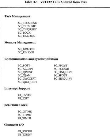
3.2.4 VRTX32 Calls Allowed from ISRs . . . . . . . . . . . . . . . . .
3-5
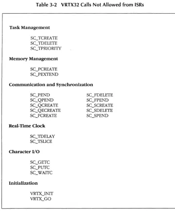
3.2.5 VRTX32 Calls Not Allowed from ISRs . . .
3-7
3.2.6 Interrupt Stack Switching . . .
3-7
3.2.7 M68000 Interrupt Levels and VRTX32 . . .
3-9
3.2.8 Interrupt Support Calls . . . . . . . . . . . . . . . . . . . . . . .. 3-10
3.3 Integrated Support for Special Devices ... . . . . . . . . . . .. 3-11
3.3.1 Real-Time Clock Support . . . 3-11
3.3.2 Real-Time Clock Calls. . . . . . . . . . . . . . . . . . . . .. 3-13
3.3.3 Character I/O Support . . . 3-14
3.3.4 Character I/O Support Calls . . . 3-15
Chapter 4 Configuration and Initialization
Table of Contents
4.4.2 VRTX32 Initialization . . . 4-12
4.4.3 Use of System Calls During Initialization ... . . . . . . . . . . .. 4-13
4.4.4 Initialization Calls . . . . . . . . . . . . . . . . . . . .. 4-15
Chapter 5 Support for User-Defined Extensions
5.1 Introduction...
5-1
5.2 User-Defined System Call Handlers. . . . . . . . . . . . .
5-2
5.2.1 Writing a System Call Handler. . . . . . . . . . .
5-3
5.2.2
AnExample System Call Handler . . .
5-4
5.3 VRTX32 Extensions . . .
5-6
5.3.1 TCREATE Routine. . . . . . . . . . . . . . . . . . . .
5-7
5.3.2 TDELETE Routine. . . . . . . . . . . . . . . . . . . . .. 5-12
5.3.3 TSWITCH Routine . . . 5-13
Chapter 6 Interfacing Software Components
6.1 Introduction...
6-1
6.2 Component Calling Conventions. . . . . . . . . . . . . . .
6-1
6.2.1 Component Call Format . . .
6-1
6.2.2 Component Call Trap Vector. . . . . . . . . . . . . . . . . . .
6-2
6.2.3 Parameter Passing . . .
6-2
6.3 Component Vectoring . . .
6-6
6.4 Component Internals . . . . . . . . . . . . . . . . . . . . . .
6-7
6.4.1 Opcode Handling . . . . . . . . . . . . . . . . . . .
6-8
6.4.2 Register Contents . . . . . . . . . . . . . . . . . . .
6-9
6.4.3 Stack Structure . . . . . . . . . . . . . . . . . . . . . . . . .. 6-10
6.4.4 Multitasking Considerations . . . 6-10
Chapter 7 System Call Reference
Table of Contents
Table of Contents
7.37 SC_TRESUME -
Resume Task . . . 7-56
7.38 SC_TSLICE -
Enable Round-Robin Scheduling. . . . . . . . . . . . .. 7-57
7.39 SC_TSUSPEND -
Suspend Task . . . "
7-59
7.40 SC_UNLOCK -
Enable Task Rescheduling. . . . . . . . . . . . .. 7-61
7.41 SC_ WAITC -
Wait for Special Character. . . . . . . . . . . . . . . . . .. 7-62
7.42 UI_ENTER -
Enter Interrupt Handler. . . . . . . . . . . . . . .. 7-63
7.43 UCEXIT -
Exit Interrupt Handler . . . 7-65
7.44 UCRXCHR -
Received-Character Interrupt. . . . . . . . . . . . . . . .. 7-66
7.45 UCTIMER -
Announce Timer Interrupt. . . . . . . . . . . . . . . . . .. 7-68
7.46 UCTXRDY -
Transmit-Ready Interrupt . . . 7-69
7.47 VRTX_GO -
Start Application Execution . . . 7-70
7.48 VRTX_INIT -
Initialize VRTX32 . . . . . . . . . . . . . . . . . . . . .. 7-71
Appendix A System Call Summary
Appendix B Return Codes
Appendix C EVT and TCB Formats
C.l Introduction . . .
C-lC. 2 Exception Vector Table . . . . . . . . . . . . . . . . . . . . . . . . . ..
C-lC.3 Task Control Block Format . . .
C-2Appendix 0 An Example
Table of Contents
Appendix E The Rescheduling Procedure
Index
list of Illustrations
Figure 1-1 VRTX32 Configuration. . . . . . . . . . . . . . . . . . . .
1-4
Figure 1-2 VRTX32 Architecture . . . . . . . . . . . . . . . . . . . . . .
1-5
Figure 2-1 Basic Architecture .... . . . . . . . . . . . . . . . . . . . . .
2-1
Figure 2-2 VRTX32 TRAP Vector . . .
2-2
Figure 2-3 Task State Transitions . . .
2-9
Figure 2-4 Memory Organization . . . 2-14
Figure 2-5 VRTX32 Workspace. . . . . . . . . . . . . . . . . . . . . . . . . . . . .. 2-18
Figure 2-6 User Memory Managed by VRTX32 . . . 2-19
Figure 3-1 Interrupt Architecture . . .
3-2
Figure 4-1 VRTX32/68000 Configuration Table . . .
4-3
Figure 4-2 EVT Reset Format . . . 4-11
Figure 5-1 Extensions Architecture . . . . . . . . . . . . . . . . . . . . . . .
5-2
Figure 5-2 Environment on Entry to TCREATE Routine . . .
5-9
Figure 5-3 User-Defined Stacks . . . 5-10
Figure 5-4 Environment on Entry to TDELETE Routine . . . 5-12
Figure 5-5 Environment on Entry to TSWITCH Routine . . . ,
5-14
Figure 5-6 Complete VRTX32 System .. . . . . . . . . . . . . . . . . . . . . . .. 5-15
Figure 6-1 Component Vector Table. . . . . . . . . . . . . . . . . . . . . .
6-6
Figure 6-2 Opcode Vector Table . . .
6-9
Figure 6-3 M68000 Stack Format . . . . . . . . . . . . . . . . . . . . . . . . . .. 6-11
Figure
C-lException Vector Table. . . . . . . . . . . . . . . . . . . . . . . .
C-2Figure
C-2Task Control Block . . . . . . . . . . . . . . . . . . . . . . . . . .
C-3Table of Contents
List of Tables
Table of Contents
List of Examples
How to Use This Manual
HUNTER
~READY
A Division of Ready Systems
Purpose of This Manual
This manual describes VRTX32, the high-performance Versatile Real-Time Executive. VRTX32 is a silicon software component that provides real-time, multitasking operating system functions for embedded microprocessor applications.
VRTX32/68000 is the implementation of VRTX32 designed for the Motorola MC68000, MC68008, and Mc68010 microprocessors.
Intended Audience
This manual is for the application programmer who requires VRTX32's real-time executive functions to build a product. The programmer should be familiar with standard real-time operating system functions and the Motorola M68000 architecture.
How This Manual is Organized
The rest of this manual is organized as follows.
• Chapter 1 is an overview of the VRTX32 software component and its M68000 microprocessor family support.
• Chapters 2 through 4 describe the basic VRTX32 services.
• Chapters 5 through 6 describe integrating VRTX32 with user-supplied code and other components.
• Chapter 7 provides an alphabetical reference to the VRTX32 system calls desCribing each call's operation, input and output values, possible return codes, and possible environments.
HllW to Use This Manual
Where to Start
This manual serves as an introduction and as a reference guide.
For an introduction to VRTX32/68000, read Chapter 1, Overview. Then read Chapters 2 through 4 for information about VRTX32's system calls.
Read Chapter 5, Support for User-Defined Extensions, and Chapter 6, Interfacing Software Components, for information about user-defined system call handlers, VRTX32 extensions, and integrating other components into a VRTX32 system.
To use this manual as a reference guide, look up any given VRTX32 system call in Chapter 7, System Call Reference. When you need additional information, refer to the earlier chapters.
Conventions
There are several conventions you should be aware of as you read the
VRTX32168000 User's Guide.
• Numbers preceded by the dollar sign ($) character are hexadecimal numbers; otherwise, numbers are decimal numbers.
• A notation such as D1[7:0] stands for register D1, bits 7 through 0; bit 0 is the least significant bit.
• In figures that show memory, low memory is at the top of the figure.
• In some figures, there are fields labeled "Reserved, must = 0". These fields
must be zero.
• All code in this manual is in Motorola assembler format.
Related Documents
We recommend the following documents for additional information.
• Getting Started With Silicon Software Components provides details on the
real-time software development process.
• How to Write a Board Support Package for VRTX describes the process of
How to Use This Manual
• Motorola's M68000 16/32-bit Microprocessor Programmer's Reference Manual
provides specific Motorola M68000 references.
• For a discussion of using VRTX32/68000 with the C language, consult Ready Systems' VRTX32 C User's Guide.
• Inteifacing a Language to Silicon Software Components provides guidelines for
writing an interface that allows a high-level language to make system calls to Ready Systems' software components.
Questions/Suggestions
If you have questions about VRTX32/68000 that are not answered by this manual, contact the Ready Systems Service and Support Group. To give us suggestions about this manual, use the reader comment card at the back of the manual. If the card is missing, send the suggestions to Ready Systems Technical Publications. Contact us at this address:
Ready Systems 449 Sherman Avenue
P.O. Box 61029 Palo Alto, CA 94306-9991
415/326-2950 TELEX: 711510608 (domestic)
Chapter 1
Overview
1.1 Introduction
HUNTER
~READY
A Division of Ready Systems
VRTX32, the high-performance Versatile Real-Time Executive, is a silicon software component for embedded microprocessors. VRTX32 is designed to take advantage of the power and features typically available on 32-bit microprocessors.
VRTX32/68000 is the implementation of VRTX32 designed for the Motorola MC68000, MC68008, and MC68010 microprocessors.
The following sections define terms basic to an understanding of VRTX32. These terms include silicon software components, embedded applications, and real-time executive. This chapter also gives an overview of VRTX32's features, configuration, and architecture.
1.1.1 Silicon Software Components
A silicon software component is an executable version of a microprocessor program that operates on all board-level microcomputers using the same type of microprocessor. Because a silicon software component does not have to be modified to make it work with custom board designs, it can be delivered in Read-Only
Memory (ROM). In fact, a silicon software component is more like a hardware component than a traditional piece of software.
The critical concept introduced by silicon software components is the use of software as a building block to connect other pieces of software in a variety of designs, without modification.
1.1.2 Embedded Applications
An embedded microprocessor is buried inside a larger system, such as an intelligent terminal, a communications system, an analytical instrument, an industrial robot, or a peripheral controller. Embedded microprocessors are to be distinguished from stand-alone microcomputers, such as small business systems or word
Overview
The software that runs on embedded microprocessors must meet a different set of requirements than software that runs on stand-alone systems. The most important requirement for embedded software systems is real-time responsiveness. The system must respond to unexpected events in the outside world rapidly enough to control ongoing processes. Another key requirement is multitasking. Multitasking is the ability of the software to handle many tasks concurrently, because events in the real world usually overlap rather than occur in strict sequence.
1 .1.3 Real-Time Executive
A common set of mechanisms is necessary to support real-time systems. These mechanisms include such things as multitasking support, CPU scheduling, communication, and memory allocation. Programmers and designers of real-time systems frequently spend more time on these basic mechanisms than on the application program itself. In embedded applications, this set of mechanisms is called a real-time operating system or a real-time executive. Programmers build the application using the time executive as the foundation. VRTX32 is a real-time executive.
1.2 VRTX32 Features
There are three categories of VRTX32 features: real-time executive features, silicon software component features, and M68000 support.
1.2.1 Real. Time Executive Features
VRTX32 provides all the features required in a real-time executive:
• Multitasking support
• Event-driven, priority-based scheduling
• Intertask communication and synchronization
• Dynamic memory allocation
• Real-time clock control, with optional time-slicing
• Character I/O support
Overview
With these features, VRTX32 provides a strong foundation for real-time, multitasking applications. VRTX32 frees designers and programmers from the problems of synchronizing multiple real-time tasks and allows them to focus their efforts on the application.
1.2.2 Silicon Software Component Features
VRTX32 provides these advantages:
• Development environment independence. VRTX32 consists entirely of an
indivisible ROM component; its configuration is not dependent on any assemblers, linkers, loaders, or host environments.
• Target environment independence. VRTX32 requires only a CPU with a
small amount of memory. This allows VRTX32 to provide true chip-level support for the M6sooo family in a wide variety of embedded applications.
• Extensibility. You can easily integrate application-specific system-level
software with VRTX32. This extended software can include user-defined system call handlers and user-supplied routines.
• Position independence. VRTX32 is written entirely in position-independent
code. This means it can be positioned anywhere in the address space of the processor.
You can easily integrate additional silicon software components into the system. Other Hunter & Ready components include TRACER, a debugger; lOX, an
input/output executive; and FMXs, file management executives. You can also supply your own component5.
1.2.3 M68000 Support
Overview
1.3 VRTX32 Configuration
The M68000 architecture uses a data structure called the Exception Vector Table (EVI) to define the addresses of user-supplied interrupt and trap service routines. There are two EVf entries that link VRTX32 to its board environment. The first of these is a vector that points to the VRTX32 entry pOint, which is the starting address of VRTX32. A second EVf entry is a vector that points to the base of the VRTX32 Configuration Table.
The user-supplied VRTX32 Configuration Table and simple, device-specific interrupt handlers provide the interface between VRTX32 and its environment. With this configuration table, you specify all the parameters required by VRTX32 for a particular system environment.
Values in the configuration table specify the beginning and extent of system-managed memory, multitasking parameters, interrupt support, and linkage to other silicon software components. This table also describes the location of any user-supplied routines invoked by significant events such as task switching. See Figure 1-1, VRTX32 Configuration.
EVT
Configuration Table
VRTX32
Overview
1.4 VRTX32 Architecture
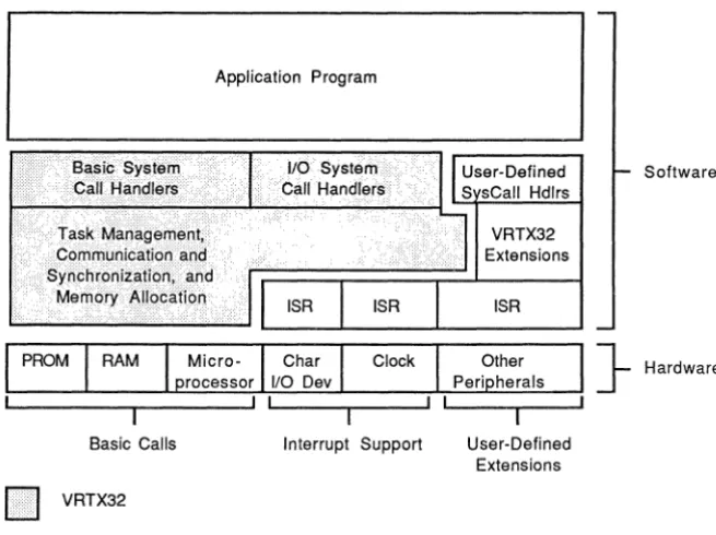
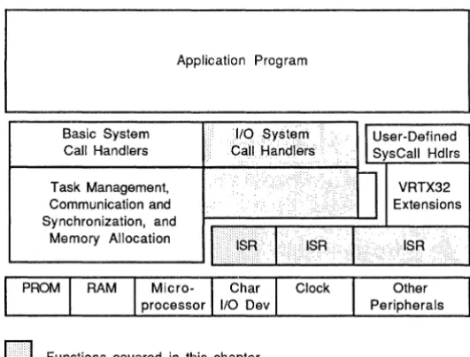
A system based on VRTX32 is layered according to function, with each level making use of the functions provided by the level below. See Figure 1-2, VRTX32
Architecture. The system hardware occupies the lowest level. The next level contains the Simplest, most hardware-dependent operating system functions. On top are user-defined application programs.
In more technical terminology, each level defines a virtual machine for the level above it. At higher levels, the functions provided by a software level are not distinguishable from those provided by the hardware. Each software level adds several instructions to the processor's instruction set. For application programs, VRTX32 adds high-level instructions (system calls) to the architecture of the M68000 microprocessor.
Basic Calis
II
VRTX32Application Program
[image:19.505.110.438.239.484.2]Interrupt Support User-Defined Extensions
Figure 1-2 VRTX32 Architecture
Software
} Hardware
Overview
are interrupt service routines (ISRs), small hardware-dependent code segments that provide interrupt handling for particular peripherals. These are not supplied with VRTX32, but Hunter & Ready offers supplementary packages that contain the ISRs for several widely used peripheral devices such as counter-timers and serial I/O chips. Consult How to Write a Board Support Package for VRTX for more information.
Other operating system mechanisms that VRTX32 does not provide are shown to the right of VRTX32 in Figure 1-2. These include user-defined system call handlers and VRTX32 extensions. These mechanisms can, for example, initialize and save the state of special devices, such as a Fourier transform chip in a signal-processing application. Like ISRs, these pieces are connected to VRTX32 with software hooks to form a unified operating system. Some hooks are defined by entries in the
configuration table. Refer to Chapter 4, Configuration and Initialization, and Chapter 5, Support for User-Defined Extensions.
Chapter 2
Basic System Calls
2.1
IntroductionHUNTER
~READY
A Division of Ready Systems
This chapter describes the process of making a VRTX32 system call and VRTX32's basic operations. These operations are organized into three categories:
• Multitasking management
• Memory allocation
• Intertask communication and synchronization
Figure 2-1, Basic Architecture, shows these three operations.
Application Program
110 System Call Handlers
o
Functions covered in this chapterFigure 2-1 Basic Architecture
VRTX32
Extensions
ISR
Basic System Calls
2.1.1 Accessing VRTX32
The M68000 architecture uses a data structure known as the Exception Vector Table (EVT) to control access to service routines for hardware-generated interrupts and software-generated traps. Your application accesses VRTX32 as a trap service routine through this same data structure.
The EVT is usually based at physical address O. However, the Mc68010 architecture allows you to locate the EVT at any address by setting the Vector Base Register (VBR), There are 16 TRAP vectors in the EVT, numbered 0 through 15. See Figure C-1, Exception Vector Table, for the location of the TRAP vectors.
The application calls VRTX32 by issuing a TRAP instruction. The TRAP #n
instruction generates a trap exception; n is the TRAP vector number. When this trap exception occurs, the CPU loads a new Program Counter (PC) value from the EVT. For the trap to VRTX32, this new PC value contains the address of the VRTX32 entry point.
You can choose any of the 16 TRAP numbers for VRTX32 access. Figure 2-2, VRTX32 TRAP Vector, shows the format of vector 32, the vector corresponding to TRAP #0, in the case where VRTX32 resides at physical address $1000. Vector 32 is located at EVT offset $080.
EVT Offset
r---~
$80 $0000
$82 $1000
Figure 2-2 VRTX32 TRAP Vector
2.1.2 System Call Format
All VRTX32 system calls are made with the TRAP instruction. When calling VRTX32, register DO must contain a 32-bit function code that specifies the desired VRTX32 system call. When a call completes, VRTX32 returns a 32-bit return code in register DO. When the call is successful, VRTX32 returns a value of zero; otherwise VRTX32 returns an error code (refer to Appendix B, Return Codes).
Basic System Calls
passed in address register AO. Unless otherwise indicated, VRTX32 system calls leave all input registers except DO intact. Refer to Appendix A, System Call Summary, which lists all VRTX32 calls with their input parameters and output results.
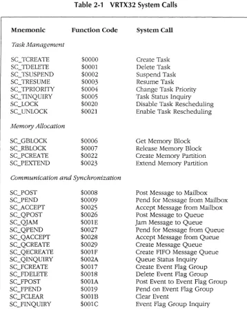
Table 2-1, VRTX32 System Calls, lists all VRTX32 system calls and their function codes.
2.2 Tasks
Real-time systems are designed to perform seemingly unrelated functions in a nonsequential way, using the processor and I/O devices as effiCiently as possible. Several common processing situations lend themselves to this control philosophy. Examples include listening for input from several devices at the same time, reading or writing a block of data while concurrently performing arithmetic computations, and implementing communications applications.
VRTX32 supports real-time systems with a set of basic multitasking mechanisms. The basic unit controlled by VRTX32 is the task, a logically complete path of user
code. The task is a collection of actions that deals with one issue asynchronously and in real time. Several tasks can operate autonomously from the same piece of code, or tasks can be located in separate code modules. In a multitasking system, several tasks appear to execute Simultaneously, although VRTX32 actually allocates CPU control among tasks in an interleaved fashion.
Tasks are active or inactive. Inactive tasks are dormant tasks, while active tasks have executing, suspended, and ready task states. There can be as many active
tasks as the application requires. All active tasks have priority levels, and 255 of the
active tasks can have unique identification numbers. VRTX32 moves tasks from one task state to another based on the task priority level and as the result of system calls.
The task's Task Control Block (TCB) and the task stack maintain task status ifl.iormation for each active task not in control of the CPU.
Basic System Calls Mnemonic Task Management SC3CREATE SCTDELETE SCTSUSPEND SCTRESUME SCTPRIORITY SCTINQUIRY SCLOCK SCUNLOCK Memory Allocation SCGBLOCK SC_RBLOCK SC_PCREATE SCPEXTEND
Table 2-1 VRTX32 System Calls
Function Code $0000 $0001 $0002 $0003 $0004 $0005 $0020 $0021 $0006 $0007 $0022 $0023 System Call Create Task Delete Task Suspend Task Resume Task Change Task Priority Task Status Inquiry Disable Task Rescheduling Enable Task Rescheduling
Get Memory Block Release Memory Block Create Memory Partition Extend Memory Partition
Communication and Synchronization
SC_POST SCPEND SC_ACCEPT SC_QPOST SC_QJAM SC_QPEND SC_QACCEPT SCQCREATE SC_QECREATE SCQINQUIRY SC]CREATE SC]DELETE SC]POST SC]PEND SCFCLEAR SC]INQUIRY $0008 $0009 $0025 $0026 $OOlE $0027 $0028 $0029 $OO1F $002A $0017 $0018 $OOlA $0019 $OOlB $OO1C
Post Message to Mailbox Pend for Message from Mailbox Accept Message from Mailbox Post Message to Queue Jam Message to Queue
Pend for Message from Queue Accept Message from Queue Create Message Queue Create FIFO Message Queue Queue Status Inquiry Create Event Flag Group Delete Event Flag Group Post Event to Event Flag Group Pend on Event Flag Group Clear Event
Event Flag Group Inquiry
[image:24.508.93.452.59.513.2]Basic System Calls
Table 2-1, continued
Mnemonic Function Code System Call
Communication and Synchronization, continued
SCSCREATE SCSDELETE SCSPOST SCSPEND SC_SINQUIRY Interrupt Support UI_ENTER UCEXIT Real-Time Clock SC_GTIME SC_STIME SCTDELAY SC_TSLICE UCTIMER Character I/O SCGETC SC]UTC SC_WAITC UCRXCHR UCTXRDY Initialization $002B $002C $002E $002D $002F $0016 $0011 $OOOA $OOOB $OOOC $0015 $0012 $OOOD $OOOE $OOOF $0013 $0014 $0030 $0031 Create Semaphore Delete Semaphore Post Unit to Semaphore Pend on Semaphore Semaphore Inquiry
Enter Interrupt Handler Exit Interrupt Handler
Get Time Set Time Delay Task
Enable Round-Robin Scheduling Announce Timer Interrupt
Get Character Put Character
Wait for Special Character Received-Character Interrupt Transmit-Ready Interrupt
Initialize VRTX32
Basic System Calls
The rest of this section talks about these concepts in more detail and discusses VRTX32's multitasking management calls.
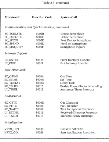
2.2.1 Task States and State Transitions
In a multitasking environment, tasks exist in and are moved between one of four states: executing, ready for execution, suspended, or dormant.
This section discusses the VRTX32 system calls that affect a task's state. Refer to the following sections and chapters for detailed explanations of these calls.
Executing Task State. An executing task has control of the CPU and is executing its
instruction path. Only one task executes at a time.
Suspended Task State. A suspended task is suspended in mid-execution, and is
waiting to be readied by a system call or an event.
A task can suspend for any of these reasons:
• A task suspend call, SC_TSUSPEND, specifies that task either by priority or by ID number. A task can suspend itself.
• The task issues an SC_ TDELA Y call and suspends for a specified time interval.
• The task issues an SC_PEND or SC_QPEND call, but no message from a task or an interrupt handler is waiting at the mailbox or queue.
• The task issues an SC_FPEND call, but the correct event flag(s) are not set.
• The task issues an SC_SPEND call, but the resource's semaphore has a zero value (the resource is not available).
• The task issues an SC_ WAITC call and waits for an I/O device to send a special character.
• The task issues an SC_GETC call, but the input buffer maintained by VRTX32 is empty. The task waits for a character to be put into the buffer.
• The task issues an SC]UTC call, but the output buffer is full. The task waits for a character to be removed from the buffer.
Basic System Calls
It is important to note that suspensions are independent and additive. For example, when a task is suspended while waiting for a message and it is also explicitly suspended by another task, both suspending conditions must be removed before the task is ready for execution.
A final point about the suspended task state is that when a task suspends, VRTX32 notes the current interrupt level. When this task is resumed, interrupts are enabled to the level they were enabled when the task was suspended.
Ready Task State. A ready task is one that is ready for execution; for example, a
task that has just been created is ready for execution. However, a ready task cannot gain control of the CPU until all higher-priority tasks in the ready or executing state either complete, suspend, or become dormant.
A task can move from the suspended state to the ready state for any of these reasons:
• An SC_TRESUME call readies a task suspended by an SC_TSUSPEND call.
• A time delay expires, which can ready a task suspended by an SC_TDELAY call, or a task that timed out pending for a message.
• An SC_POST or SC_QPOST call posts a message to a task that is waiting on a mailbox or queue.
• An SC_FPOST call posts an event(s) to an event flag group and a task was waiting for that event(s).
• An SC_SPOST call indicates that the resource is available and a task was waiting on that resource's semaphore.
• An interrupt service routine (ISR) sends a special character (with the UCRXCHR call) to VRTX32. VRTX32 then transfers the character to a task suspended by an SC_ WAITC call.
• An ISR sends a character to the input buffer Witll the UI_RXCHR call. The tasks suspended on an empty buffer are readied in the order they were suspended, one at a time, with each succeeding UCRXCHR call.
• An ISR retrieves a character from the output buffer with the UC TXRDY call. The tasks suspended on a full buffer are readied in the order they were suspended, one at a time, with each succeeding UC TXRDY call.
8asic System Calls
Because the task that loses control is not suspended, no bits are set in the TBSTAT field of its TCB. The task remains in the ready state until all higher-priority tasks complete, suspend, or become dormant, at which point the task moves back to the executing state.
For example, when a task is executing and a higher-priority task's SC_TDELAY interval expires, the higher-priority task gains control. This moves the lower-priority task from the executing state to the ready state.
This transfer of control from one task to another is called a task switch. Refer to
Section 2.2.2, Task Scheduling, for more information about task switching, and Appendix E, The Rescheduling Procedure, for information about the process that leads to task switches.
Dormant Task State. A dormant task is a task that is not initialized, or a task whose
execution is terminated Ctask deleted). No TCB is assigned to it.
Tasks are in the dormant state before they are created; they reenter the dormant state when they are deleted with an SC_TDELETE call. When all user tasks are deleted or suspended, the system switches to the idle task until an external event occurs.
Figure 2-3, Task State Transitions, shows these task states.
2.2.2 Task Scheduling
VRTX32 schedules and manipulates tasks based on each task's identification number and priority.
Each task has a unique identification (ID) number that allows it to be selectively
readied, suspended, or deleted. You specify the task ID number when you create the task: either a unique ID number from 1 to 255, or an ID of zero, which indicates that no ID is aSSigned. CAny number of tasks with an ID of zero can exist.)
VRTX32 schedules control of the CPU based on the highest-priority task that is ready to execute. A task's priority is determined by two things:
• the priority level you assign to the task when it is created
Any call that causes task switching
SC3CREATE
Scheduler
Real-time Event or
[image:29.507.96.449.61.354.2]SC_TRESUME
Figure 2-3 Task State Transitions
Basic System Calls
SC_TSUSPEND SC_TDELAY SC_PEND SC_QPEND SCJPEND SC_SPEND SC_WAITC SC_GETC SC._PUTC
You must specify a priority level for each task when it is created. There are 256 priority levels ranging from zero to 255; zero is the highest-priority level. Any number of active tasks can exist at each priority level.
In a group of equal-priority tasks, tasks execute in the order that they become ready (first-in/first-out (FIFO) order). In other words, the "oldest" ready task is the highest-priority task in its highest-priority group. (Refer to Section 2.2.1, Task States and State Transitions, for a discussion of ready tasks.) For example, the task that was created first executes before newer ready tasks of the same priority.
Basic System Calls
information about this procedure.) You do not execute special system calls to accomplish task switching once initialization is complete and system execution is underway.
The highest-priority task executes until the task terminates its own operation, the task suspends, or a higher-priority task is ready to execute. When one of these events occurs, the rescheduling procedure determines the next task to move from the ready state to the executing state.
The rescheduling procedure can be disabled with the SC_LOCK call, and reenabled with the SC_UNLOCK call.
The way tasks are scheduled can be altered with the change task priority (SC_TPRIORITY) call, the delay task (SC_TDELAY) call, and the enable time-slice (SC_TSLICE) call. The SC_TPRIORITY call changes the priority of a task. A task switch can occur if the new priority of the affected task is higher than that of the calling task, or if the task lowers its own priority and there is a ready task with a higher priority. The current task can also change the execution order of equal-priority ready tasks by issuing SC_TPRIORITY with the "new" equal-priority equal to the "old" priority. This makes the affected task ready after the other members of its priority group. Note that the calling task can voluntarily preempt itself using this technique if there are equal-priority tasks that are ready to execute.
The SC_TDELAY call delays the calling task's execution for a specified number of VRTX32 clock ticks. A task can also use this call to voluntarily preempt itself; if the task specifies a zero delay value, it moves to the end of its priority group. The next equal-priority ready task executes.
The SC_ TSLICE call enables optional round-robin scheduling among equal-priority tasks. At the end of a time-slice interval, or when a task in the priority group suspends, the tasks in the priority group rotate. The next ready task is given a chance to execute.
2.2.3 Task Control Block (TCB)
Basic System Calls
This information is stored in the task's Task Control Block (TCB) and on the task's stack. The TCB is a data structure in the VRTX32 Workspace. Each active task has a TCB, but no TCB is defined for a dormant task. See Figure C-2, Task Control Block, for a diagram of the TCB.
A task's TCB is frozen while the task is executing and is not altered until the task moves to the ready, suspended, or dormant state. When the task moves to the ready or suspended state, the TCB saves the contents of registers DO through D5, AO through A3, SSP and USP, as well as other status information about the task. The task's stack saves registers D6, D7, A4 through A6, PC, and the Status Register (SR),
When the task moves to the suspended state, the TBSTAT field in the TCB indicates the reason for suspension. When the task moves to the dormant state, its TCB is no longer associated with that task.
2.2.4 Task Management Support
VRTX32 manages tasks with these calls:
SC_TCREATE SC_TDELETE SC_TSUSPEND SC_TRESUME SC_TPRIORITY SCTINQUIRY SC_LOCK SC_UNLOCK
Task Create Task Delete Task Suspend Task Resume Task Priority Change Task Status Inquiry Disable Task Rescheduling Enable Task Rescheduling
The SC_ TCREA TE call creates a task with a priority level, an ID number, a mode (Supervisor or User), and a specified start address. The task begins execution with interrupts enabled (interrupt level 0). The creator task's environment determines the new task's TCB and stack values.
It is possible to create a task with an ID of zero. However, it is a special case because other tasks cannot reference it. The SC_TDELETE, SC_TSUSPEND,
SC_TPRIORITY, and SC_TINQUIRY calls reference the calling task when a zero ID is specified.
Basic System Calls
The SC_TSUSPEND call suspends one or more tasks by priority or ID number. A task can suspend itself. When a task is suspended, a flag in the TCB's TBSTAT field is set to indicate the reason for suspension. An explicitly suspended task is not resumed until an SC_TRESUME call is issued.
The SC_TRESUME call resumes the execution of one or more tasks previously suspended by an SC_TSUSPEND call. You can specify the tasks to be resumed by priority or ID number.
A task can change the priority of another task or of itself with the SC_ TPRIORITY call. You specify the task by ID number. (You can change the priority of an explicitly suspended task, but it remains explicitly suspended until you issue an SCTRESUME call.)
The SC_TINQUIRY call obtains the task ID number, priority level, and status
information from the TCB of any task, including itself. We recommend that ISRs use this call only for general performance or statistical monitoring. When this call is made before any tasks are created, the data returned is invalid.
You can disable the rescheduling procedure with the SC_LOCK call. This can be useful when, for example, there is a critical section of code that higher-priority tasks must not preempt. The task that issues the SC_LOCK call retains processor control, even though higher-priority tasks may be ready to run. The SC_UNLOCK call reenables the rescheduling procedure. However, it cancels only the last SC_LOCK call. (The maximum lock/unlock nest count supported is 65,535.)
CAUTION
Any call that suspends the current task causes unpredictable results when task rescheduling is disabled with the SC_LOCK call.
2.2.5 Multitasking Management Calls
Basic System Calls
SC3PRIORI1Y
SCTINQUIRY
Table 2-2 Task Management Call Summary
Creates a task with a specified priority, ID number, mode, and address.
Deletes one or more tasks specified by priority or ID number.
Suspends one or more tasks specified by priority or
ID number.
Resumes one or more tasks specified by priority or ID number.
Changes the priority of a task specified by ID number.
Obtains the ID number, priority, TCB address, and status of a task specified by ID number.
Disables task rescheduling until SC_UNLOCK is issued.
SCUNLOCK Enables task rescheduling.
2.3 Memory
The M68000 microprocessor's 24-bit PC and its 24 address lines define an address space of 16 megabytes (224 bytes), although the actual amount of memory in the system is often considerably less. The memory map of a VRTX32-based system consists of these modules:
• VRTX32 code: the VRTX32 PROM set. Note that VRTX32 can be placed in
random access read/write memory, and can be loaded into memory from disk, if you wish.
• User load module: the software package you are responsible for developing,
assembling, linking, and placing in the execution environment.
• VRTX32 Workspace: contains system variables, TCBs, and stacks.
• VRTX32-managed user memory: one or more partitions, or pools, of memory
[image:33.503.91.449.50.335.2]Basic System Calls
• Optional Hunter & Ready components, such as lOX, FMX, or TRACER.
[image:34.504.121.436.152.515.2]• Optional user-supplied components.
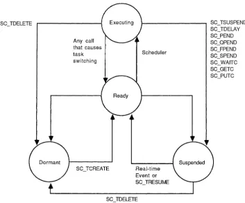
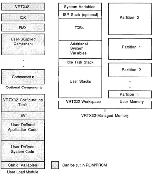
Figure 2-4, Memory Organization, is an overview of the entire memory organization of a VRTX32 system. The shading shows what can be burned into ROM; everything else must be in dynamic read/write memory.
V R T X 3 2 I System Variables
lOX ISR Stack (optional) Partition 0
FMX· TCBs
Additional
System Partition 1
Variables
Idle Task Stack
Partition 2
CorllpOnerlt(l .•
User Stacks
Optional Components
Partition n
VRTX32 Workspace User Memory
VRTX32-Managed Memory
·StatidVariables
Iii
Can be put in ROM/PROM User Load ModuleBasic System Calls
The user load module holds your application code and any user-defined, system-level code, as described in Chapters 3 through 6. In addition, the user load module contains the EVT, the configuration table, and any static variables associated with your application or with system code. Refer to Appendix D, An Example, for an example of a user load module.
The VRTX32 Workspace contains the system variables, the optional interrupt stack, the TCBs, control structures for queues, event flag groups, and semaphores, control structures for VRTX32-managed user memory, the idle task stack, and stack areas for each task in the system. VRTX32 is responsible for setting up and managing the stacks and for initializing and managing the TCBs.
The VRTX32-managed user memory consists of one or more partitions, or chunks, of memory. These partitions can be noncontiguous. Each partition is subdivided into one or more fixed-size blocks of memory that can be allocated dynamically. The rest of this section describes how VRTX32 manages user memory and its own workspace.
2.3.1 Memory Allocation
A task's demand for memory varies over the course of its execution, and different tasks usually have different requirements. The operating system treats memory as a resource and allocates that resource among competing tasks, just as it allocates control of the CPU among competing tasks.
Multitasking executives generally use one of two approaches to memory allocation:
static allocation of fixed-size memory blocks or dynamic allocation of variable-size blocks. In static allocation, each task is assigned a block of memory at system initialization. This block is dedicated to that one task and cannot be used by any other task. In dynamiC allocation of variable-size memory blocks, available memory eventually becomes fragmented and unusable as tasks allocate and release memory blocks from the available pool.
Basic System Calls
A problem with the buddy system and other variable-size memory allocation systems is that as memory grows progressively more fragmented, occasions inevitably arise when a request cannot be met. Even though there can be enough total free memory, it can be so fragmented that a large enough contiguous block cannot be found. These occasions cannot be predicted in advance and compensated for, because the order of memory requests usually cannot be anticipated in a real-time system. This design introduces an element of unpredictability into the total system behavior beyond that of the external environment. This additional unpredictability is unsatisfactory in real-time systems, because real-time systems cannot tolerate a memory system that works only some of the time.
2.3.2 Memory Allocation Support
The designers of VRTX32 felt static allocation was too restrictive, but the memory compaction resulting from dynamic allocation led to unacceptable indeterminacy and imposed too much system overhead. Thus, the VRTX32 memory allocation
mechanism is a compromise between the two schemes. The VRTX32 memory management schemes are determinate, yet they allow flexibility in the sizes of the stacks allocated to each task and in the sizes of the partitions that divide user memory.
In the VRTX32 Configuration Table, you specify the starting address and size of VRTX32 Workspace, the optional interrupt stack's size, the maximum number of tasks that can exist at anyone time, and each task's stack area size. The VRTX32
Workspace must be large enough to contain VRTX32 system variables, the optional interrupt stack, one TCB for each task, and stack areas for every task in the system. In addition, the VRTX32 Workspace must be large enough to accommodate a control block for each memory partition and extenSion, and a control block for each defined message queue. Refer to Section 4.3, Determining VRTX32 Workspace Size, for details.
When a task is created, VRTX32 automatically allocates the task's fixed-size stack (or stacks) in the VRTX32 Workspace. The stack size is specified by the User-Stack-Size and Sys-Stack-Size parameters in the configuration table. (Refer to Chapter 4, Configuration and Initialization.)
Basic System Calls
A User mode task is given two separate stacks, referenced by the User Stack Pointer
(USP) and Supervisor Stack Pointer (SSP) (the TBUSP and TBSSP fields in the task's TCB). A Supervisor mode task is given a single stack, referenced by the SSP (the TBSSP field in the task's TCB).
VRTX32 also dynamically allocates partitions of user memory. You can dynamically define partitions to match the often noncontiguous chunks of memory that make up the actual physical organization of memory. Each partition of user memory has blocks of a fixed size set when that partition is created.
VRTX32 manages its memory allocation system with these system calls:
SCGBLOCK Get Memory Block
SC_RBLOCK Release Memory Block
SC_PCREATE Create Memory Partition
SC_PEXTEND Extend Memory Partition
The SC_PCREATE call defines a contiguous area of user memory as a partition. Parameters passed with the call specify the partition start address, the partition size, the partition ID number, and the block size. There cannot be more than 32K blocks in the partition as first defined by the SC_PCREATE call. However, you can extend the partition with the SC_PEXTEND call. The block size must not equal zero and must be less than or equal to the partition size. To avoid wasted space, the partition size should be an integer multiple of the block size.
The SC_GBLOCK call acquires a block of memory from the partition. You can repeat this call until all blocks in the partition are allocated.
The SC_RBLOCK call releases a block of memory back to the partition. A task's blocks are not automatically released when the task is deleted, because blocks can be passed to other tasks for data exchange. Therefore, you should use the SC_RBLOCK call to release all blocks before you delete a task.
The SC_PEXTEND call enlarges a previously-defined partition to include an additional range of memory locations. There cannot be more than 32K blocks in an extension. However, you can issue multiple SC_PEXTEND calls to define more blocks. The extension and the original partition do not have to be contiguous with each other.
Basic System Calls
The VRTX32 partition!block system has several key features. These features give VRTX32's memory allocation system great flexibility and most of the advantages of a variable-size block system, without the indeterminacy and excessive system
overhead. First, you can define partitions in other partitions to achieve different block sizes. For example, one partition can be entirely in a single block of another partition. This means that blocks can easily be divided into sub-blocks. Second, you can define two partitions to cover the same area of memory, allowing you to allocate blocks of two different sizes from the same memory region. The only requirement here is that you must release all blocks of one size before you allocate any blocks of the other size.
Figures 2-5, VRTX32 Workspace, and 2-6, User Memory Managed by VRTX32, show how memory is subdivided.
VRTX-Workspace-Addr ~
System Variables
ISR Stack (if allocated)
TCBs
Additional system variables (dynamically allocated for VRTX-Workspace-Size
-
partition, queue, event flaggroup, and semaphore control structu res).
Idle Task Stack
User-Stack-Size
r - -
- - - -
-Sys-Stack-Size
User-Stack-Size
- - - -
-Sys-Stack-Size User-Stack-Size
- -
- -
- -
--
Sys-Stack-SizeFigure 2-5 VRTX32 Workspace
}
J-}
2624
ISR-Stack-Size
User-Task-Count X TCB size (160)
} Idle-Task-Stack-Size
User-Task-Count X (User-Stack-Size +
Sys-Stack-Size)
Basic System Calls
Partitions and Extensions Defined by SC_PCREATE and SC_PEXTEND Start address
Size
"""""""""-'-"""""""""",","""""",,,,",,,,,,",,,,,,"9}
Block sizeFigure 2-6 User Memory Managed by VRTX32
2.3.3 Memory Allocation Calls
Table 2-3 contains a summary of the system calls that allow programs to obtain and return blocks of memory from a specified partition. The summary also includes the VRTX32 calls that create and extend partitions. These calls do not initiate the rescheduling procedure, and so cannot cause a task switch. For detailed information on each of the calls, refer to Chapter 7, System Call Reference.
SCRBLOCK
SC]CREATE
SC]EXTEND
Table 2-3 Memory Allocation Call Summary
Gets a memory block from a specified partition.
Releases a memory block back to the specified partition.
Creates a memory partition of a specified size, ID number, block size, and address.
Basic System Calls
2.4 Intertask Communication and Synchronization
A real-time multitasking system has several communication and synchronization needs:
• A task must be able to exchange data with other tasks and ISRs .
• A task must be able to synchronize with other tasks and ISRs, in these ways:
• Unilateral synchronization: a task synchronizes with another task or an ISR.
• Bilateral synchronization: two tasks synchronize with each other.
• Conjunctive synchronization: a task synchronizes with several events.
• Disjunctive synchronization: a task synchronizes with the first of several possible events .
• Tasks must occasionally be able to mutually exclude each other so that each is guaranteed exclusive control of a protected resource.
VRTX32 provides several mechanisms to meet these needs. Tasks and ISRs can pass long-word C32-bit) messages using mailboxes and queues to meet all the above needs. Messages can be significant in themselves, or pointers to larger messages. Tasks and ISRs can also use event flags for synchronization, and semaphores for mutual exclusion.
2.4.1 Mailboxes
A mailbox is a user-defined long-word variable in user read/write memory. Mailboxes allow tasks to pass long-word C32-bit) nonzero messages. VRTX32 does not create mailboxes; instead, you set up the memory for the mailbox. The application should initialize the mailbox to the appropriate value: zero when the mailbox is immediately available; nonzero when the mailbox is used for mutual exclusion.
These are VRTX32's mailbox system calls:
SC_POST SCPEND SCACCEPT
Basic System Calls
A task or an ISR sends a message to a specified mailbox with the SC_POST call. If a message is already in the mailbox (mailbox value is nonzero), VRTX32 returns an error code.
To receive the message, another task issues an SC_PEND call. If there is a message in the mailbox (mailbox value is nonzero), the task receives the message and continues execution. VRTX32 resets the mailbox to zero when the message is received.
If there is no message in the mailbox (mailbox value is zero), the task attempting to receive a message with SC_PEND suspends until the message arrives. You can specify a nonzero timeout value that allows the task to resume execution if no message arrives during that time period.
When the task attempts to receive the message with an SC_ACCEPT call and no message is present, the task does not suspend. Instead, VRTX32 returns an error code and the task continues execution. To avoid suspension, ISRs must use SC_ACCEPT rather than SC_PEND to receive messages.
When a task pending at a mailbox is suspended with the SC_ TSUSPEND call, it can receive a message. However, the task remains suspended until it is resumed with the SC3RESUME call.
More than one task can wait at the same mailbox if each task issues an SC_PEND call with the same mailbox address. When a message is sent to that mailbox, the highest-priority task receives the message and is placed in the ready state. (Tasks receive messages according to their priority level at the time they pend on the mailbox. Changing a pended task's priority does not affect the order in which messages are allocated.)
You can use VRTX32's mailbox calls for data transfer, synchronization, and mutual exclusion. To synchronize two tasks with each other, Task A posts a message to one mailbox, then immediately pends at another mailbox. Task B simply does the reverse: it receives Task A's message, then immediately posts a message to enable Task A.
Basic System Calls
2.4.2 Queues
Message queues are fixed-length buffers that you create dynamically. Queues are
not part of your set of variables; they are VRTX32-managed structures referenced by a queue ID number.
Queues allow tasks to pass long-word (32-bit) messages. (A queue of length 1 behaves logically like a mailbox.)
These are VRTX32's queue system calls: SC_QCREATE
SC_QECREATE SC_QPOST SC_QJAM SC_QPEND SC_QACCEPT SC_QINQUIRY
Create Message Queue Create FIFO Message Queue Post Message to Queue Jam Message to Queue Pend for Message from Queue Accept Message from Queue Queue Status Inquiry
You create a queue in VRTX32's Workspace with the SC_QCREATE or SC_QECREATE call, specifying the queue ID number and the queue size. Tasks pend on a queue created with SC_QCREATE in priority order. With the SC_QECREATE call, you specify whether they pend in priority or FIFO order.
Tasks and ISRs send messages to queues with the SC_QPOST and SC_QJAM calls. The SC_QPOST call puts the messages at the end of the queue; messages are handled in flrst-in/flrst-out (FIFO) order. If the queue is full, an error code is returned.
SC_QJAM puts the message at the beginning of the queue. When a queue is created with SC_QCREATE or SC_QECREATE, VRTX32 adds one queue entry to the number you specify. This additional entry is reserved at the beginning of the queue for a message posted with the SC_ QJAM call when the queue is otherwise full. If the queue is full and a message has already been "jammed", an error code is returned. As an alternative to mixing SC_QJAMs and SC_QPOSTs, you can use the SC_QJAM call to post all messages to the queue. In this case, you can use the full size of the queue (including the reserved entry), and messages are handled in last-in/first-out (LIFO) order.
Basic System Calls
message arrives during that time period. If a task attempts to receive a message from an empty queue with SC_QACCEPT, it is not suspended. Instead, VRTX32 returns an
error code and the task continues execution. To avoid suspension, ISRs must use
SCQACCEPT.
When two or more tasks pend at an empty priority-order queue, the task with the
highest priority receives the first message sent to the queue. (Tasks receive messages
according to their priority level at the time they pend on the queue. Changing a
pended task's priority does not affect the order in which messages are allocated.) When two or more tasks pend at an empty FIFO-order queue, the task that pended first receives the first message sent to the queue.
The SC_QINQUIRY call obtains information about a queue. This call returns the number of messages in the queue and the message at the head of the queue. This message is returned to the caller but is not removed from the queue.
You can use queues for mutual exclusion of several resources of the same type. Assign each type of resource, such as a line printer, a spedfic queue. The length of this queue should be equal to the number of resources in that resource type, such as the number of line printers on the system. This length determines how many tasks can use the resource type at the same time.
For example, suppose there are five line printers in the system. A priority-order line printer queue of length five locks these printers. This line printer queue is initialized with printer ID numbers. All tasks attempting to use a line printer pend at the line printer queue. When a printer becomes available, the highest-priority pended task receives that printer's ID number and uses the printer. When the task finishes with the line printer, it posts the printer ID number back to the line printer queue. This enables another task to use that printer.
2.4.3 Event Flags
An event flag group is a global, long-word (32-biO structure in VRTX32 Workspace.
Each of the 32 bits in the event flag group is an event flag. Event flags have two states: set (one) and cleared (zero). When a flag is set, the assodated event has occurred. This means that tasks and ISRs can use event flags to signal the occurrence of events to other tasks.
Basic System Calls
• A task can wait for a disjunctive (OR) set of events to occur. In other words, a task specifies a set of events to wait for. When the first one occurs, the task is readied.
• A task can wait for a conjunctive (AND) set of events to occur. This means that a task specifies a set of events to wait for, and is not readied until all the events have occurred.
• Many tasks can be waiting for the same event. This means that a task or an ISR "broadcasts" the event to all the tasks waiting for it to occur.
These are VRTX32's event flag system calls:
SC]CREATE Create Event Flag Group
SC]DELETE Delete Event Flag Group
SC_FPEND Pend on Event Flag Group
SC_FPOST Post Event to Event Flag Group
SC]CLEAR Clear Event
SC]INQUIRY Event Flag Group Inquiry
The SC_FCREATE call creates a 32-bit event flag group in VRTX32 Workspace, and returns the event flag group ID number. Each event flag group and semaphore is associated with a control block. You specify the maximum number of control blocks in the VRTX32 Configuration Table (refer to Section 4.2, VRTX32
Configuration Table). If you try to create more event flag groups and/or semaphores than you've specified in the configuration table, VRTX32 returns an error code.
The SC_FDELETE call deletes an event flag group, making its control block available for reuse. There may be tasks pending on the event flag group; you can specify whether to delete only if there are no tasks pending, or to force a delete. In the latter case, all pending tasks are readied.
Tasks wait for one or more events with the SC_FPEND call. The task specifies whether it is an AND pend or an OR pend. If the specified event flags are set, the task continues execution (the SC_FPEND call does not clear the event flags). If the specified event flags are not set, the task suspends. You can specify a nonzero timeout value that allows the task to resume execution if the event does not occur during that time period. If the task is suspended on an event flag group and the group is deleted, the task is readied and VRTX32 returns an error code.
Basic System Calls
Tasks and ISRs signal one or more events with the SC_FPOST call. Tasks suspended on the event flag group are readied if the SC]POST call satisfies their AND or OR pend. If an event flag is already set (one), and SC]POST tries to set it again, VRTX32 returns an error code. However, if SC_FPOST specifies several event flags, and some of them are already set, VR1X32 returns an error code and sets any event flags that were not previously set.
The SC_FCLEAR call clears event flags. An event flag should be cleared before an attempt is made to post to it again.
A task or an ISR can check the status of event flags by issuing the SC_FINQUIRY call. The entire 32-bit event flag group is returned to the caller.
2.4.4 Semaphores
VRTX32 provides counting semaphores for mutual exclusion. A counting
semaphore is a word (16-bit) variable in VRTX32 Workspace that has an initial value from 0 to 65,535. An initial value of zero indicates that the resource starts in a locked state. A nonzero value indicates how many tasks can access the resource at one time.
These are VR1X32's semaphore system calls:
SCSCREATE SC_SDELETE SC_SPEND SCSPOST SC_SINQUIRY
Create Semaphore Delete Semaphore Pend on Semaphore Post Unit to Semaphore Semaphore Inquiry
The SC_SCREATE call creates a semaphore in VRTX32 Workspace, and returns the semaphore ID number. You specify the initial value of the semaphore and whether tasks pend on the semaphore in priority order or FIFO order.
Each semaphore and event flag group is associated with a control block. You
specify the maximum number of control blocks in the VR1X32 Configuration Table (refer to Section 4.2, VRTX32 Configuration Table). If you try to create more
semaphores and/or event flag groups than you've specified in the configuration table, VRTX32 returns an error code.
Basic System Calls
To wait for the restricted resource, a task issues the SC_SPEND call. If the semaphore has a nonzero value, the semaphore is decremented and the task
continues execution. If the semaphore is zero, the task suspends. You can specify a nonzero timeout value that allows the task to resume execution if the resource does not become available during that time period. If the task is suspended on the semaphore and the semaphore is deleted, the task is readied and VRTX32 returns an error code.
A task or an ISR signals that the resource is available with the SC_SPOST call. This call increments the semaphore; however, if a task is waiting, it is readied immediately and the semaphore is not incremented. If a semaphore receives an SC_SPOST when its value is already at the maximum of 65,535, an overflow occurs and VRTX32 returns an error code.
When two or more tasks pend at a priority-order semaphore, the task with the highest priority is readied with the next SC_SPOST call. (Tasks are readied according to their priority level at the time they pend on the semaphore. Changing a pended task's priority does not affect the order in which tasks are readied.) When two or more tasks pend at a FIFO-order semaphore, the task that pended first is readied with the next SC_SPOST call.
Tasks and ISRs can check the value of a semaphore with the SC_SINQUIRY call.
2.4.5 Communication and Synchronization Calls
Basic System Calls
Table 2-4 Communication and Synchronization Call Summary
SC]OST
SC]END
SC_QCREATE
SC]DELETE
Posts a message to a specified mailbox.
Pends for a message from a specified mailbox. You can specify an optional time limit.
Accepts a message from a specified mailbox, but does not suspend the caller if no message is present.
Posts a message to a queue specified by ID number.
Jams a message to the beginning of a queue specified by ID number.
Pends for a message from a queue specified by ID number. You can specify an optional time limit.
Accepts a message from a queue specified by ID number, but does not suspend the caIler if no message is present.
Creates a queue with a specified ID number and a specified number of queue entries.
Creates a queue with a specified ID number and a specified number of queue entries. You specify whether tasks pend in priority or FIFO order.
Obtains the number of messages and the contents of the first message in a specified queue. The message is not extracted from the queue.
Creates an event flag group and returns the event flag group ID number to the caller.
Deletes an event flag group specified by ID number. You can specify to delete only if there are no tasks pending on the event flag group, or to force a delete and ready all pending tasks.
Basic System Calls
SCFPOST
SC]PEND
SC]CLEAR
SC]INQUIRY
SC_SCREATE
Table 2-4, continued
Posts one or more events to an event flag group specified by ID number.
Pends for one or more events (AND or OR) from a specified event flag group. You can specify an optional time limit.
Clears one or more event flags in a specified event flag group.
Obtains the specified event flag group.
Creates a semaphore with an initial value and returns the semaphore ID number to the caller. You specify whether tasks pend in priority or FIFO order.
Deletes a semaphore specified by ID number. You can specify to delete only if there are no tasks pending on the semaphore, or to force a delete and ready all pending tasks.
Posts a unit to a semaphore specified by ID number.
Pends for a unit from a specified semaphore. You can specify an optional time limit.