© 2019, IRJET | Impact Factor value: 7.211 | ISO 9001:2008 Certified Journal
| Page 3520
Finite Element Analysis of Winch Machine for Erection of
Transmission Tower
Mr. Wankhede Avinash
1, Prof. Dr. Gawande Rupesh, Prof. Fulmali S.M
31
M.Tech. Student of CAD/CAM, BDCOE, Sewagram, India
2
Associate Professor at Mechanical Department, BDCOE, Sewagram, India
3
Assistant Professor at Mechanical Engineering Department, BDCOE, Sewagram, India
---***---Abstract -
Winch machine is arrangement of tools and tackle for lifting and lowering the objects and widely used in the field of engineering mechanisms. It is designed as pulling devices, consisting of rope winding around a horizontal drum turned typically by motor. It is classified into seven major types depending on drive system, such as electrical winch, mechanical drum-style winch, mechanical capstan-style winch, hydraulic winch, mechanical hand-operated winch, mechanical portable winch and hybrid winch. A winch is made up of many components like drum, shaft, rope, winch gearbox and drive system etc. In recent trend to fulfil the shortfall of energy throughout the country and under developed countries business of construction of EHV Transmission line is undergoing on war foot basis & it’s required a specially designed winch machine to achieve the great result with proper safety in work. This review is conducted to study the areas of improvement in the design of winch system to develop the high performance winch for the building/construction of EHV transmission towerKey Words: Winch, Transmission tower, Winch drum
1. INTRODUCTION
1.1 Methods of EHV tower erection
Tower erection is the process of lifting the tower parts sections and assembled as per the drawing specifications. It is majorly includes three process of tower building (a) Manual method (b) Motorized winch (c) Helicopter method. All these three method having limitations as mentioned below
Manual method: - In this method erection work done with the help of manpower and moving tractor (partially). Basic loophole & limitations are skilled manpower, unsafe working and right of way (ROW) required for tractor moving. Motorized winch: - This is compact size model of winch, it have a one or two small size pulley arrangement to pass over the cable smoothly. As there doesn’t have any drum arrangement the cable life reduces in high extent. The arrangement is also more complicated to make the winch in steady position. These complications make its unsafe as well as less progressive
Helicopter method: - This is one of the most expensive methods used for the erection of the tower in section wise. In this method helicopter is used for lifting the section wise tower portion and directly installed on the main body with the help of highly skilled manpower. But due to cost factor it is not much popular in Indian business.
1.2 Finite Element Method:
The Finite Element Method is a technique used to derive an approximate solution of any complex engineering problem that can be reached by subdividing the problem into smaller, more manageable elements i.e. finite elements. The behavior of structure can be easily predicted by solving linear equation’s sets in the form of matrix algebra for those finite elements.
In FEM, the simulation models may belong to mechanics, acoustics, thermal field, electromagnetic fields or coupled problems. In mechanical problems the elements may be model membranes, beams, plates, solids, fluids etc.
© 2019, IRJET | Impact Factor value: 7.211 | ISO 9001:2008 Certified Journal
| Page 3521
2. LITERATURE REVIEW
Overall design of winch system is generally confirmed to Indian Standard codes. Study of such codes is carried out first to know basic design procedure. Determination of various dimensions of components is based on standard formulae and codes from Indian standards. The present design of rope drum and shaft is to be made to withstand the load due to lifted material. This requires good understanding of loading conditions, rope drum assembly and wire rope selection
For further study it is required to understand all theories of failure so as to calculate the stresses induced in rope drum and shaft analytically and to apply correct failure criterion .The knowledge of techniques used for shaft failure analysis and simulation methods adds to better visualization of experimentation. To know the design analysis and simulation procedure, it is important to know the basic Finite Element Method which is embedded in simulation software. A step by step description of method improves the conceptual understanding.
3. METHODOLOGY
The methodology comprises detailed study of rope drum, shaft, articulating components and their assembly. As the material load is determined, it will directly give the value of force acting on wire rope. The load on rope drum and wire rope does not exceed 4 ton, hence a 4 sieve pulley arrangements of rope is sufficient to bear the load.
In analytical design of rope drum and shaft, first basic load value is determined. Then, the appropriate wire rope is selected based on Indian standard criteria. The dimensions of rope drum directly depend on the size (diameter) of wire rope. But, the number of wire rope turns on rope drum is calculated with reference to height of lift. Further, the shaft is designed in accordance with the value of torque on rope drum based on standards and analytical design formulae.
The computer aided model of calculated and derived dimensions of rope drum and shaft assembly is then prepared in CATIA V5. This model is converted in to IGS and STP format so as to input it to finite element analysis software ANSYS.
The experimentation of this work consists, manufacturing of reduced size model with analogous loading conditions. The model would be tested for stresses induced in it when it is subjected to calculated loads. The same experiment model is to be simulated in finite element analysis software in order to cross check the results. The validation is achieved if experimental and finite element analysis results are matched within permissible limits. This will prove the loading conditions being appropriate and same method would be applied for actual CAD model of rope drum and shaft assembly to carry out finite element analysis and predict the results.
[image:2.595.165.433.513.676.2]4. ANALYTICAL DESIGN
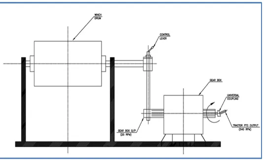
Fig 01: General Arrangement of the Winch System
I.
Basic load calculation
We have consider 4 Mt load for the lifting through this winch system. Maximum load of mass to be lifted = m = 4 Mt = 40000 N
© 2019, IRJET | Impact Factor value: 7.211 | ISO 9001:2008 Certified Journal
| Page 3522
II.
Selection of Rope
[3,4,5,6,18]
As per the specifications, standard wire rope size of nominal diameter 12 mm and type 6 ×19 with steel core is selected. This wire rope has tensile strength and minimum breaking force equal to 1800 MPa and 73.6 KN respectively
Efficiency of wire rope when it is bent around rope drum, η = 0.94 Consider 4 sieve pulley arrangements
Thus, tension in wire rope P = Load to be lifted / (4 *0.94) = 40585/3.76
= 10793.19 N
This value must have to be lesser than the safe working load Recommended factor of safety for general rope applications fs = 6 Safe working load = SWL
= Fb/fs = 73600/6 = 12266.67 N
Hence, tension in the wire rope < safe working load. The selected wire rope is safe and acceptable. Now, each wire diameter in wire rope = 0.45 d = 0.45 × 12
= 5.43 mm
Metallic area of wire rope = 0.40 = 0.40 ×
= 57.6
III. Design of Winch Drum:
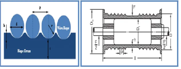
[image:3.595.142.459.490.612.2]Diameter & Groove size
[3,2,18]
Fig 02: Dimension of Rope drum As per IS specification D/d ratio shall not be less than 18
Select D/d= 27 for further calculations
Thus following dimension parameters of rope drum are required to be calculated. Inner diameter of rope drum at bottom of groove, D = (D/d ratio) × d = 27 × 12 = 324 mm Minimum radius of groove, r = 0.53 × d
= 0.53 × 12 = 6.36 mm Minimum depth of groove h = 0.35 × d
= 0.35 × 12 = 4.2 mm ≡ 4 mm Outer diameter of rope drum Do = D + (6d)
= 324 + (6x12) = 396 mm
© 2019, IRJET | Impact Factor value: 7.211 | ISO 9001:2008 Certified Journal
| Page 3523
= 1.08 × 12= 12.96 mm
IV.
Minimum no. of wire rope turns on rope drum
,[3]
n =
= 110000 / (3.14 x 324) +2 = 110 turns
Length of drum, l
l = = 892.54 mm
V.
Thickness of drum
[3,8,19]
Assume thickness of drum = 30 mm Based on the DNV design codes:
The hoop stress in the winch drum, = hoop stress in winch drum (MPa),
T = Load on the rope, Newton d = diameter of the rope, mm. t = thickness of winch drum, mm
C = 1 for 1 layer & 1.75 for more than 1 layer
According to the guidelines, the maximum permissible hoop stress should not exceed 80% of the material yield stress ( 6y).
In this case, the material yields stress. Selecting grey cast iron G4000 with yield stress 276MPa
Hoop stress in the winch drum,[3,18,17]
=
= 197.28 Mpa
Permissible hoop stress = 0.80 x 276 = 220.80 Mpa
Stresses developed on the drum [3,17,18]
Crushing Stress =
= 40585 / (30 x 12.96) = 104.38 MPa
Torque on rope drum
= T =
= 40585 + (324+12)/2 = 40753 N-mm = 40.75 N-m
Selection of the shaft [3,7,9,18]
Selecting the diameter of Indian standard code ds=20mm Transmissible torque value
=
= 61.61 N-m
Here, transmissible torque value > torque on rope drum. Thus, the shaft is acceptable.
© 2019, IRJET | Impact Factor value: 7.211 | ISO 9001:2008 Certified Journal
| Page 3524
[image:5.595.156.444.117.258.2]VI.
Check for fleet angle
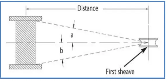
Fig 03: Fleet angle
Fleet angle is the angle between the wire rope and imaginary line extending perpendicular to the drum. The fleet angle varies with the distance between the lead sheave and the drum. The proper fleet angle helps the wire rope to wind evenly onto the drum, and helps to reduce wear to the wire rope, drum, and lead sheave. Too large a fleet angle will cause the wire rope to wind loosely, overlap and possibly jump the flange and cause severe damage to the equipment. A maximum fleet angle of 0.5° to 1.5° for smooth drums, and 2° for grooved drums, helps the wire rope wind uniformly.
By setting up the winch machine 30 meter away from under tower.
Tan A = 0.447/30 Fleet angle A = 0.85° Hence OK
VII. Selection of worm gear box
[20,21]
Fig 04: Worm Gear Box Work= Force x distance = 40585 x 110 = 4464350 N-m
Power= Work/Time
=4464350/300 (@ 20 m/min hence, for 90 meter 300 sec) =14881.16 N-m/sec (14.88 KW)
Torque = Force x Radius of drum = 40585 X 0.162
=6574.77 N-m
Ratio required = input speed/ output speed = 500/25 = 20:1
=nearest standard available ratio 20:1
Lifting load with moderate shock Mechanical service factor = 1.25 (From data table for 8 hr/day) =Equivalent output power (Mechanical) = 14.88 *1.25 = 18.6 Kw
=Equivalent output torque (Mechanical) = (6574.77*18.6)/25 = 4891.62 Nm Thermal service factor = 1.62 (From data table for 50⁰ C)
Equivalent output power (Thermal) = 14.88 *1.62 = 24.10 Kw
Equivalent output torque (Thermal) = (4891.62 *24.10)/25 = 4715.52 Nm Refer at input ratio 20:1 at input speed of 500 rpm, as per calculation we
© 2019, IRJET | Impact Factor value: 7.211 | ISO 9001:2008 Certified Journal
| Page 3525
ratio 20:1 having output mechanical torque = 8423.1 Nm. and input power 21.00 KWRequired input power = (Calculated equivalent torque x rated input power) /(rated output torque x service factor ) = (6574.77 x 14.88) / (4891.62x 1.25) =16 KW Available input source can easily produce required power hence OK
5. COMPUTER AIDED MODEL
With reference to above calculations, all dimensions of assembly are determined. Hence, a computer aided model is prepared in CATIA V5 software in assembly mode. The components of assembly are shown in fig
[image:6.595.181.415.275.460.2]1. Created body part with PAD Command in CATIA with file format .CAT 2. Created shaft with pad command in CATIA with file format .CAT 3. Created rope drum with shaft command in CATIA with file format .CAT 4. Assembled parts in assembly environment by using assembly constraints. 5. Save file in IIGES Format (initial graphics exchange specification)
Fig 05: 3D model of winch system arrangement
6.
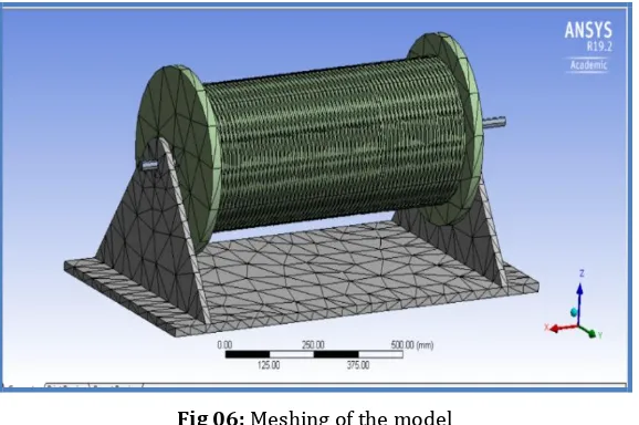
FINITE ELEMENT ANALYSIS
[1,3]
The finite element analysis is carried out by applying load in wire rope along middle turns grooves as the material load is assumed to be lifted by 100 meters and held in to position. The value is 42 N.
Fig 06: Meshing of the model
[image:6.595.155.444.552.744.2]© 2019, IRJET | Impact Factor value: 7.211 | ISO 9001:2008 Certified Journal
| Page 3526
Fig 07: Maximum stresses on drum
Fig 08: Maximum shaft deflection
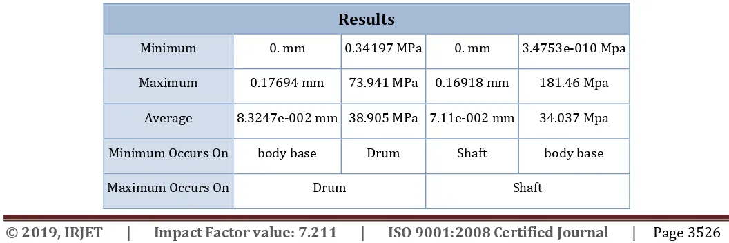
Finite element analysis of assembly shows that, maximum stress condition on the rope drum and shaft shown in Fig. 07 & 08. The values are within limit it means the system is safe in the load condition.
7.
CONCLUSIONS
Finite element analysis is conducted by using ANSYS on rope drum and shaft. Static structural analysis such as modal analysis is conducted. The Vonmises stresses along with the deformations are obtained as post processed results from ANSYS are indicating that the Rope drum is obtaining the Vonmises stress a value of 181.46 N/ which is does not exceeding the permissible hoop stress 220.80 N/
[image:7.595.32.560.618.794.2]The results obtained from Table Nos. 01 and graphs represented Chart: 01& 02, the maximum hoop stress 276 Mpa of the drum fabricated from gray iron G4000 & maximum permissible deflection of the shaft with gear mounting is 1 mm whereas analysis shows maximum deflection of 0 .16mm. For the both analysis i.e rope and shaft achieved within limits
Table -1: FEM Results
Results
Minimum 0. mm 0.34197 MPa 0. mm 3.4753e-010 Mpa
Maximum 0.17694 mm 73.941 MPa 0.16918 mm 181.46 Mpa
Average 8.3247e-002 mm 38.905 MPa 7.11e-002 mm 34.037 Mpa
Minimum Occurs On body base Drum Shaft body base
© 2019, IRJET | Impact Factor value: 7.211 | ISO 9001:2008 Certified Journal
| Page 3527
Chart -1: Stresses on the Rope DrumChart -2: Deflection of shaft in loading condition
ACKNOWLEDGEMENT
I would like to thank my guide Prof. Dr. Gawande Rupesh (Associate. Prof. at BDCOE Sewagram) and advisor Mr.Fulmali S.M (Asst. Prof. at B.D.C.O.E, Sewagram) who provided extensive guidance in many times of need and sharing of knowledge. I would like to thank my parents for their motivation and supports
REFERENCES
[1] D.V. Hutton, Fundamentals of Finite Element Analysis, The McGraw-Hill Companies Inc. ISBN: 0-07-112231-1, 2004
[2] V.B. Bhandari, Design of Machine Elements, Edition: 2, Tata McGraw-Hill Publishing Company Limited, New Delhi, ISBN: 0-07-061141-6, 2008
[3] Design and Finite Element Analysis of Rope Drum and Drum Shaft for Lifted Material Loading Condition-Patil,K.Narkar IERJ Special Issue 2 Page 2034-2040, 2015, ISSN 2395-1621
[4] IS 2266 (2002): Steel Wire Ropes for General Engineering Purposes, Indian Standard, Bureau of Indian Standards,
© 2019, IRJET | Impact Factor value: 7.211 | ISO 9001:2008 Certified Journal
| Page 3528
[5] IS 6938 (2005): Design of rope drum and chain hoists for hydraulic gates - Code of practice, Indian Standard, Bureauof Indian Standards, November 2005.
[6] IS 3938 (1983): Specification Electric Wire Rope Hoists, Indian Standard, Bureau of Indian Standards, August 1997.
[7] IS 3688 (1990): Power transmission - Shafts - Dimensions for cylindrical and 1/10 conical shaft ends, Indian Standard, Bureau of Indian Standards, November 1990.
[8] S.Mangalekar, V.Bankar, P.Chaphale, Design and Analysis of Central Drum Mine Hoist IRJET journal Volume: 03 Issue: 06 | June-2016
[9] S.P. Raut, L.P. Raut, Failure Analysis and Redesign of Shaft of Overhead Crane, International Journal of Engineering Research and Applications, ISSN: 2248-9622, Volume: 4, Issue: 6, Version: 3, Page No.: 130-135, June 2014
[10] Moses Frank Oduori and Thomas Ochuku Mbuya,Wire Rope Selection for Manual Winch Application, School of
Engineering, The University of Nairobi, Journal of Engineering, Design and Technology, Vol. 7 No. 2, 2009.
[11] A.K. Patel, V.K. Jani, Design and Dynamic Analysis of 70T Double Girder Electric Overhead Crane, Journal of
Information, Knowledge and Research in Mechanical Engineering, ISSN: 0975-668X, Volume: 2, Issue: 2, Page No.: 496-503, October 2013.
[12] Joey McKee, Design, construction, and evaluation of a hydraulic powered PTO winch, Bio Resource and Agricultural
Engineering Bio Resource and Agricultural Engineering Department California Polytechnic State University San Luis Obispo 2011
[13] Lim Buan Teck,AM16 Improvement in the design of winch -, National University of Singapore
[14] Dr Markus van der Laan ,Safe Winch tackles slack wires and peak loads For practical use in harbour towage and escorting, Paper 2, Southampton, UK Organised by the ABR Company Ltd,2008.
[15] P.F.Cabral, Traction Winch Design, Calculation & analysis.
[16] Amit Tiwari, Design and fabrication of double acting winch type elevator,IJMER,2015
[17] Dietz, Design criteria for multilayer wound winch drums following lightweight design principle ,International Design
Conference 2004
[18] Machine design data book, Downloaded from Digital Engineering Library @ McGraw-Hill
(www.digitalengineeringlibrary.com)
[19] Michael Markey, Single drum winch design, Naval Research and the National Science Foundation, Third edition 2000
[20] Design data book – B.D.Shivalkar