© 2019, IRJET | Impact Factor value: 7.211 | ISO 9001:2008 Certified Journal
| Page 4632
ANALYSIS ON THREAD ROLLING USING FLAT DIES
Katta Udaya
1, K.Kishore
2, S.Sreekrishna
31
PG Student, Department of Mechanical Engineering, Vasavi College of Engineering, Telangana,5000031, India
2
Professor, Department of Mechanical Engineering, Telangana, 5000031, India
3
Assistant Professor, Department of Mechanical Engineering, Telangana, 5000031, India
---***---Abstract -
Threads are used for joining two or more parts inan assembly. Threads are traditionally made by material removal process due to which a lot of scraps is generated. To minimize the wastage and to get better mechanical properties thread rolling process replaces the thread cutting process. This process plays a critical role in fasteners and has been applied to the automobile industry, construction industry, and aerospace industry.
Thread rolling is a cold forging process where the blank is passed between the two flat dies to form the required threads. Reciprocating motion is used in this process for the movement of the die. The aim of the study is to generate the threads using the reciprocating motion of the shaper machine with the consideration of the parameters like various blank diameters of aluminum material, to find the rolling load, the power consumption of the shaper machine. Then the theoretical and
experimental values were compared and by usingcomputer
simulation (ANSYS WORKBENCH 18.1) this study also attempts to analyze the stresses, deformation behavior of the assembled model and the results were compared.
Key Words:Flat dies, Manufacturing of threads by thread rolling, Shaper machine, Analysis.
1. INTRODUCTION
Thread forming and thread rolling are processes for forming screw threads. Thread rolling is a cold-forming process operation in which the threads are formed by rolling a thread blank between hardened dies that cause the metal to flow radially into the desired shape. One of the most efficient systems for the generation of external threads is precisely the thread rolling. Thread rolling is a metal rolling process used extensively in the manufacturing industry to produce screws, bolts, and other fasteners. A common thread rolling process, used in industry to manufacture threaded parts, involves forming the threads into the metal of a blank by a pressing and rolling action between two dies. The die surfaces hold the shape and the force of the action forms the threads into the material. Thread rolling process is now widely acknowledged as the fastest and most efficient method of producing accurate external threads, with surface finish and mechanical properties unobtainable by any other method. In addition, because of cold working, the threads have greater strength than cut threads, and a smoother, harder and more wear resistant surface is obtained.
Thread rolling is different from other types of threading processes like cutting, grinding, and chasing. Thread rolling is widely used for mass production of fasteners like bolts, screws, etc. This process is used for large production runs because typical production rates are around one piece per second. Rolling produces no swarf and less material is required because the blank size starts smaller than a blank required for cutting threads, there is typically a 15 to 20% material savings in the blank, by weight. A rolled thread can often be easily recognized because the thread has a larger diameter than the blank rod from which it has been made; however, necks and undercuts can be cut or rolled onto blanks with threads that are not rolled. Also, the end of the screw usually looks a bit different from the end of a cut-thread screw. Materials are limited to ductile materials because the threads are cold formed. However, this increases the thread's yield strength, surface finish, hardness, and wears resistance. Also, materials with good deformation characteristics are necessary for rolling these materials include softer (more ductile) metals and exclude brittle materials, such as cast iron.
Fig-1: Flat thread rolling dies
© 2019, IRJET | Impact Factor value: 7.211 | ISO 9001:2008 Certified Journal
| Page 4633
1.1 Types of dies used for thread rolling process
There are three main types of dies used in thread rolling machines:
i.Flat dies and ii. Two-die cylindrical iii. Three-die cylindrical
Flat dies are rectangular, simple contour dies that are typically used for machined metal screws, thread tapping, and woodscrews. All the flat dies are made of hardened cold die steel and provided with linear parallel threads like grooves of geometry as that of the desired thread. Cylindrical dies can have two or three in-feeds, meaning two or three areas of insertion. Cylindrical two-feed dies are often used for large or balanced screws, while cylindrical three-feed dies are used in applications such as tube fittings or spark plugs.
1.2 Materials used in thread rolling
Thread rolling requires materials that have good deformation properties, including highly ductile metals such as aluminum rod and copper and excluding brittle materials such as cast iron.
2. SCOPE OF WORK
The present work aims at producing the threads by thread rolling process using the reciprocating motion of shaper machine. The experiment is done using flat dies considering High-Speed Steel (HSS) as die material and blank or workpiece material as Aluminium and the experimental values are calculated like rolling load, stresses, speed, power, etc. The Flat die, die holding setup is modeled in NX11.0 and the CAD model is exported and analysis is done in ANSYS 19.1(WORKBENCH) to obtain the stress, strain and deformation values and compared with experimental values.
3. EXPERIMENTAL STUDY
The materials used in this experiment are High-Speed Steel (HSS) as flat die material and aluminum for workpiece/blank.
3.1 Workpiece Preparation.
The diameter of workpieces-6mm, 8mm, 10mm, 12mm, 14mm, 16mm.
Length of the workpiece is 30 mm.
3.2 Specification of Apparatus used for thread formation Machine→ Horizontal shaper machine
Motor → 3HP
Die → Flat Reciprocating die
Die material → High-Speed Steel(HSS) Length of die → 104mm
3.3 Experiment Procedure
The die holding is inserted in the tool post of the shaper machine and the other die is fixed to the bed of a machine. Under different load conditions, with constant velocity, the workpieces are placed between the dies of various diameters to form the required threads on each blank and the dial gauge is placed opposite to the moving die to note down the deflection values for each diameter of the workpiece as shown in fig 3.
To find how much amount of load is applied on each workpiece, proven ring experiment (fig 3.1) is conducted where the moving die which has an attachment is taken and it is fixed at one end and the loads are placed on free end until the required deflection value is obtained. So for thread rolling experiment deflection values, the loads are found which is listed in table 3.1
© 2019, IRJET | Impact Factor value: 7.211 | ISO 9001:2008 Certified Journal
| Page 4634
THREAD ROLLED WORKPIECES
6mm 8mm 10mm 12mm
14mm 16mm
Fig-3.1: Proven Ring Experiment to find the load
S.NO The diameter of
the workpiece
(mm)
Deflection
(mm)
Load
(kg)
1. 6 1.86 157
2. 8 2 160
3. 10 2.1 168
4. 12 2.2 176
5. 14 2.25 180
6. 16 2.5 200
Table- 3.1: Experimental results of deflection and load values for each diameter of the workpiece
© 2019, IRJET | Impact Factor value: 7.211 | ISO 9001:2008 Certified Journal
| Page 4635
power consumption, Stresses were calculated for eachthreaded workpiece and observed that thread rolling can be done up to 14mm diameter workpieces using this shaper machine. So the experiment successfully can be done for 4mm diameter to 14mm diameter workpieces. The below table(3.2) shows the power consumption required for each diameter of the workpiece.
Power consumption
( KW)
Stress [σ=FH/r×δθ×L]
(Mpa)
1.38
171.13
1.41
130.8
1.48
109.87
1.55
95.92
1.58
84.08
1.7
81.75
Table -3.2: Power consumption and stresses
4. MODELLING AND ASSEMBLY OF FLAT DIE AND
WORKPIECE
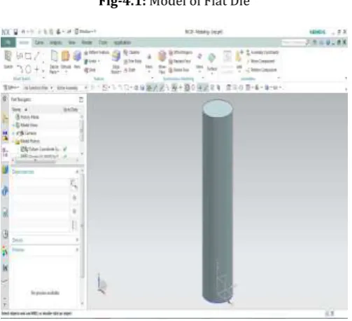
[image:4.595.309.561.105.334.2]The Flat die fixed die used in the experiment and different size diameter workpieces are modeled according to the dimension using design software NX11.0 as shown in the figs.4.1, 4.2 and using assembly module the modeled parts are assembled as shown in fig.4.3
[image:4.595.31.293.189.411.2]Fig-4.1: Model of Flat Die
[image:4.595.321.546.372.487.2]Fig -4.2: Model of the workpiece
Fig-4.3: Assembly of flat die and workpiece
5. STATIC STRUCTURAL ANALYSIS
The developed model of the Flat die and workpiece is imported into the static structural module of ANSYS workbench 19.1 platforms for structural analysis.
The static structural analysis of the Flat die and the workpiece is done by the following steps:
i. Feeding the required material data in the engineering data sheet.
ii. Importing the model into the geometry and assigning the material properties
iii. Meshing the model.
iv. Assigning the boundary conditions and solving. v. Analysis settings, mesh size, and boundary
[image:4.595.45.562.571.787.2]© 2019, IRJET | Impact Factor value: 7.211 | ISO 9001:2008 Certified Journal
| Page 4636
5.2 Material data
The required material data of high-speed steel (flat die), Aluminum (blank) and material properties were fed into the engineering data sheet of the static structural module.
5.3. Flat die and blank material properties
Material
Density(g/cm3)
Young’s
modulus
Poisons
ratio
(Mpa)
High Speed
Steel
8.16
12.26e+05
0.29
Aluminum
2.7 g/cm3
62000
0.33
5.4. Meshing
The meshing of the flat die and workpiece was done with the following data and the meshed model is shown in fig-5.1
[image:5.595.308.560.99.271.2]Element type: triangular, element size: 5.4561mm
Fig- 5.1 Meshed dies and workpiece
5.5. Boundary conditions
The bottom side of the flat die was fixed and the force is applied on the blank.
[image:5.595.311.561.385.506.2]Force / Feed: 0, -1726.56, 0 (x, y, z) [for 12mm diameter]
Fig-5.2 Boundary conditions
6. RESULTS
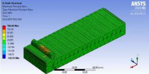
[image:5.595.35.291.509.639.2]Analysis results like equivalent stresses, maximum principal stresses, and total deformation were obtained and listed in table 6.4
Fig-6.1: Total deformation of 6mm blank
Fig-6.2: Maximum Principal Stress of 6mm blank
[image:5.595.308.563.534.660.2]© 2019, IRJET | Impact Factor value: 7.211 | ISO 9001:2008 Certified Journal
| Page 4637
The diameter of a workpiece(mm) Force (N) Maximum total deformation (mm) Maximum Principal Stress (Mpa)
6 1540.17 0.07 166.66
8 1569.6 0.11 125.36
10 1648.08 0.12 96.70
12 1726.56 0.17 90.89
14 1765.8 0.20 80.88
[image:6.595.37.317.369.606.2]16 1962 0.25 77.63
Table -6.3: Maximum principle stress and total deformation of die and workpiece.
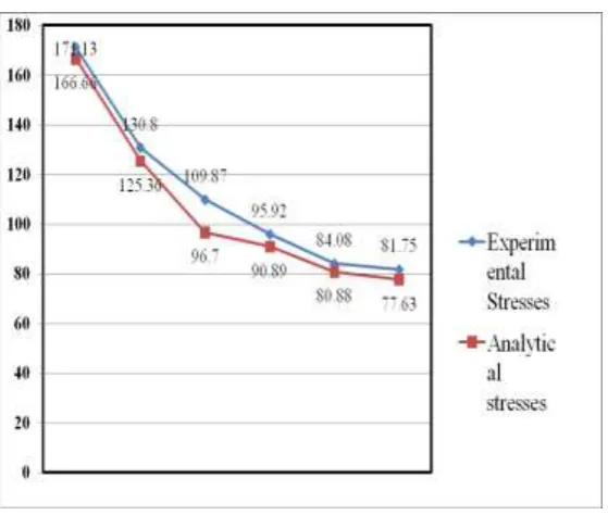
Chart-2: Experimental and analytical stresses
7. CONCLUSION
From the experiment, thread rolling can be done for smaller diameter workpieces up to 16mm for a 3HP motor. So we can conclude that threads can be formed on large diameter workpieces depending on the motor power. The minimum size of the blank for which thread rolling can be done is on 6mm based on the strength of the material. Finally, the experimental and analysis results were compared.
REFERENCES
1. Darth. S, Ramesh Babu K and Manjunath S "Comprehensive Study of Cut and Roll Threads". IOSR Journal of Mechanical and Civil Engineering (IOSR-JMCE) e-ISSN: 2278-1684,p-ISSN: 2320-334X, Volume 11, Issue 2 Ver. VI (Mar-Apr. 2014) 2. Ajay Bangar, Abhay Pratap Singh, Sanjay Goyal
"Design analysis of externally threaded bolts manufactured by flat reciprocating die with the help of Taguchi optimization technique" International journal of advanced scientific and technical research Issue 2 volume 6, December 2012
3. Shigeru Yamanaka, Kenji Amiya, Yasunori Saotome and Akihisa Inoue, “Plastic Working of Metallic Glass Bolts by Cold Thread Rolling” Materials Transactions, Vol. 52, No. 2 (2011) pp. 243 to 249 4. Shao-Yi Hsia, Yu-Tuan Chou and Guan-Fan Lu
"Analysis of Sheet Metal Tapping Screw Fabrication Using a Finite Element Method" Applied sciences volume 4 June 2016.
5. PS Chauhan, C M Agrawal, R K Dwivedi, "Effect of material and process parameter on dimensions of rolled external threads" Applied Mechanics and Materials ISSN: 1662-7482, Vol. 493, pp 453-460 6. O.S. Zhelezkov, S.A. Malakanov, V.V. Semashko “Prediction of Thread Rolling Tools Wear Resistance” International Conference on Industrial Engineering, ICIE 2017.
7. Shao-Yi Hsia and Shuo-Kai Pan, Yu-Tuan Chou “Computer Simulation for Flat-die Thread Rolling of Screw” of International journal of advanced scientific and technical research Issue 2 volume 4, December 2016
8. A Yu Popov, I A Bugay, P V Nazarov, O P Evdokimova, P E Popov and E V Vasilyev "Research of thread rolling on difficult-to-cut material workpieces" IOP Conf. Series: Journal of Physics: Conf. (2017).
9. Isamu Yoshimoto “The Rolling Pressure Of Flat Die Type” JSME Vol.2, No.7, 1958.
10. Milan Dvořák, Jaroslav Prokop “Theoretic and technological aspects of thread rolling” Journal for Technology of Plasticity, Vol. 25 (2000), Number 12. 11. Z. Pater, A. Gontarz, W. Weroñski “New method of thread rolling” Journal of Materials Processing Technology · November 2004
12. Krzyszt "Numerical modeling of strain and stress states in quick thread cold rolling process" vol. 58.2012.
13. Hemanth S Thulasi “Design and Manufacturing Simulation of Preform for Thread Rolling Operation” International Journal Of Modern Engineering Research (IJMER) Vol. 5 Iss. 10 October 2015.
© 2019, IRJET | Impact Factor value: 7.211 | ISO 9001:2008 Certified Journal
| Page 4638
process with round dies" Mechanism and MachineTheory, ELSEVIER November 2016.