Dyke Award
Jeremy B. Rubin 1 Dieter
R.
EnzmannThis article appears in the March/April 1987 issue of AJNR and the May 1987 issue of AJR.
Received March 31, 1986; accepted after revi-sion September 16, 1986.
Presented at the annual meetings of the Ameri-can Society of Neuroradiology, San Diego, January 1986, and the Western Neuroradiological Society, Monterey, CA, October 1985.
1 Both authors: Department of Radiology, Stan-ford University School of Medicine, Stanford, CA 94305. Address reprint requests to J. B. Rubin. AJNR 8:307-318, March/April 1987
0195-6108/87/0802-0307
© American Society of Neuroradiology
Harmonic
Modulation
of
Proton
MR
Precessional
Phase
by
Pulsatile Motion:
307
Origin of Spinal CSF Flow
Phenomena
The effects of pulsatile motion on MR imaging of spinal CSF were quantitatively evaluated with a spine phantom that simulated spinal CSF pulsation. Two fundamental interdependent pulsation flow phenomena were observed: variable reductions in signal intensity of pulsatile CSF (signal loss) and spatial mismapping of this signal beyond the confines of the subarachnoid space (phase-shift images). Phase-shift images were observed as multiple regions of signal intensity conforming morphologically to the subarachnoid space but displaced symmetrically from it along the phase-encoding axis, either added to or subtracted from stationary signal intensity. Both CSF pulsation flow phenomena occurred secondary to harmonic modulation of proton precessional phase (temporal phase shift) by the unique pulsatile motion of spinal CSF when the repetition time was not an integral multiple of the pulsation period. Each flow phenomenon was analyzed with the spine phantom independently to control individual imaging and physiologic parameters including imaging plane, repetition time, echo time, slice thick-ness, number of echoes, number of excitations, CSF pulsation amplitude, and CSF pulsation period. In the axial plane, signal loss was present on both first- and second-echo images and was more pronounced with larger pulsation amplitudes and smaller slice thicknesses. A quantitative relationship between these two parameters allowed the prediction of CSF pulsation amplitude when the slice thickness was known and the
CSF signal intensity was measured. In the sagittal plane, signal loss was present on first-echo images, was more pronounced with larger pulsation amplitudes, and under-went incomplete even-echo rephasing on second-echo images. Phase-shift images were influenced by the relationship between repetition time and CSF pulsation period. They were partly eliminated on sagittal but not on axial second-echo images because of incomplete even-echo rephasing. Both signal loss and phase-shift images were
completely eliminated with CSF gating or pseudogating, indicating the rationale for gating during clinical spinal MR. The clinical significance of these findings is that awareness of the existence of spinal CSF pulsation flow phenomena avoids diagnostiC confusion, whereas understanding their etiology provides a rational approach, such as CSF gating, to eliminate them.
As described in part 1 of this article [1], CSF pulsation flow phenomena are
present in normal individuals, and their absence may signify pathologic conditions associated with spinal block. In addition, the interpretation of spinal MR images may be difficult because of complex subarachnoid signal-intensity patterns created by pulsatile CSF motion. Understanding the manifestations and mechanisms of
308
RUBIN AND ENZMANN AJNR:8, March/April 1987controlled independently and the relationships between phys-iologic and MR data acquisition parameters investigated.
Materials and Methods
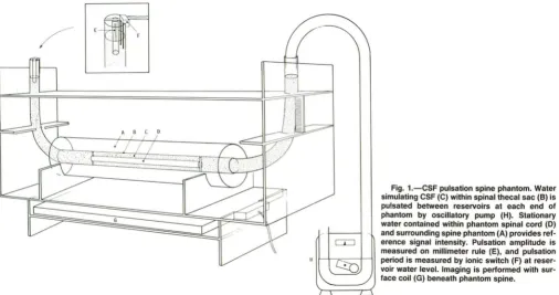
The spine phantom was constructed of three concentric acrylic
tubes (Fig. 1). The innermost tube (phantom spinal cord) had a
1.6-cm outer diameter (00) and 25-1.6-cm length and contained stationary
water that served as a reference signal intensity during imaging. The
middle concentric acrylic tube (phantom thecal sac) had a 2.5-cm
inner diameter (10) and 46-cm length and was connected at each end to vinyl tubing (2.5-cm 10, 30-cm length) formed to resemble a J-shaped reservoir. Water contained between the middle and inner-most tubes (phantom CSF) was oscillated between these reservoirs
to simulate CSF pulsation using a periodic pneumatic pressure
pro-duced by a dual-roller blood pump (Gambro BPl 0-1 C, Sweden) modified by removing one of the rollers. Independent control of pulsation amplitude and period on a continuous spectrum was
ac-complished by adjusting the blood-pump roller-tension screw and
flow-rate potentiometer, respectively. Stationary water contained
be-tween the middle and outermost acrylic tube (7.6-cm 00, 38-cm
length) was used to simulate perivertebral soft tissues. A rigid stand was constructed to position the phantom spine at the magnet
iso-center and prevent motion during imaging.
Pulsation amplitude was measured directly from the reservoir water level, which was displaced by a segment of acrylic tubing equal in diameter to the phantom spinal cord. Pulsation period was measured to within several milliseconds with a digital oscilloscope (Tektronix Model 468, Beaverton, OR) connected in series between a 5-V DC power supply and dual electrode leads (ionic switch) fixed at water level within the reservoir. Using this circuit as a trigger, direct "CSF gating" of MR data acquisition was synchronized to "systole" or "diastole" by adjusting the electrode lead height in relation to the reservoir water level.
A GE Signa superconducting MR system operating at 1.5 T and equipped with a 30- by 18-cm rectangular surface coil was used for
phantom spine imaging. Image reconstruction was done with 20FT techniques. Image matrix size was 256 in frequency and 128 in phase-encoding directions resulting in a pixel resolution of 0.6 x 1.2 mm for a 16-cm field of view. Short- and long-TR spin-echo pulse sequences were used in both axial and sagittal planes in conjunction with single- or multislice and single- or multiecho acquisitions. A single echo at TE 25 msec was obtained for short TR (400-1000 msec) sequences, while two echoes at TE 40 and 80 msec were obtained for long TR (2000-3000 msec) sequences. Between two and 10 excitations were acquired for each imaging sequence.
The effects of slice thickness (3, 5, 10, 15, and 20 mm) and pulsation amplitude (3, 8, 16, and 32 mm) on CSF pulsation flow phenomena were quantitatively evaluated in both axial and sagittal planes (TR 2000 msec; TE 40, 80 msec; slice spacing 1 mm; pulsation period 1056 msec). The influence of slice spacing in the axial plane on these results was then investigated by repeating the experiments using a slice spacing (0.6, 1, 2, 3, or 4 mm) equal to 20% of the slice thickness (3,5, 10, 15, or 20 mm). In addition, constant slice thickness (5 mm) and pulsation amplitude (10 mm) were used in the axial plane with increasing slice spacing (0.6, 2.4, 4.5, or 9 mm). The effects of TE (25,50,75, and 100 msec) independent of echo number on CSF pulsation flow phenomena were quantitatively evaluated in the sagittal plane by using two echoes (TR 2000 msec, slice thickness 3 mm, pulsation amplitude 10 mm, pulsation period 1056 msec). In each image, signal intensity (pulsatile and stationary water) and phase-shift images (number, position, and signal intensity) were evaluated. The percentage signal intenSity of pulsatile to stationary water was calculated for each image by using regions of interest within the phantom subarachnoid space and spinal cord. Signal nonuniformity caused by surface-coil imaging was avoided by choosing region-of-interest locations equidistant from the surface coil on control images obtained without phantom CSF pulsation (pump off).
The effects of TR and pulsation period on CSF pulsation flow
phenomena during axial and sagittal single-slice imaging were eval-uated by three methods (pulsation amplitude 10 mm, slice thickness 5 mm, TE 25 msec). First, using a constant pulsation period (1056 msec), TR was systematically increased from 150 to 3000 msec (TR
Fig. 1.-CSF pulsation spine phantom. Water simulating CSF (e) within spinal thecal sac (8) is pulsated between reservoirs at each end of phantom by OSCillatory pump (H). Stationary
water contained within phantom spinal cord (0) and surrounding spine phantom (A) provides
[image:2.613.55.561.470.737.2]AJNR:8, March/April 1987 HARMONIC MODULATION OF PROTON MR PRECESSIONAL PHASE
309
150-1000 msec in 50-msec increments, TR 1000-3000 msec in 100-msec increments). The second method used pseudogating (inten-tional synchronization of TR with pulsation period) with the TR equal to an even multiple (0.5, 1, 2) of the pulsation period (1056, 1500 msec). For each multiple, TR was systematically varied from this value by 2- to 1 O-msec increments. The third method was CSF gating of MR data acquisition and comparison of these results with nongated and pseudogated images obtained under otherwise identical condi-tions (TE 25 msec, slice thickness 5 mm, pulsation period 1500 msec, pulsation amplitude 10 mm).
Results
In the absence of pulsatile motion, water within the phantom subarachnoid space was equal in signal intensity to the
ad-jacent control water (Figs. 2A and 3A) provided that
region-of-interest measurements were made equidistant from the surface coil. During axial and sagittal imaging of pulsatile motion, two interdependent flow phenomena were observed
(Figs. 2 and 3): decreased signal intensity of oscillating water
(signal loss) and multiple regions of signal intensity conforming morphologically to the subarachnoid space but displaced symmetrically from it along the phase-encoding axis
(phase-shift images). The manifestations of these two flow
phenom-ena were dependent on pulsation period, pulsation amplitude,
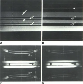
Fig. 2.-Pulsation flow phenomena, sagittal spine phantom. All pulse sequences had TR 2000 msec, slice thickness 3 mm.
A, Control. Pulsation pump off, TE 40 msec, field of view 16 cm. Homogeneous signal inten-sity within all compartments: subarachnoid space (curved arrows), spinal cord (short
straighf arrow), and surrounding control water
(long straight arrow). Acrylic walls of phantom spinal cord and thecal sac are low signal inten-sity. Signal gradient from bottom to top of image occurs because of surface-coil imaging.
B, Signal loss. Pulsation amplitude 20 mm, pulsation frequency 1056 msec, TE 40 msec, field of view 16 cm. Decreased signal intensity of pulsatile water within subarachnoid space
(open arrows). Phase-shift images are projected outside of spine phantom (solid arrow).
C, Phase-shift images. First-echo image, pul-sation amplitude 10 mm, pulpul-sation frequency 1056 msec, TE 40 msec, field of view 48 cm.
A
Phase-shift images (arrows) are morphologically identical to subarachnoid space but displaced symmetrically from it along phase-encoding di-rection (curvilinear distortion is apparent only when large fields of view are used). Signal loss within subarachnoid space persists. Rectangular regions of decreased signal intensity at each end of spinal cord are acrylic plugs. Ovoid region of decreased signal intensity within spinal cord on reader's right is an air bubble.D, Incomplete even-echo rephasing.
Second-echo image, pulsation amplitude 10 mm, pulsa-tion frequency 1056 msec, TE 80 msec, field of view 48 cm. Signal intensity of pulsatile water within subarachnoid space is greater than on first-echo image (C) but is still less intense than stationary control water. Phase-shift images are much less apparent than on C. Even-echo re-phasing was not observed during axial imaging.
c
imaging plane, TR, TE, slice thickness, number of echoes,
number of excitations, and field of view.
Signal loss was uniform across the flow-channel lumen
except for the frequent presence of a thin rim of signal intensity isointense with control water at the interface with
the walls of the spine phantom (Fig. 3C). Pulsatile water signal
intensity was nonuniform only when superimposition by
phase-shift images occurred. Individual phase-shift images
were discrete and sharply marginated, and their morphology
was identical to that of the pulsatile water within the
subarach-noid space on both axial and sagittal images (Figs. 2 and 3).
The spacing between individual phase-shift images was equal,
whereas their signal intensity varied with their displacement from the flow channel. Where the phase-shift images pro-jected beyond the confines of the phantom into air, their signal intensity was always symmetric about the flow channel (Fig.
3D). Where phase-shift images coexisted spatially with
sta-tionary (reference) water, the resulting signal intensity was
asymmetric about the flow channel. In this case, correspond-ing phase-shift images equidistant from the flow channel demonstrated opposite interference patterns (constructive
and destructive), resulting in the appearance of phase-shift
images added to and subtracted from stationary signal
inten-sity (Fig. 3D).
B
[image:3.612.223.558.392.734.2]310 RUBIN AND ENZMANN AJNR:8, March/April 1987
E
F
Signal loss within pulsatile water was influenced by the imaging plane, TR, pulsation period, slice thickness, pulsation amplitude, echo number, and TE. In both axial and sagittal imaging planes, signal loss was observed when the TR was not an integral multiple of the pulsation period. During axial imaging, signal loss within pulsatile water was present on both first- and second-echo images, and decreasing slice thickness resulted in more pronounced signal loss on both echoes (Figs. 3-5). The signal intensity of pulsatile water approached that of control water on first-echo images with slice thicknesses greater than 1 cm and pulsation amplitudes less than 16 mm (Figs. 3 and 4). Increasing pulsation ampli-tude during axial imaging resulted in more pronounced signal loss on first- and second-echo images (Figs. 4-6). Plotting percentage signal intensity from axial images as a function of slice thickness for each pulsation amplitude studied, pulsatile water varied between 15 and 1 00% of control-water signal
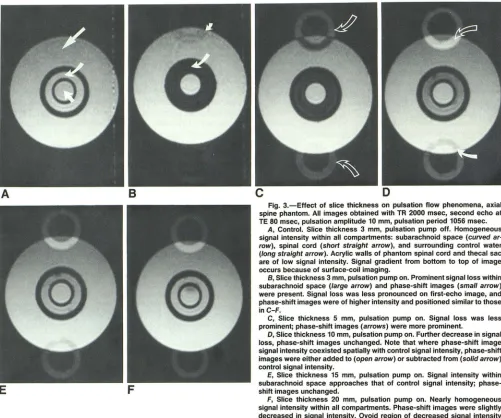
Fig. 3.-Effect of slice thickness on pulsation flow phenomena, axial spine phantom. All images obtained with TR 2000 msec, second echo at TE 80 msec, pulsation amplitude 10 mm, pulsation period 1056 msec.
A, Control. Slice thickness 3 mm, pulsation pump off. Homogeneous signal intensity within all compartments: subarachnoid space (curved ar· row), spinal cord (short straight arrow), and surrounding control water (long straight arrow). Acrylic walls of phantom spinal cord and thecal sac are of low signal intensity. Signal gradient from bottom to top of image occurs because of surface-coil imaging.
B, Slice thickness 3 mm, pulsation pump on. Prominent signal loss within subarachnoid space (large arrow) and phase-shift images (small arrow) were present. Signal loss was less pronounced on first-echo image, and phase-shift images were of higher intensity and positioned similar to those inC-F.
C, Slice thickness 5 mm, pulsation pump on. Signal loss was less prominent; phase-shift images (arrows) were more prominent.
D, Slice thickness 10 mm, pulsation pump on. Further decrease in signal loss, phase-shift images unchanged. Note that where phase-shift image signal intensity coexisted spatially with control signal intensity, phase-shift images were either added to (open arrow) or subtracted from (solid arrow) control signal intensity.
E, Slice thickness 15 mm, pulsation pump on. Signal intensity within subarachnoid space approaches that of control signal intensity; phase-shift images unchanged.
F, Slice thickness 20 mm, pulsation pump on. Nearly homogeneous signal intensity within all compartments. Phase-shift images were slightly decreased in signal intensity. Ovoid region of decreased signal intensity within spinal cord was air bubble now included in slice.
intensity depending on the combination of slice thickness and pulsation amplitude during imaging (Fig. 4). For each combi-nation, signal loss was always more prominent on axial sec-ond-echo images than on first-echo images (Figs. 4 and 5). Plotting percentage signal intensity from axial images as a function of the ratio of pulsation amplitude to slice thickness, a linear decrease in signal intensity occurred at ratios of 0.5-3 (Fig. 7).
[image:4.612.57.558.86.504.2]AJNR:8, March/April 1987 HARMONIC MODULATION OF PROTON MR PRECESSIONAL PHASE 311
Fig. 4.-Graph of first-echo percentage signal intensity (pulsatile to control water) plotted as function of slice thickness for each pulsation amplitude studied. TR 2000 msec, TE 40 msec.
Decreased percentage signal intensity was ob-served with decreasing slice thickness, most pronounced with large pulsation amplitudes (16 and 32 mm). Decreased percentage signal inten-sity was also observed with increasing pulsation amplitudes, most pronounced with thin slices (3 and 5 mm).
100
90
80
70
50
50
40
30
20
10
a +----,----_.----._----._--~----_.----._----r_--~----_r--~
o 4 5 8 10 12 14 15 18 20 22
SLICE THICKNESS (MMI
100
90
% 80
70
50
so
40
30
20
10 Fig. 5.-Graph of second-echo percentage signal intensity (pulsatile to control water) plot-ted as function of slice thickness for each pul-sation amplitude studied. TR 2000 msec, TE 80 msec. Effects of slice thickness and pulsation amplitude on percentage signal intensity were significantly more pronounced than from first-echo data (Fig. 4).
o
+---~r_--~----_.----._----._----r_--_,----_.----._----r_--~a
During both axial and sagittal imaging, when TR was an
integral multiple of the pulsation period, signal loss was
completely eliminated (Figs. BA, BB, and 9C).
Phase-shift images ariSing from pulsatile water were influ
-enced by imaging plane, TR, pulsation period, number of
excitations, pulsation amplitude, slice thickness, and TE. In
both axial and sagittal imaging planes, phase-shift images
were observed when the product of TR and the number of
averaged excitations was not an integral multiple of the
pulsation period. Maximum displacement of phase-shift im-ages from the subarachnoid space occurred when the product
of TR and the number of excitations was either one-half the
pulsation period or equal to the average of consecutive
mul-tiples of the pulsation period. In both planes, as TR
ap-5 8 10 12 14 15 18 20 22
SLICE THICKNESS (MM)
proached an integral multiple of the pulsation period, phase-shift images converged upon the flow channel (Figs. Band 9).
The relationship between TR and pulsation period was critical
because if TR was only 10 or 20 msec offset from an integral
multiple of the pulsation period then considerable separation of the phase-shift images from the subarachnoid space oc-curred, resulting in diminished conspicuity of CSF-spinal cord
and CSF-thecal sac interfaces (Fig. 9). When the product of TR and the number of excitations was an integral multiple of the pulsation period, phase-shift images were completely eliminated (Figs. BA, BB, and 9C). For example, using a TR equal to one-half the pulsation period and two excitations,
[image:5.614.216.559.82.544.2]312 RUBIN AND ENZMANN AJNR:8, March/April 1987
A
B
c
D
Fig. 6.-Effect of pulsation amplitude on pulsation flow phenomena, axial spine phantom. Ali pulse sequences had TR 2000 msec, TE 40 msec, slice thickness 5 mm, pulsation period 1056 msec.
A, Pulsation amplitude 2 mm. Signal intensity was homogeneous within ali compartments. Low-intensity phase-shift images (arrow) were observed
even at this low pulsation amplitude. '
B, Pulsation amplitude 5 mm. Minimal signal loss within subarachnoid space. Phase-shift images slightly more prominent.
C, Pulsation amplitude 10 mm. Increased signal loss within subarachnoid space. Phase-shift images increased in signal intensity although unchanged in position.
D, Pulsation amplitude 20 mm. Marked signal loss within subarachnoid space. Phase·shift images unchanged.
110 ~---,
100
90
80
70
&0 50
40
30
20
10
PULSATION AMPLlTUOE:
3nm
8nm
16 nrn
-+
-
32 Il1Tl\~
-
-
-
[image:6.615.58.561.83.275.2]----+
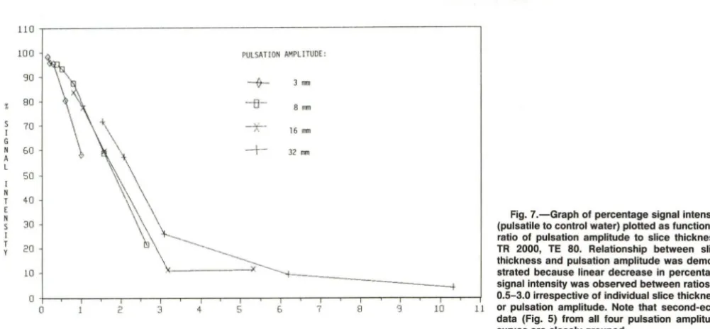
Fig. 7.-Graph of percentage signal intensity (pulsatile to control water) plotted as function of ratio of pulsation amplitude to slice thickness. TR 2000, TE 80. Relationship between slice thickness and pulsation amplitude was demon-strated because linear decrease in percentage signal intensity was observed between ratios of
o +--.,.-- -,..--r----,;--"T"'"""T--.,.---r--,.--,---,.--,---,..--,--,....-,..---,;--,---,---,---r--j 0.5-3.0 irrespective of individual slice thickness
o 2 3 4 5 & 7 8 '3 10 11 or pulsation amplitude. Note that second-echo
RATIO OF PULSATION AMPLlTUOE (MM) TO SLICE THICKNESS
imaging planes using CSF-gated data acquisition (Fig. 10),
irrespective of whether consecutive or alternate pulsations
were used as a trigger.
On both axial and sagittal images, the intensity of
phase-shift images was proportional to pulsation amplitude (Fig. 6).
During axial imaging, phase-shift images were present on
both first- and second-echo images, and varied with slice
thickness when thin slices (3-5 mm) were used but achieved
data (Fig. 5) from ali four pulsation amplitude curves are closely grouped.
a stable pattern with thicker slices (10-20 mm) (Fig. 3). In
contrast, during sagittal imaging, the phase-shift images
pres-ent on first-echo images were partly eliminated on
second-echo images (incomplete even-second-echo rephasing) (Fig. 2) and
were not influenced by slice thickness. Increasing TE
inde-pendently of echo number during sagittal imaging decreased
even-echo rephasing of phase-shift images on second-echo
[image:6.615.51.552.371.603.2]AJNR:8, March/April 1987
A
E
A
HARMONIC MODULATION OF PROTON MR PRECESSIONAL PHASE 313
[image:7.612.50.558.84.594.2]B
c
o
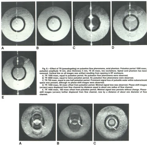
Fig. B.-Effect of TR (pseudogating) on pulsation flow phenomena, axial phantom. Pulsation period 1500 msec, pulsation amplitude 10 mm, slice thickness 5 mm, TE 25 msec, two excitations. Spinal cord phantom has been removed. Vertical line on all images was artifact resulting from opening in RF enclosure.
A, TR 1500 msec, equal to pulsation period. No pulsation flow phenomena were observed. B, TR 3000 msec, equal to twice pulsation period. No pulsation flow phenomena were observed.
C, TR 750 msec, equal to one-half pulsation period. Prominent signal loss of pulsatile water within subarachnoid space was present, although no phase-shift images were observed.
D, TR 1450 msec, 50 msec offset from pulsation period. Minimal signal loss was observed. Phase-shift images (arrows) were displaced from flow channel by distance equal to about one radius of flow channel.
E, TR 1400 msec, 100 msec offset from pulsation period. Minimal signal loss persists without change. Phase-shift images (arrows) further displaced from flow channel, now by a distance of about one diameter of flow channel.
B
c
Fig. 9.-Effect of pseudogating on CSF uniformity and conspicuity of CSF-thecal sac and CSF-spinal cord interfaces on axial phantom images. Phantom spinal cord was in place. Pulsation period 10BO msec, pulsation amplitude 10 mm, slice thickness 5 mm, TE 25 msec.
A, TR about 15 msec less than pulsation period. Convergence of multiple phase-shift images on subarachnoid space resulted in marked nonuniformity of signal both within (arrow) and adjacent to flow channel. CSF-thecal sac and CSF-spinal cord interfaces partially obscured.
B, TR about B msec less than two times pulsation period. Further convergence of multiple phase-shift images on subarachnoid space. Note higher signal-to-noise ratio that resulted from longer TR. Nonuniformity of signal within subarachnoid space was more pronounced (arrow). CSF-thecal sac and CSF-spinal cord interfaces almost completely obscured.
C, TR about equal to pulsation period. Almost complete convergence of phase-shift images was observed. Signal intensity within subarachnoid space was increased and nearly uniform. CSF-thecal sac (open arrow) and CSF-spinal cord (solid arrow) interfaces remain partly obscured because of imperfect pseudogating.
No consistent effect of slice spacing on either signal loss or phase-shift images was demonstrated in the axial plane whether slice spacing was constant, a percentage of slice thickness, or progressively increased using a constant slice
[image:7.612.100.494.439.585.2]314 RUBIN AND ENZMANN AJNR:8, March/April 1987
A
B
a larger field of view. Signal loss and phase-shift images were not affected by increasing image resolution from 128 to 256 phase-encoding increments.
Discussion
As shown in part 1 of this article [1], CSF pulsation flow phenomena encode physiologic information in normal spines, and their absence may signify pathologic conditions associ-ated with spinal block. Interpretation of these phenomena on clinical spine images is complex because their manifestations are influenced by both physiologic and imaging system param
-eters. A new spine phantom designed to simulate spinal CSF pulsation was investigated to determine the etiology of these phenomena and to demonstrate the significance of the nu-merous parameters. Understanding the theoretic basis for spinal CSF pulsation flow effects and the individual parame-ters influencing their expression not only facilitates recognition of these phenomena, but more importantly it offers control over them. These parameters can be manipulated to affect the outcome of imaging by either suppressing or enhancing pulsation flow phenomena, depending on the goal of imaging.
The rationale for CSF gating during clinical MR imaging of the spine to minimize these phenomena follows directly from understanding their etiology.
The pulsatile motion of spinal CSF represents a special case of pulsatile flow in general. CSF pulsation is unique because its oscillatory non propagating motion leads to actual reversal in direction of flow between cardiac systole and diastole. Although there are numerous reports dealing with continuous and pulsatile propagating flow in the MR literature
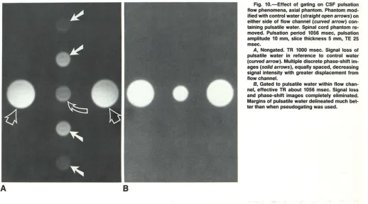
Fig. 10.-Effect of gating on CSF pulsation flow phenomena, axial phantom. Phantom mod-ified with control water (straight open arrows) on either side of flow channel (curved arrow) con-taining pulsatile water. Spinal cord phantom re-moved. Pulsation period 1056 msec, pulsation amplitude 10 mm, slice thickness 5 mm, TE 25 msec.
A, Nongated. TR 1000 msec. Signal loss of
pulsatile water in reference to control water
(curved arrow). Multiple discrete phase-shift
im-ages (solid arrows), equally spaced, decreasing signal intensity with greater displacement from flow channel.
B, Gated to pulsatile water within flow
chan-nel, effective TR about 1056 msec. Signal loss and phase-shift images completely eliminated. Margins of pulsatile water delineated much bet-ter than when pseudogating was used.
[2-30], the oscillatory nonpropagating motion characterizing spinal CSF has not yet been studied quantitatively. The mechanisms of spinal CSF pulsation in humans were de-scribed in part 1 of this article [1). Although bulk CSF circu-lation within the spinal subarachnoid space is also well rec-ognized, its contribution to spinal CSF motion during the course of MR imaging is insignificant because CSF formation is estimated at only about 0.33 mljmin, most of which circu-lates over the cerebral convexities to be absorbed by the arachnoid villi [31-34).
It has long been recognized that MR signal is influenced by proton motion [23-30] and that two mechanisms contribute to these flow phenomena: flow of protons through a sample or imaging plane (time-of-flight effects) and flow of protons within a nonuniform magnetic field (phase-shift effects) [2-4,
8-10). The manifestations of flow result from complex inter-actions between numerous factors related to flow hydrody
-namics (direction, velocity, acceleration, pulsatility, turbu-lence, lumen geometry, flow profile), and imaging system parameters (gating, pulse sequence, TR, TE, imaging plane, slice thickness, slice spacing, number of echoes, number of excitations, number of slices, field of view). In this article, we are concerned with gated and nongated spin-echo 2DFT imaging of spinal CSF pulsation that is characterized by oscillatory nonpropagating flow.
[image:8.612.54.572.86.374.2]exci-AJNR:8, MarchlAprii 1987 HARMONIC MODULATION OF PROTON MR PRECESSIONAL PHASE 315
tations and do not leave that volume between excitation and refocusing. Decreased signal intensity (signal loss) occurs at higher velocities when fully magnetized protons that entered the imaging volume between successive excitations leave the imaging volume between excitation and refocusing. This oc-curs because the selective refocusing pulses necessary for multislice imaging cannot rephase protons that leave the imaging volume. These flow effects depend on flow velocity,
flow direction in relation to the imaging plane, slice thickness,
TR, and TE. When flow is of constant velocity and perpendic-ular to an imaging plane, signal gain occurs at low velocities determined by the ratio of slice thickness to TR. Signal loss occurs at high velocities determined by the ratio of slice thickness to TE/2 for first-echo images and the ratio of slice thickness to 3TE/2 for second-echo images. The manifesta-tions of both low- and high-velocity time-of-flight effects are considerably more complex when imaging oscillatory non-propagating flow using multislice techniques. This occurs because an endless supply of fully magnetized protons is not available as with constant-velocity flow. Instead, a limited number of protons, which constantly reverse direction, are repeatedly excited as determined by TR, TE, slice thickness, slice spacing, pulsation amplitude, and pulsation period. How-ever, these time-of-flight effects are not the principal mecha-nism for the signal loss and phase-shift images characteristic of CSF oscillatory non propagating flow.
Phase-shift effects result in phase discrepancies between stationary and moving protons in a nonuniform magnetic field [2, 3, 8]. Magnetic gradients applied during the imaging process are usually the largest contributor to field nonuniform-ity responsible for these phase shifts. Most commercial ima-gers use linear gradients whose strength and duration are symmetric about refocusing pulses (balanced gradients). Un-der these conditions, phase shifts within stationary and flow-ing protons behave in predictable ways. While stationary protons within an imaging gradient change phase linearly with time, permiting refocusing at odd and even echoes, the phase shift associated with flowing protons within an imaging gra-dient is nonlinear with time and dependent on flow character-istics including direction, velocity, acceleration, and turbu-lence. For example, a quadratic phase shift with time occurs in the case of constant velocity flow. In the special case of constant velocity flow within an imaging plane, the quadratic phase shift results in incomplete rephasing of spins at odd echoes but complete rephasing at even echoes (even-echo rephasing) [10]. In the special case of constant acceleration within an imaging plane, incomplete rephasing of spins occurs at both odd and even echoes [2, 3].
During application of the imaging gradients, the differential precessional phase of a moving proton with respect to a stationary proton is described as d<l>n(t) = 'Y Pn(t) Gn dt, where d<l>n(t) = differential precessional phase of moving proton with respect to stationary proton; 'Y = magnetogyric ratio; Pn(t) =
time-dependent proton position vector projection on axis n; Gn
=
gradient field magnitude colinear with axis n; and n=
axis x, y, or z [2, 3, 23]. Assuming pure harmonic motion of the time-dependent proton-position vector, Pn(t) = An sin (wt),
where An = maximum amplitude of proton-position-vector
projection on axis nand w = angular frequency of pulsation.
Combining these equations, d<l>n(t) = 'Y An sin (wt) Gn dt. Therefore, in the case of spinal CSF pulsation in which oscillatory proton motion is approximately colinear with the z axis, the phase shift of moving protons with respect to stationary protons during a given interval should depend on pulsation amplitude (CSF oscillatory excursion), pulsation fre-quency (heart rate), and z-axis gradient magnitude. During axial imaging, the z-axis imaging gradient (in conjunction with RF bandwidth) determines slice thickness during application of 900 or 1800 RF pulses. The selection of thinner slices
requires the application of a larger z-axis gradient magnitude.
During sagittal imaging, the z-axis gradient performs fre-quency encoding during readout of the spin-echo signal. The other two imaging gradients (Gx, Gy) do not cause velocity-dependent phase changes in spinal CSF because proton motion is always normal to them. The fact that z-axis gradient magnitude varies with slice thickness during axial but not sagittal imaging explains the observed effects of slice thick-ness on pulsation flow phenomena on axial but not sagittal images.
Phase-shift effects are complex because their manifesta-tions depend on numerous spatial and temporal parameters related to both the imaging system and the flow characteris-tics. Spatial parameters include the hydrodynamic flow profile [2] and voxel dimensions. Temporal parameters include the pulsation period, TR, and number of spin-echo signals aver-aged before phase-encoding incrementation. To understand the effect of these parameters on precessional phase, it is necessary to distinguish between phase shift and phase
dispersion. Phase shift is used here to indicate a coherent
alteration in precessional phase of a group of moving protons relative to stationary protons whether they are spatially or temporally averaged. Phase dispersion is used to indicate an
incoherent alteration in precessional phase of a group of
moving protons relative to stationary protons whether they are spatially or temporally averaged.
Spatial phase shift is used here to refer to a coherent phase
shift at one pOint in time that results from the spatial averaging of spin-echo signals from a group of protons whose direction,
velocity, and acceleration within an imaging voxel are equal.
Temporal phase shift refers to a time-varying spatial phase
shift that results from changes in proton direction, velocity,
and/or acceleration between successive nonaveraged exci-tations. Spatial phase dispersion refers to an incoherent phase shift at one point in time resulting from the spatial averaging of spin-echo signals from a group of protons whose hydro-dynamic flow profile exhibits a spatial distribution of direction,
velocity, and/or acceleration within an imaging voxel. This commonly occurs at flowing fluid interfaces where shear forces establish a velocity gradient within the boundary layer [35, 36]. During imaging of pulsatile CSF, various combina-tions of spatial phase shift, temporal phase shift, and spatial phase dispersion may be observed in different regions of the subarachnoid space.
316 RUBIN ANO ENZMANN AJNR:8. March/April 1987
period (gating and pseudogating), aliasing simulates constant velocity flow because CSF velocity and direction are constant each time they are sampled, leading to spatial phase shift and spatial phase dispersion. The manifestations of spatial phase dispersion that are unmasked under these circumstances are considered elsewhere [35]. When TR is not an integral multi-ple of the pulsation period, CSF direction and velocity are different during successive excitations, leading to manifesta-tions of temporal phase shift. Spatial phase dispersion is masked by temporal phase shift under these circumstances.
Temporal phase-shift effects are directly responsible for CSF pulsation flow phenomena (signal loss and phase-shift im-ages), although they depend on application of the 20FT for their expression.
In general, 20FT (spin-warp) imaging relies on the fact that temporal frequency encoding corresponds to the first spatial Fourier variable (Kx[t]), whereas successive phase encoding of spin-echo signals corresponds to the second spatial Fourier variable (Ky[<I>]). Image reconstruction is performed by suc-cessive applications of the discrete Fourier transform to the first and then second spatial Fourier variables. Because precessional phase is encoded as the second spatial Fourier variable, artifacts related to phase shift are always encoded along this axis of the spatial Fourier plane.
Temporal phase shift represents a harmonic modulation of proton precessional phase, which occurs during imaging of oscillatory non propagating flow when TR is not an integral multiple of the pulsation period. This influences the outcome of the 20FT according to the Fourier frequency shift theorem (Fig. 11). This theorem defines the frequency shift from baseband (appearance of sidebands) that occurs from mod-ulation in the time domain [37, 38]. In the case of 20FT imaging, because modulation affects the second spatial Four-ier variable (Ky[ <1>]), the frequency shift is apparent as a spatial displacement along the phase-encoding axis on MR images. In the case of CSF pulsation flow phenomena, phase-shift images correspond to sidebands, whereas signal loss within pulsatile CSF occurs because of frequency shift of signal from the baseband. The displacement of phase-shift images from the pulsating CSF is a function of the frequency difference between the heart rate and TR. The intensity of phase-shift images occurs at the expense of pulsating CSF signal and is dependent on pulsation amplitude. Gating and pseudogating prevent temporal phase shift (harmonic modulation of proton precessional phase on successive excitations) so frequency shift of signal from the baseband does not occur.
One important difference between axial and sagittal CSF pulsation flow phenomena is the incomplete even-echo re-phasing observed on sagittal second-echo images. This oc-curs because the time required for spin-echo imaging (exci-tation-refocusing-readout) is usually short relative to the CSF pulsation period. Even though acceleration and deceleration characterize spinal CSF motion, at any time this motion is approximated by constant velocity flow provided that the TE is not prohibitively long. The phase shift of protons at the time of the first echo depends on their velocities while the readout gradient is on. Changing proton velocity between successive
hltl Hili
A
B yltl = cosl21Tlotl YIII
©>
____ ~ __ +_-L----~c
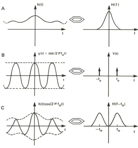
hlt)cosI21Tlot)Fig. 11.-Fourier transform frequency-shift theorem. Fourier transform pairs: time domain on left and frequency domain on right.
A, Fourier transform H(f) of real function hIt) is frequency distribution. Central peak is known as baseband frequency.
B, Fourier transform Y(f) of cosine function y(t) is single frequency pair (f, -f) determined by frequency of cosine function.
C, Process of multiplying two harmonic time-domain functions is com-monly known as modulation, and result of this on Fourier transform is frequency shift from baseband frequency resulting in appearance of sidebands on each side of baseband. In this example, product of time domain functions hIt) and y(t) is shown on left; corresponding Fourier transform is on right. (Modified from [37].)
excitations causes a temporal phase shift that is responsible for signal loss and phase-shift images on first-echo images.
However, because of the quadratic phase relationship gov-erning constant velocity flow, application of the readout gra-dient for the second echo results in rephasing of protons on successive eXCitations, irrespective of their different first-echo phases. This rephasing is not perfect because the CSF flow only approximates constant velocity flow. The result is a relatively constant phase shift on second echoes that sub-stantially reduces temporal phase shift, even though velocity varies from one excitation to the next. The necessary approx
-imation of constant velocity flow by pulsatile CSF for even-echo rephasing explains the effect of TE on CSF pulsation flow phenomena. With increasing TE, the approximation of constant velocity flow is reduced because imaging time is prolonged in relation to the CSF pulsation period. The signif-icance of these observations pertaining to the use of asym-metric echo pulse sequences during spinal imaging will be described elsewhere [35, 36].
[image:10.612.318.560.88.347.2]AJNR:8, March/April 1987 HARMONIC MODULATION OF PROTON MR PRECESSIONAL PHASE 317
spatial mismapping of CSF signal intensity because it is descriptive of both its etiology and manifestations on MR images: The fundamental basis for the phenomenon is related to precessional phase shift, whereas the artifact retains sig-nificant image detail involving subarachnoid anatomy. The "anatomic information" displayed by phase-shift images de-pends on uniformly periodic motion. Although varying- fre-quency periodic motion within the spinal CSF is capable of spatially mismapping signal by the mechanisms just de-scribed, the outcome is different. Variations in the frequency of motion result in variable frequency shifts after 20FT that are apparent on MR images as variable phase shifts. The spatially mismapped signal then appears randomly distributed along the phase-encoding axis of the image without the morphologic features of the flow channel.
Although a hydrodynamic model such as the spine phantom cannot achieve complete simulation of a complex in vivo system, correlative findings between clinical examinations and phantom images suggest that it is valid to draw conclusions regarding MR imaging of spinal CSF pulsation from the phan-tom data. It must be recognized, however, that a number of physiologic parameters are not modeled in the phantom, and under some circumstances they would alter the manifesta-tions of CSF pulsation during clinical imaging. Variations in pulsation period in humans secondary to arrhythmias would alter the appearance of phase-shift images as already de-scribed, although this should be compensated for at least in part by CSF gating, depending on the type of arrhythmia. Variations in pulsation amplitude that occur during cough, hyperventilation, and Val salva may also influence the appear-ance of the pulsation flow phenomena. Although in the phan-tom spine it was possible to perform direct CSF gating, in humans this is not possible. However, the constant phase relationship between cardiac activity and CSF motion permits adaptation of indirect monitoring devices (ECG, photopleth -ysmograph, or Doppler) to achieve identical results, as we have shown elsewhere [36].
Manipulation of imaging parameters during clinical ex ami-nations to alter the manifestations of pulsatile flow should prove very useful in several circumstances. When anatomic detail and optimum SIN ratio is necessary to demonstrate the CSF-thecal sac and CSF-spinal cord interfaces on long TR pulse sequences, minimizing signal loss and phase-shift im-ages may be accomplished using CSF gating. When physio-logic information such as CSF pulsation amplitude would be useful to evaluate the degree of spinal block, maximizing the pulsation flow phenomena may be accomplished by selecting a TR that is not an integral multiple of the heart rate and using thin sections during axial imaging. The potential for noninva-sive quantitation of CSF pulsation amplitude with nongated MR imaging is illustrated in this article, although additional work is necessary to calibrate the measurements in clinical examinations and to establish their clinical significance. Ap-plication of these methods to clinical imaging may provide more anatomic, pathologic, and physiologic information from MR imaging of the spine than is currently available from any noninvasive method.
ACKNOWLEDGMENTS
We thank Alan Wright for his valuable assistance in implementing gating on the GE Signa system, and Scott Rand and John Pauley for their helpful comments on the manuscript.
REFERENCES
1. Rubin JB, Enzmann DR. Imaging of spinal CSF pulsation by 20FT MR:
significance during clinical imaging. AJNR 1987;8:297-306
2. von Schulthess GK, Higgins CB. Blood flow imaging with MR: spin-phase
phenomena. Radiology 1985; 157: 687-695
3. von Schult hess GK, Fisher M, Crooks LE, Higgins CB. Gated MR imaging
of the heart: intracardiac signals in patients and healthy subjects. Radiology
1985;156: 125-132
4. Bradley WG, Waluch V. Blood flow: magnetic resonance imaging. Radiol
-ogy 1985;154:443-450
5. Moran PR, Moran RA, Karstaedt N. Verification and evaluation of internal flow and motion. True magnetic resonance imaging by the phase gradient modulation method. Radiology 1985;154:433-441
6. Wehrli FW, Shimakawa A, McFall JR, Axel L, Perman W. MR imaging of
venous and arterial flow by a selective saturation recovery spin-echo
method. J Comput Assist Tomogr 1985;9:537-545
7. O'Donnell M. NMR blood flow imaging using multiecho phase contrast sequences. Med Phys 1985;12:59-64
8. Axel L. Blood flow eHects in magnetic resonance imaging. AJR
1984;143: 1157-1166
9. Bradley WG, Waluch V, Ka-Siu L, Fernandez EJ, Spalter C. The appear -ance of rapidly flowing blood on magnetic resonance images. AJR
1984;143: 1167-1174
10. Waluch V, Bradley WG. NMR even echo rephasing in slow laminar flow. J
Comput Assist Tomogr 1984;8:594-598
11. Bryant OJ, Payne JA, Firmin ON, Longmore DB. Measurement of flow with
NMR imaging using a gradient pulse and phase diHerence technique. J Comput Assist Tomogr 1984;8:588-593
12. van Dijk P. Direct cardiac NMR imaging of heart wall and blood flow velocity. J Comput Assist Tomogr 1984;8:429-436
13. Feinberg DA, Crooks LE, Hoenninger J, Arakawa M, Watts J. Pulsatile blood velocity in human arteries displayed by magnetic resonance imaging.
Radiology 1984;153:177-180
14. Schultz CL, Alfidi RJ, Nelson AD, Kopiwoda SY, Clampitt ME. The eHect
of motion on tWO-dimensional fourier transformation magnetic resonance
images. Radiology 1984;152: 117-121
15. George CR, Jacobs G, Macintyre WJ, et al. Magnetic resonance signal
intensity patterns obtained from continuous and pulsatile flow models.
Radiology 1984;151 :421-428
16. Wehrli FW, Mac Fall JR, Axel L, Shutts 0, Glover GH, Herfkens RJ.
Approaches to in-plane and out-of-plane flow imaging. Noninvasive Med
Imag 1984;1 :127-136
17. Mills CM, Brant-Zawadzki M, Crooks LE, et al. Nuclear magnetic r
eso-nance: principles of blood flow imaging. AJNR 1983;4: 1161-1166
18. Singer JR. Crooks LE. Nuclear magnetic resonance blood flow measure-ments in the human brain. Science 1983;221 :654-656
19. Crooks LE, Mills CM, Davis PL, et al. Visualization of cerebral and vascular abnormalities by NMR imaging. The eHects of imaging parameters on contrast. Radiology 1982;144:843-852
20. Moran PRo A flow velocity zeugmatographic interlace for NMR imaging in
humans. Magnetic Resonance Imag 1982;1 :197-203
21. Grant JP, Back C. NMR rheotomography: feasibility and clinical potential.
Med Phys 1982;9:188-193
22. Battocletti JH, Halback RE, Salles-Cunha SX, Sances A Jr. The NMR blood flowmeter-theory and history. Med Phys 1981;8:435-443, 445-451,452-458
23. Singer JR. NMR diHusion and flow measurements and an introduction to spin phase graphing. J Phys E Sci Instrum 1978;11 :281-291
24. Jones OW, Child TF. NMR in flowing systems. In: Waugh JS, ed. Advances
318 RUBIN AND ENZMANN AJNR:8, March/April 1987
1971;42:938-940
26. Morse ~C, Singer JR. Blood velocity measurements in intact sUbjects.
Science 1970;170:440-441
27. Hahn EL. Detection of sea water motion by nuclear precession. J Geophys
Res 1960;65:776-777
28. Singer JR. Blood-flow rates by NMR measurements. Science
1959;130: 1652-1653
29. Carr HY, Purcell EM. Effects of diffusion on free precession in nuclear
magnetic resonance experiments. Phys Rev 1954;94:630-638
30. Suryan G. Nuclear resonance in flowing liquids. Proc Indian Acad Sci
1951;33: 1 07-111
31. McComb JG. Recent research into the nature of cerebrospinal fluid
for-mation and absorbtion. J Neurosurg 1983;59:369-383
32. Cutler RWP, Page L, Galicich J, et al. Formation and absorbtion of
cerebrospinal fluid in man. Brain 1968;91 :707-720
33. Lorenzo AV, Page LK, Watters GV. Relationship between cerebrospinal
fluid formation, absorbtion, and pressure in human hydrocephalus. Brain
1970;93: 679-692
34. Rubin RC, Henerson ES, Om maya AK, Walker MD, Rail DP. The production
of cerebrospinal fluid in man and its modification by acetazolamide. J
Neurosurg 1966;25:430-436
35. Rubin JB, Enzmann DR. Optimizing conventional MR spine imaging. Ra
-diology 1987 (in press)
36. Rubin JB, Enzmann DR, Wright A. CSF gated spine MRI: theory and clinical implementation. Radiology 1987 (in press)
37. Bracewell RN. The Fourier transform and its applications. New York:
McGraw Hill, 1978