THE EFFECTS OF WING ROTATION ON UNSTEADY
AERODYNAMIC PERFORMANCE AT LOW REYNOLDS
NUMBERS
MICHAEL H. DICKINSON
Department of Organismal Biology and Anatomy, The University of Chicago, 1025 East 57th Street, Chicago, IL 60637, USA
Accepted 18 March 1994
Summary
The downstroke-to-upstroke transition of many insects is characterized by rapid wing rotation. The aerodynamic consequences of these rapid changes in angle of attack have been investigated using a mechanical model dynamically scaled to the Reynolds number appropriate for the flight of small insects such as Drosophila. Several kinematic parameters of the wing flip were examined, including the speed and axis of rotation, as well as the duration and angle of attack during the wing stroke preceding rotation. Alteration of these kinematic parameters altered force generation during the subsequent stroke in a variety of ways.
1. When the rotational axis was close to the trailing edge, the model wing could capture vorticity generated during rotation and greatly increase aerodynamic performance. This vortex capture was most clearly manifested by the generation of lift at an angle of attack of 0 ˚. Lift at a 0 ˚ angle of attack was also generated following rotation about the leading edge, but only if the downstroke angle was large enough to generate a von Karman street. The lift may be due to an alteration in the effective angle of attack caused by the inter-vortex stream in the downstroke wake.
2. The maximum lift attained (over all angles of attack) was substantially elevated if the wing translated backwards through a wake generated by the previous stroke. Transient lift coefficient values of nearly 4 were obtained when the wing translated back through a von Karman street generated at a 76.5 ˚ angle of attack. This effect might also be explained by the influence of the inter-vortex stream, which contributes a small component to fluid velocity in the direction of translation.
3. The growth of lift with angle of attack was significantly elevated following a 7.5 chord stroke with a 76.5 ˚ angle of attack, although it was relatively constant under all other kinematic conditions.
4. The results also indicate the discrepancies between transient and time-averaged measures of performance that arise when unsteady mechanisms are responsible for force generation. Although the influence of wing rotation was strong during the first few chords of translation, averaging the performance over as little as 6.5 chords of motion greatly attenuated the effects of rotation.
5. Together, these modeling results suggest that the unsteady mechanisms generated by simple wing flips could provide an important source for the production of aerodynamic
forces in insect flight. Furthermore, the extreme sensitivity to small variations in almost all kinematic parameters could provide a foundation for understanding the aerodynamic mechanisms underlying active flight control.
Introduction
Unlike the lift-generating surfaces of planes and helicopters, the wings of animals must frequently change direction. The wing motion of many animals consists of alternating upstrokes and downstrokes, each with an appropriate angle of attack. Between these two half-strokes, the wing is rotated in apparent preparation for the next cycle. These wing rotations are most extreme in animals that utilize a roughly horizontal stroke plane (Ellington, 1984a), including such sophisticated aerialists such as flies, bees and hummingbirds. During stroke reversals, the rotational velocity of the wing can be large while the translational velocity is low. As a consequence, traditional ‘quasi-steady-state’ flight theory put little emphasis on the potential aerodynamic contribution of stroke reversal. This view was partly corrected by Ellington (1984c), who recognized that wing rotation is itself a source of circulation that will be especially large during supinations. However, even this more accurate quasi-steady model probably underestimates the importance of wing rotation.
During the last decade, the assumptions of the quasi-steady-state theory have been challenged on both theoretical and experimental grounds (see Ellington, 1984b; Spedding, 1992, for reviews). As steady-state approaches are put to rest, interest within the wing-beat cycle has shifted from force production during the two wing strokes themselves to what happens during the stroke reversals. The first well-demonstrated unsteady mechanism, the ‘clap and fling’, occurs during the upstroke-to-downstroke transition (Weis-Fogh, 1973; Lighthill, 1973; Ellington, 1975; Maxworthy, 1979; Spedding and Maxworthy, 1986). In flies, whose kinematics have been described in great detail (Nachtigall, 1966; Ennos, 1989; Zanker, 1990), the ventral stroke reversal is extremely rapid, in contrast to a more gradual pronation of the wing during the dorsal reversal. Zanker (1990) estimated that angular velocities exceed 105degrees s21during the ventral flip in Drosophila, although this value is certainly an underestimate due to temporal averaging in his visualization technique. Recent behavioral studies (Dickinson et al. 1993) indicate that Drosophila actively modulates the relative timing of the ventral flip on the two wings during turning maneuvers. Several unsteady mechanisms have been proposed for rapid supinations (Nachtigall, 1979; Ellington, 1984a; Ennos, 1989), but their rapidity makes direct visualization of flow patterns difficult, even with high-speed cinematography. This paper attempts to circumvent this limitation by using dynamically scaled model wings to study the aerodynamic importance of wing rotations. A similar approach was taken by Savage
et al. (1979) in their analysis of dragonfly hovering. In the present study, rather than
supination during the ventral flip, and investigates how kinematic modifications of the flip might provide a means of regulating aerodynamic forces for steering.
In the first paper of this series, Dickinson and Götz (1993) measured the lift and drag forces on a model Drosophila wing started impulsively from rest. At angles of attack greater than about 15 ˚, lift on the wings was greatly augmented by the presence of a leading-edge vortex that stayed attached to the wing for the first few chord lengths of motion. In the experiments presented here, I use exactly the same paradigm, except that the motion of the wing model consists of two translations of opposite direction separated by a rapid rotation. Instantaneous measurements of flight forces in Drosophila indicate that a large force peak is generated immediately following the ventral flip, during the first half of the upstroke (Zanker and Götz, 1990; K. Götz, personal communication). Consequently, the experiments were designed to measure the effect of the first translation and stroke reversal on the generation of forces during the subsequent translation. The potential number of variables in such a system is enormous, so the investigation has been limited to four important parameters of stroke reversal that could potentially influence force generation during the subsequent stroke: (1) the position of the rotational axis, (2) the speed of rotation, (3) the angle of attack of the preceding stroke, and (4) the length of the preceding stroke.
Materials and methods Experimental apparatus
The basic techniques and analysis used in this study have been extensively described in a previous paper (Dickinson and Götz, 1993) and are only briefly outlined here. All experiments employed a 1 mm thick aluminum wing section 15 cm in length and with a 5 cm chord. The studies were carried out in a 200 l aquarium filled with 54 % sucrose solution, with a measured kinematic viscosity of 0.25 cm2s21(0.25 stokes). The wing model could be translated and rotated through perpendicular axes by the action of two computer-operated stepper motors. Forces parallel and normal to the wing surface were measured by a two-dimensional force transducer. Lift and drag forces, defined with respect to the direction of motion, were reconstructed trigonometrically. The sectional lift and drag coefficients were calculated according to standard methods, except that they are represented as functions of time.
Experimental procedure
velocities during the ventral flip make v more difficult to estimate given the temporal resolution of current imaging techniques. Zanker (1990) gave a lower-limit estimate of 105degrees s21, but the wing can undergo a 90 ˚ rotation within a 200ms temporal window seen in stroboscopic analysis (F.-O. Lehmann, personal communication). Given these values, I estimated the angular velocity during the flip to be in the range 33105 to 53105degrees s21, which yields a range for kof about 3.5–6. In most experiments, I used a kvalue of 4.5, which required a rotational velocity of 625 degrees s21. Obviously, this value can only be considered to be a rough estimate, and one set of experiments explicitly examines the effect of rotational velocity on unsteady force production. The acceleration of the wing model to final translational and rotational velocities required 80 and 14 ms, respectively, with an identical time course during decelerations. The motion controller was configured such that rotation began immediately following the termination of the downstroke and the upstroke started immediately upon termination of rotation. The only source of delay between the three stroke phases was the single line processing time of an IBM 386 computer running BASIC, which was small compared with the acceleration times given above. This temporal segregation of translation and rotation was extremely convenient because it allowed separation of the various inertial force transients that result whenever the wing is accelerated. By beginning translation after rotation had been completed, it was possible to measure unambiguously the effect of rotation on the production of aerodynamic forces, uncontaminated by the large inertial transients. In addition, measured lift and drag were due only to translation, since the angular velocity of the wing was always zero during the upstroke. Of course, translation and rotation are not so neatly separated during the stroke reversal of a real fly. However, it was not my intent to mimic precisely normal flight kinematics, but rather to explore more broadly the potential contributions of stroke reversal to force production during the subsequent translation.
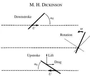
Lift
Drag ad
au
U v
Downstroke
Upstroke
Rotation
U
The direction of wing rotation between the downstroke and upstroke was always such that the leading edge moved in the direction of upstroke translation (Fig. 1). This corresponds to supination that occurs on actual fly wings. The angular motion during the rotation phase was thus equal to 180 ˚2(ad+au), where adand auare the angles of attack during the downstroke and upstroke, respectively. The force measurements from four runs with identical parameters were averaged for each trial. Each experimental set consisted of 23 trials, in which the angle of attack during either the downstroke or the upstroke was varied in 4.5 ˚ steps from 29 ˚ to 90 ˚. In addition, each complete set of 23 angles of attack was repeated for three different configurations: leading edge, half chord and trailing edge rotation. These configurations were accomplished by attaching the sting descending from the force transducer to positions 1.0, 2.5 and 4.0 cm, respectively, from the leading edge of the profile, corresponding to the 0.2, 0.5 and 0.8 chord points.
Comparison of transient and steady-state aerodynamic performance
In the first paper of this series (Dickinson and Götz, 1993), the transient and steady-state performances of the model wing were compared by examining the instantaneous values of the lift coefficient CL and the drag coefficient CDmeasured at 2 and 7 chord lengths of translation. In the present study, however, variations in the time course of vortex generation and shedding are more extreme, and instantaneous values could give a misleading representation of the performance differences between experimental conditions. For these reasons, I have employed a slightly different method for comparing the early and ‘steady-state’ aerodynamic performance throughout this paper. The force coefficients are integrated over two different translational distances: from 1 to 3 and from 1 to 7.5 chord lengths of travel. For comparison, the values have been normalized to the number of chords traveled and are equivalent to the mean values of CLand CDover the integration interval. For convenience, I refer to the values integrated from 1 to 3 chords of travel as transient values and those integrated from 1 to 7.5 chord lengths as average values. In both cases, the 1 chord point was chosen for the start of integration so that the values would not be contaminated by inertial forces at the start of translation.
Flow visualization
During most experiments, the pattern of fluid flow was visualized with aluminum particles and recorded from below on video tape (Dickinson and Götz, 1993). The flow of fluid during wing rotation was very fast relative to the temporal resolution of the video system. For this reason, a few additional visualizations were made at half the Reynolds number of the force measurements (Re=115), but using the same reduced frequency value. Although some minor differences were apparent between the flows visualized under these two regimes, the basic pattern of flow was similar.
Results Axis of rotation
(concerning rotational speed), the angle of attack during the downstroke is zero, so that the force production during the upstroke is not complicated by flows generated by the previous stroke. For comparison, the top traces in Fig. 2 show CLand CDtrajectories for
4
2
0
−2 d
CL CD
4
2
0
−2 +45 °
Lift Drag
Pure translation
0.2 chord rotation
0.5 chord rotation
0.8 chord rotation
−9 °
+45 °
−9 °
+45 °
−9 °
+45 °
−9 °
+45 °
−9 °
+45 °
−9 °
+45 °
−9 °
+45 °
−9 °
0
r u u
2 4 6 8
Chord lengths
d
0 r
2 4 6 8
Chord lengths
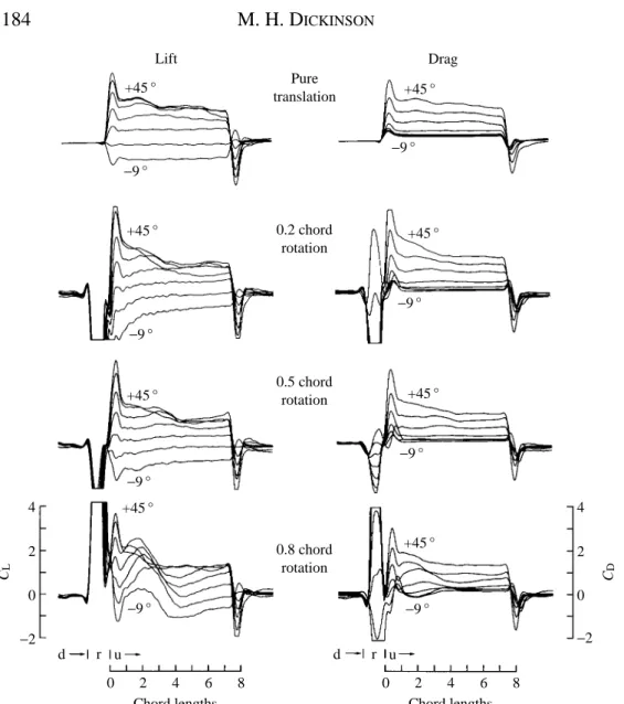
an impulsive start to the same translational velocity, but in the absence of a downstroke and rotation (hereafter called pure translation). The large excursions near the beginning of the lower three sets of traces result from the inertial and aerodynamic forces that occur during rotation. The linear acceleration of the model then causes a second smaller positive transient in both lift and drag that is also present in pure translation.
The performance of the model wing after a flip deviates most from that of the pure translational case when the axis of rotation is near the trailing edge of the wing (0.8 chord rotational axis). These kinematic conditions produce a large broad force transient that acts on the wing for the first three chord lengths of travel. It is important to note that this positive transient is present even when the upstroke angle of attack auis zero or less. This observation illustrates a potentially important role for wing rotation in insects. The rotation of the wing preceding translation can act to generate a vortex that is subsequently captured by the upper surface of the wing at the start of translation. This vortex produces lift over the first several chord lengths of travel, even at angles of attack below the threshold for leading edge separation in pure translation.
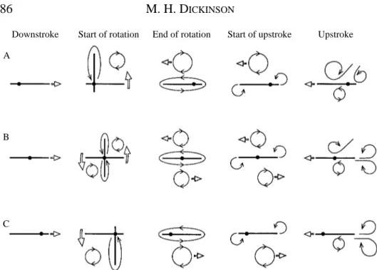
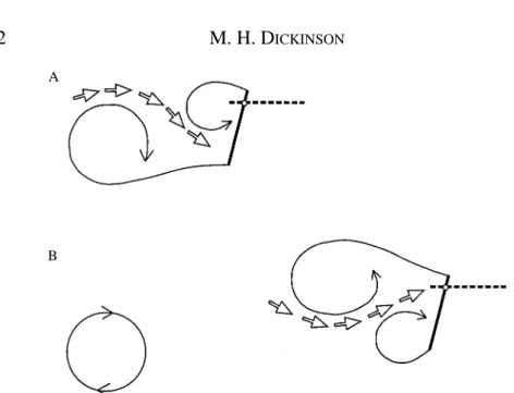
What is the precise source of the vortex responsible for the forces transients? Why is the capture so strongly dependent on the axis of rotation? A cartoon illustrating the pattern of vortex development reconstructed from video segments during a wing flip is shown in Fig. 3. In this simple case, no circulation is developed during the downstroke since the angle of attack is zero, although the pattern is similar with downstroke angles up to 13.5 ˚, the point at which vortex shedding commences. Two vortices form at the onset of rotation. The first is a bound vortex moving with the wing in the direction of rotation. The second is a free vortex that is shed from the wing edge undergoing the most shear during rotation. As required by Kelvin’s law, this vortex possesses a strength equal and opposite to that of the bound vortex on the wing and is analogous with a starting vortex in translational motion. Because of this symmetry, I will refer to this structure as the mirror
vortex. A similar pattern was visualized by Savage et al. (1979) at a Reynolds number of
edges of the wing. At the completion of rotation, the two bound vortices are shed, leaving a system of four vortices at the onset of translation. One mirror vortex resides above the wing and could potentially contribute to lift augmentation, although its strength must be roughly half of that produced by rotation about the 0.8 chord point.
The pattern of flows described above correlates well with the force trajectories. With the rotational axis at the 0.2 chord point, in which the mirror vortex forms under the wing, the lift is transiently negative at upstroke angles of 4.5 ˚ and below and appears to be sluggish compared with the pure translation case. The performance in the case of rotation about the 0.5 chord point is a little better, but does not show the strong vortex lift seen with rotation about the 0.8 chord point.
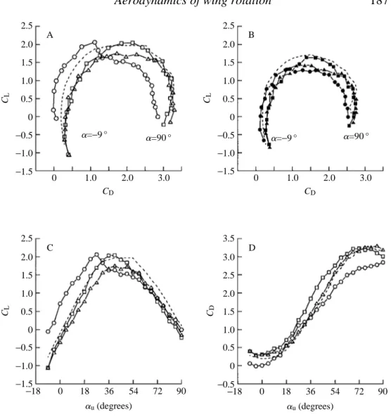
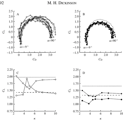
The changes in the development of the aerodynamic force due to the position of the rotational axis are shown in conventional polar diagrams in Fig. 4. The augmentation of transient performance with a 0.8 chord axis of rotation is quite remarkable: the drag is actually negative at 24.5 and 0 ˚ angles of attack (Figs 2, 4A,D). The presence of
B
C A
Downstroke Start of rotation End of rotation Start of upstroke Upstroke
2.5 2.0 1.5 1.0 0.5 0 −0.5 −1.0 −1.5 CL B C D A
a=−9 ° a=90 °
0 1.0 2.0 3.0
CD 2.5 2.0 1.5 1.0 0.5 0 −0.5 −1.0 −1.5 CL
a=−9 ° a=90 °
0 1.0 2.0 3.0
CD 2.5 2.0 1.5 1.0 0.5 0 −0.5 −1.0 −1.5 CL 3.5 3.0 2.5 2.0 1.5 1.0 0.5 0 −0.5 CD 0
−18 18 36 54 72 90 au(degrees)
0
−18 18 36 54 72 90 au(degrees)
negative drag could indicate that the total force vector, the resultant of both lift and drag, is oriented roughly normal to the surface of the profile, as expected by the fulfilment of the Kutta condition on both the leading and trailing edges of the wing. At negative angles of attack, the total force vector must tilt slightly forward, resulting in a negative drag that is temporarily larger than the contribution due to skin friction. Following rotation about the 0.8 chord axis, the mirror vortex is thrown forwards in the direction of the upstroke. The change in fluid momentum in this direction would be manifest as a negative drag force during translation. In contrast, rotation about the 0.2 chord axis should increase drag, since the vortex is thrown backwards against the direction of upstroke translation.
Vortex capture is not without its costs (Fig. 4A,C). Following rotation about the 0.8 chord point, transient lift falls quite rapidly at angles of attack above 22.5 ˚, while it continues to grow with increasing angle of attack for the two more anterior rotational axes. In pure translation, a leading edge vortex begins to develops at angles of attack greater than 13.5 ˚. With the addition of wing rotation preceding translation, the vorticity generated by translation appears to sum linearly with that already present due to vortex capture, indicated by an upward shift in the curves of Fig. 4C. However, as is evident from the loss of lift at higher angles of attack, the leading edge vortex cannot grow without bounds and becomes unstable as more vorticity is added during translation. The maximum lifts attained after rotation about the 0.8 and 0.2 chord axes are quite similar (Fig. 4C), suggesting that there is a limit to the size of a leading edge vortex for a given upstroke angle and Reynolds number. This result is expected from the limitations on the accumulation of vorticity in dynamic stall (McCrosky, 1982; Wu et al. 1991). However, despite the appearance of simple addition, the actual interaction between vorticity generated during rotation and translation must be much more complex, as indicated by comparing the lift trajectories in Fig. 2. At high upstroke angles, the captured vortex is rapidly shed, and the subsequent von Karman pattern appears to be ‘re-set’ slightly, relative to the pure translation case. This indicates that both the magnitude and the dynamics of shedding during translation are affected by the additional vorticity.
generation elicited by subtle changes in the rotation kinematics become less noticeable as values are averaged over periods longer and longer from the onset of translation.
Speed of rotation
Fig. 5 shows lift and drag trajectories at several angles of attack for five different rotational velocities, expressed as reduced frequency values, k. The values were chosen roughly to bracket the estimate made for Drosophila during the ventral flip. The peak values in CLare small at low rotational speeds (k=2.5), increase at intermediate speeds (k=4.5) and then decrease again at higher kvalues. In addition, the time to peak and the duration of the lift transients increase with increasing flip speed. These trends probably result from two characteristics of vortex development. First, since the strength of bound vorticity on the wing must increase with increasing rotational velocity, so must the strength of the mirror vortex. Second, the velocity of rotation also influences the motion of the mirror vortex center, which determines how close it comes to the upper surface of the wing and how long it stays there. This, in turn, will determine the extent to which the mirror vortex influences lift production. These complex effects, brought about by changes in rotational speed, are manifest in the variation among the polar diagrams of the transient force coefficients (Fig. 6A). There is a local maximum in the transient lift values at a reduced frequency of 4.5, where CLreaches a value about 0.5 higher than that attained in pure translation at the same angle of attack (Fig. 6C, dashed line). Fig. 6C also illustrates the cost of vortex capture at higher angles of attack. At 45 ˚ there is a minimum in transient CL at intermediate k values, which drops well below values attained in pure translation (dotted line). This loss of lift probably results from the influence of added vorticity on the dynamics of von Karman shedding. With the addition of extra vorticity, the initial leading edge vortex may be shed too quickly to offer much aerodynamic advantage.
Despite the clear differences in the time course of the force coefficients (Fig. 5), changes in rotational speed have little effect on the average performance of the model wing over the full translational distance (Fig. 6B). The average values of CLat 22.5 and 45 ˚ angles of attack are not as strongly dependent on reduced frequency, and in all cases the values are lower than those attained in the absence of rotation (Fig. 6D).
Downstroke angle of attack
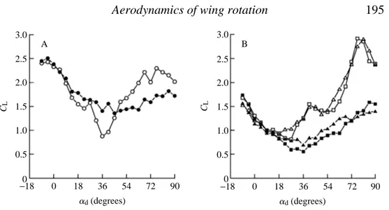
made, was constant at 22.5 ˚. When the downstroke angle of attack is low, the duration of the downstroke makes little difference to the performance of the model wing. However, the lift trajectories following long and short downstrokes begin to diverge at advalues greater than 13.5 ˚, precisely the angle where vortex shedding begins to develop in the case of pure translation (Fig. 8A,B). This suggests that the strength and orientation of downstroke vortices at the time of wing rotation may be important in determining the
4
2
0
CL CD
4
2
0 +45 °
Lift Drag
Reduced frequency parameter
−9 °
+45 °
−9 °
+45 °
−9 °
+45 °
−9 °
+45 °
−9 °
+45 °
−9 °
+45 °
−9 °
+45 °
−9 °
+45 °
−9 °
+45 °
−9 °
0 2 4 6 8
Chord lengths
0 10
6.25
4.5
3.25
2.5
2 4 6 8
time course and strength of vortex production during the subsequent stroke. As with all other experiments, the effect of downstroke angle on upstroke lift also depends upon the axis of wing rotation. Following rotation about the 0.8 chord point (Fig. 8A), the highest
CLvalues following a 7.5 chord downstroke occur at advalues near 0 ˚, reach a minimum near 36 ˚ and rise again with as adapproaches 90 ˚. Consistent with the previous results (Figs 2, 4), there is less difference between the transient values of CLfor wing rotations about the 0.2 and 0.5 chord axes (Fig. 8B). In both cases, transient performance declines until about 18 ˚, and then grows with increasing angle of attack until reaching a maximum of about 3 near 72 ˚. For all three rotational axes, the influence of downstroke angle on the lift generated at a 22.5 ˚ angle of attack is much less when the downstroke is only two chords in duration.
The effects of upstroke angle with a large downstroke angle
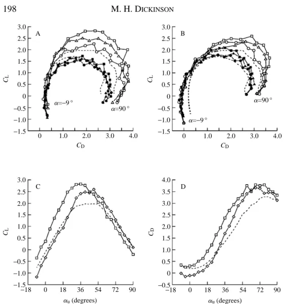
The results of the previous section demonstrated that downstroke angle could have an enormous effect on force production during the following upstroke. To explore this interaction further, auwas once again varied from 29 to 90 ˚, while holding adconstant at 76.5 ˚. This downstroke angle was chosen because it generated large values of lift in the previous experiments (Fig. 8). As before, upstroke performance was examined under six conditions: three axes of wing rotations at two downstroke distances. As seen in the individual force trajectories of Fig. 9 and the polar diagrams of Fig. 10, these conditions produced the greatest lift augmentation measured in the entire study. Instantaneous lift coefficients approached values of 4, or about twice those measured in pure translation. The greatest increase in transient lift occurs when the wing rotates about the 0.2 chord axis, and the increase was least following rotation about the 0.8 chord point. This order of performance is exactly opposite to that measured when adwas 0 ˚ (Fig. 4).
Although the flow patterns during a flip from a large downstroke angle were more complex due to the vortex street, the basic sequences of vortex generation and shedding were similar to those described for a 0 ˚ downstroke. Following rotation about the 0.8 chord axis, a mirror vortex forms above the wing and must contribute to the large transient increase in lift (Fig. 11, right-hand frames). A more puzzling result, however, is that the lift transients following rotation about the 0.2 chord axis were actually larger, despite the fact that the mirror vortex forms, as expected, below the wing (Fig. 11, left-hand frames). One conspicuous feature of the visualizations following rotation about the 0.2 chord axis was a substantial ‘backwash’ of fluid that intercepted the wing at a large effective angle of attack before the onset of translation. This flow originated from the region between the leading and trailing edge vortices of the downstroke wake. This
inter-vortex stream is a conspicuous feature of von Karman streets (Timme, 1957; Kiya and
Arie, 1977) and may be responsible for the lift transients measured at low upstroke angles.
In contrast to the performance following a 7.5 chord downstroke, lift transients are not produced at low upstroke angles following a 2 chord downstroke (Fig. 8A). The reasons for this appears to be in the different structure of the downstroke wake after the shorter downstroke. Two chords of translation is approximately the point of maximum lift
2.5 2.0 1.5 1.0 0.5 0 −0.5 −1.0 −1.5 CL B C D A
a=−9 °
a=90 °
0 1.0 2.0 3.0
CD 2.5 2.0 1.5 1.0 0.5 0 −0.5 −1.0 −1.5 CL
0 1.0 2.0 3.0
CD a=−9 °
a=90 °
2.25 2.00 1.75 1.50 1.25 1.00 0.75 CL
2 4 6 8 10
k 2.25 2.00 1.75 1.50 1.25 1.00 0.75 CL
2 4 6 8 10
k
production following an impulsive start from rest, because of the large vortex developing off the leading edge at that time (Dickinson and Götz, 1993). Following rotation about the 0.8 chord axis, this vortex lies just in front of the wing, where it quickly annihilates the mirror vortex, which possesses the opposite orientation and, as a consequence, no lift is generated at low upstroke angles (Fig. 9A). In the case of the 0.2 and 0.5 chord axes, lift is actually negative at a 0 ˚ upstroke angle (Figs 9A, 10B,C, and see also Table 1). This correlates well with the structure of the inter-vortex stream generated by a 2 chord downstroke. The stream is oriented slightly downwards and intercepts the wing from above, creating an effective negative angle of attack at the onset of translation. As can be seen in Fig. 10C for rotation about the 0.2 chord axis, the increase in lift following a 7.5 chord downstroke at low angles of attack is roughly equivalent to the decrease in lift following a 2 chord downstroke.
Despite the decreased performance at low values of au, at high upstroke angles, the augmentation in lift following a 2 chord downstroke nearly matches that following a 7.5 chord downstroke (Fig. 10A–C). For all three axes of rotation, lift is substantially greater than that generated in pure translation, although maximal values of transient CL are delayed to higher angles of attack following a 2 chord downstroke relative to performance following the 7.5 chord stroke. In addition, drag is substantially reduced at low angles of attack following the shorter downstroke (Fig. 10B,D). The basis for this reduction is not clear. Unlike the case of negative drag following a 0 ˚ downstroke, which only occurred following a 0.8 chord axis of rotation (Figs 2, 4), the reduction in drag after a 2 chord 76.5 ˚ downstroke is equally strong for all three rotational axes.
Discussion
Although conventional wings use a net bound circulation to generate lift, free vortices can function to produce useful aerodynamic forces. The problem with employing detached vortices on aircraft is that they are unsteady, unless stabilized through elaborate flaps, as on a Kasper wing (Riley, 1974), or with actively generated axial flow (see Wu et
al. 1991, for a review). As argued previously from an analysis of pure translational
motion (Dickinson and Götz, 1993), insects might employ detached vortices, not necessarily through elaborate stabilization, but simply because temporal stability is not crucial when the stroke length is short compared with the shedding frequency. In this modeling study, I have analyzed the role of a previous stroke and stroke reversal on the generation of aerodynamic forces during the subsequent wing motion. All parameters that were tested (axis of rotation, speed of rotation, duration of downstroke and downstroke angle of attack) significantly influenced the time course of lift and drag trajectories during the subsequent upstroke. The challenge in interpreting the significance of these data is not in identifying effects, but rather in extracting some common principles from such a complex array of dynamic interactions.
2 1 0
−2
−1
CD
4
2
0
−2
CL
+81 ° 7.5 chord downstroke
2 chord downstroke Chord
rotation
Chord rotation
0°
+81 °
0°
+81 °
0°
0 2 4 6 8
Chord lengths
Fig. 7
0 2 4 6 8
Chord lengths
0 2 4 6 8
Chord lengths
0 2 4 6 8
Chord lengths 0.2
0.5
0.8
0.2
0.5
0.8 B
between 29 and 27 ˚. Within this range, the growth of lift with angle of attack may be simplified to give the following relationship:
CLt = (dCL/dau)au + CLa=0, (1)
where CLtis the transient value of lift, CLa=0is the lift generated at a 0 ˚ angle of attack and dCL/daurepresents the growth of lift with angle of attack. The experimental values of
CLa=0and dCL/dau,calculated by linear regression for the data shown in Fig. 12, are given in Table 1. Any significant deviation of CLa=0from zero indicates that additional lift is being produced by the flows generated during the downstroke and rotation. Variation in dCL/dau can come about either through a change in the generation of
Fig. 7. Downstroke angle affects force generation during the subsequent upstroke. Each group of superimposed traces represents the force trajectories measured at seven different downstroke angles ranging from 0 to 81 ˚ in 13.5 ˚ steps. The upstroke angle is constant at 22.5 ˚, k=4.5. Upstroke trajectories preceded by 7.5 and 2 chord downstrokes are shown in the left-hand and right-hand columns respectively. The axis of rotation is indicated between the sets of traces. The trigonometric transformations required to calculate lift and drag accurately employ the upstroke angle of attack. Therefore, the portions of the traces preceding upstroke translation are not accurate. (A) Lift trajectories. For all three rotational axes, the downstroke angle has a strong effect on the magnitude and time course of the lift transient. However, this dependency is not as strong if the downstroke is only 2 chords in duration (left traces), in which case the early lift transient is greatly attenuated. (B) Drag trajectories. In contrast to lift, drag is quite insensitive to changes in downstroke angle.
Fig. 8. Transient force coefficients at a 22.5 ˚ angle of attack au plotted as a function of downstroke angle ad. In A and B, measurements following 2 and 7.5 chord downstrokes are indicated by filled and open symbols respectively. Rotations about the 0.8 chord axis (circles) are displayed in A, rotations about the 0.5 (triangles) and 0.2 (square) chord axes are shown in B. Notice that, for all axes of rotation, downstroke duration has no effect on force production until advalues exceed 13.5 ˚, the point where von Karman shedding begins in pure translation. The results for the 0.5 and 0.2 chord axes are very similar, with the highest CLvalues being generated following a 7.5 chord downstroke at 76.5 ˚. For a 0.8 chord rotation, the greatest lift is obtained at low downstroke values.
A B
2.5 3.0
2.0
1.5
1.0
0.5
0
2.5 3.0
2.0
1.5
1.0
0.5
0
CL CL
0
−18 18 36 54 72 90 ad(degrees)
0
2
1
0
−2
CD
4
2
0
−2
CL
7.5 chord downstroke
2 chord downstroke Chord
rotation
Chord rotation
0 2 4 6 8 Chord lengths
Fig. 9 0 2 4 6 8
Chord lengths
0 2 4 6 8 Chord lengths 0 2 4 6 8
Chord lengths 0.2
0.5
0.8
0.2
0.5
0.8 B
A
+45 °
−9 °
+45 °
−9 °
+45 °
−9 °
+45 °
−9 °
+45 °
−9 °
+45 °
−9 °
+45 °
−9 °
+45 °
−9 °
+45 °
−9 °
+45 °
−9 °
+45 °
−9 °
+45 °
vorticity with increasing angle of attack or through a change in the efficacy of vortex
capture. Above 27 ˚, dCL/dauapproaches zero and CLreaches a maximal value, CLmax, before declining at very high angles of attack. The magnitude of CLmax reflects the strength and time course of the first leading edge vortex generated upon translation. The specific causes of variation among dCL/dau, CLa=0and CLmaxare discussed more fully in the following sections.
Augmentation of lift at low angles of attack
The values of CLa=0were significantly greater than zero in four of the 11 experiments listed in Table 1: a 7.5 chord 0 ˚ downstroke with 0.8 chord rotational axis, and 7.5 chord 76.5 ˚ downstrokes at all three rotational axes. The individual lift trajectories for all these
Fig. 9. Upstroke force trajectories following downstrokes of 2 and 7.5 chord durations with ad=76.5 ˚. Each group of superimposed traces represents the force trajectories measured at seven different angles of attack ranging from 29 to 45 ˚ in 9 ˚ steps. The rotational axis is indicated between each set of traces. The upstrokes following 7.5 and 2 chord downstrokes are shown in the left-hand and right-hand columns respectively. In all cases, the reduced frequency was 4.5. As in Fig. 7, because the trigonometric transformations used to calculate CL and CD employ au, the force values preceding upstroke translation are not accurate. (A) Lift trajectories. Following a 7.5 chord downstroke, a large lift transient is present at low angles of attack with all three rotational axes. (B) Drag trajectories.
Table 1. Comparison of linear regressions of transient CLversus au
Rotational
ad Stroke axis dCL/dau Ub
Trial (degrees) length (chords) k (rad−1) CLa=0 Correlation CLmax (cm s−1)
1 0 7.5 0.2 4.5 4.3905,8,9,10,11,pt −0.2699,10 0.997 2.043 0.17 2 0 7.5 0.5 4.5 3.8393,4,5,10,11,pt −0.3749,10 0.998 1.753 −0.73 3 0 7.5 0.8 4.5 3.5822,4,5,10,11,pt 0.5917,* 0.989 2.058 0.22 4 0 7.5 0.8 10 3.7112,3,5,10,11,pt −0.0815,11,pt 0.998 2.019 0.10 5 0 7.5 0.8 2.5 3.9871,2,3,4,8,9,10,11,pt −0.1024,11,pt 0.998 1.975 −0.03
6 76.5 7.5 0.2 4.5 5.1477,8 0.4673,7,* 0.998 2.823 2.31
7 76.5 7.5 0.5 4.5 5.3636,8 0.4473,6,* 0.995 2.510 1.49
8 76.5 7.5 0.8 4.5 4.5451,5,6,7,9,10,11,pt 0.2837,* 0.996 2.256 0.79 9 76.5 2 0.2 4.5 4.4761,5,8,10,11,pt −0.3662,10 0.997 2.592 1.71 10 76.5 2 0.5 4.5 4.2561,2,3,4,5,8,9,11,pt −0.3111,9 0.994 2.364 1.09 11 76.5 2 0.8 4.5 3.8701,2,3,4,5,8,9,11,pt −0.0404,5 0.994 2.339 1.02 pt 76.5 0 – – 4.1001,2,3,4,5,8,9,10,11 −0.1064,5,11 0.999 1.986 –
conditions (Figs 2, 9A) indicate that unsteady mechanisms are generating lift at 0 ˚ upstroke angles of attack and below. In the case where the downstroke angle is 0 ˚, flow visualizations suggest that the source of vorticity is the mirror vortex generated during rotation (Fig. 3). This is a quite potent mechanism, capable of generating lift coefficients
Fig. 10. A large downstroke angle of attack augments wing performance during the upstroke. (A) Superimposed polar diagrams for the transient (open symbols) and average (filled symbols) values of CLand CDfollowing a 7.5 chord downstroke at 76.5 ˚ with 0.2, 0.5 and 0.8 chord axes of rotations. Transient values of CLand CD, averaged from 1 to 3 chords of travel, are shown as open symbols, values averaged from 1 to 7.5 chords are shown as filled symbols. Force coefficients measured after rotation about the 0.2, 0.5 and 0.8 chord points are shown as squares, triangles and circles respectively. In all cases, the transient performance of the model wing is substantially greater than that in pure translation (dashed line). (B) Superimposed polar curves following a 2 chord downstroke at 76.5 ˚.(C) The transient CLvalues generated with 0.2 chord rotation plotted as a function of angle of attack following 7.5 (squares) and 2 (diamonds) chord downstrokes. (D) Same configuration as C, but the transient values of CD are plotted. 2.5 2.0 3.0 1.5 1.0 0.5 0 −0.5 −1.0 −1.5 CL B C D A
a=−9 °
a=90 °
0 1.0 2.0 3.0 4.0
CD 2.5 2.0 3.0 1.5 1.0 0.5 0 −0.5 −1.0 −1.5 CL
0 1.0 2.0 3.0 4.0
CD a=−9 °
a=90 °
CD
0
−18 18 36 54 72 90 au(degrees)
0
−18 18 36 54 72 90 au(degrees)
of almost 0.6 at a 0 ˚ angle of attack. However, for the vortex to generate positive lift, it must reside on the top surface of the wing, which requires a rotational axis near the trailing edge. The magnitude and time course of lift depend upon the strength and precise trajectory of the mirror vortex through the early portion of the upstroke. This, in turn, is determined primarily by the speed and duration of wing rotation.
Following a 76.5 ˚ downstroke, CLa=0values of almost 0.5 were generated following rotation about the 0.2 axis (Figs 9A, 10B). This value is actually higher than that produced by rotation about the 0.8 chord axis under identical conditions (0.283), despite the fact that the mirror vortex forms underneath the wing and cannot contribute to lift generation. Clearly, some other mechanism besides mirror vortex capture must be responsible for this low-angle lift following a downstroke at a high angle of attack.
The most likely explanation for this additional source of transient lift is the influence of the downstroke wake on the net fluid velocity at the start of the upstroke (Fig. 13). Within a von Karman street, there is a region of high fluid velocity that weaves between the alternating vortices (Timme, 1957). During the downstroke, the fluid within the inter-vortex stream moves in the same direction as the wing. After the wing has rotated and begun its upstroke, it moves into the inter-vortex stream and encounters a net velocity that is greater than its own translational velocity. Furthermore, depending upon where in the shedding cycle the wing rotates, it is possible to generate lift at a 0 ˚ angle of attack, since the angle with which the inter-vortex stream attaches to the wing changes sinusoidally with the shedding of new vortices. After 7.5 chord lengths of motion, the inter-vortex stream intercepts the wing at an upward angle. As the wing flips about the leading edge and reverses direction, this flow would add to that generated by translation, altering the effective angle of attack and net fluid velocity. The additional component of fluid velocity need not be large to generate the observed values of CLa=0. Because of the high values of dCL/dauunder these conditions, a change in the effective angle of attack of just over 5 ˚ could result in a CLvalue of 0.5. Furthermore, because of the dependence of force on the square of velocity, a smaller change in angle of attack could also account for the increase in lift, if it were coupled with even a slight increase in net fluid velocity. This hypothesis also explains why CLa=0 is negative following a 2 chord downstroke at 76.5 ˚ (Fig. 10B,C, Table 1). After 2 chords of translation, the inter-vortex stream points downwards, thereby lowering the effective angle of attack (Fig. 13).
In summary, the data suggest at least two distinct mechanisms capable of transiently generating lift at a 0 ˚ angle of attack. In the absence of a vortex wake generated during the downstroke, rotation itself produces a mirror vortex that can, under some conditions, provide lift at the onset of translation. However, this mechanism requires rotation about the trailing edge of the wing so that the mirror vortex is in the right position for positive augmentation of lift. Another possible source of upstroke lift at low angles of attack comes from the inter-vortex stream of the von Karman street generated by the downstroke.
at least theoretically possible. For example, a trailing edge vortex of one stroke might add to the leading edge vortex in the next. However, within the rather narrow envelope of kinematics employed in these experiments, I found no evidence for the operation of such a mechanism.
The maximum values of lift coefficients
The second major difference among the curves of Fig. 10A is the large variation in the maximum lift coefficient values, CLmax (listed in Table 1). The CLmax values cluster roughly into two groups. For all the experiments in which the downstroke angle was 0 ˚, the lift maxima are close to the value measured in pure translation. In contrast, the values following 76.5 ˚ downstrokes are substantially higher. This observation is consistent with the inter-vortex stream hypothesis discussed above. Since the lift generated with a given value of CL is proportional to the square of velocity, even a small increase in fluid velocity above translational speed could account for a substantial elevation in lift. It is possible to calculate the additional fluid velocity required to account for the measured
CLmax values for all the experiments shown in Fig. 11. The additional background velocity (Ub) required to elevate CLmaxabove that expected in pure translation is given by:
Ub = (Ut2R
CL)1/22Ut, (2)
where Ut is the translational speed and RCL is the ratio of CLmax measured following
rotation to that measured in pure translation. Calculated values of Ubare listed in Table 1. For the experiments following a 76.5 ˚ downstroke, the values range from 0.79 to 2.31 cm s21. Thus, the inter-vortex stream need only increase the net fluid velocity by about 10–20 % above translational speed in order to account for the elevation in CLmax. As discussed above, the wake following a 76.5 ˚ downstroke is not a uniform flow field and the inter-vortex stream would encounter the wing at different angles depending upon the downstroke duration. Nevertheless, the fluid within the stream would have a
w
w
w
w
w
w
11
D
D
R
R
0
0
0.5
0.5
substantial component in the direction of translation following both 2 and 7.5 chord downstrokes.
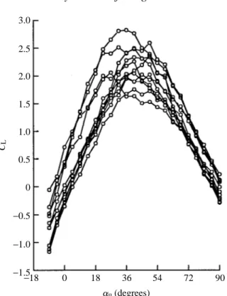
The development of lift with angle of attack
The flows created by the downstroke and flip also alter the growth of lift with angle of attack, dCL/dau (Table 1). However, there were only two cases in which the dCL/dau values were significantly different from that measured in pure translation. Following a 76.5 ˚ downstroke and rotation about the 0.2 and 0.5 chord axes, the growth of lift with angle of attack is substantially elevated (5.147 and 5.363, respectively). These values approach the theoretical limit of 6.28 for a thin plate at steady state (Prandtl, 1952). These two instances were also cases in which lift was generated at a 0 ˚ angle of attack, probably through the influence of the inter-vortex stream. It is clearly too simplistic to assume that this mechanism merely contributes a constant amount of lift to that generated during translation. Rather, the presence of the downstroke wake changes the dynamics of vortex growth and shedding over the first few chord lengths of motion, as can be seen by comparing the force trajectories in Fig. 2A with those in Fig. 9A. For example, through the influence of the inter-vortex stream, vortex shedding might begin at a lower upstroke angle than would be possible in pure translation. Unfortunately, I did not record an
2.5
2.0 3.0
1.5
1.0
0.5
0
−0.5
−1.0
−1.5 CL
0
−18 18 36 54 72 90 au(degrees)
extensive enough collection of flow visualizations under these conditions to test this hypothesis directly.
Comparisons with previous studies
The results of this modeling analysis warrant comparison with the similar study of Savage et al. (1979) for dragonfly flight at a Reynolds number of 8000. According to their analysis, there are two phases in the reconstructed dragonfly wing-beat cycle that provide substantial lift. The short downstroke generates a large leading edge vortex that is responsible for CL values of 0.87 during the subsequent ‘pause’ phase. In addition, supination is thought to generate lift (CL=2.3) due to suction as fluid flows rapidly around the leading edge of the wing. However, both these calculated coefficients are low compared with the coefficients measured directly on the Drosophila wing model. It likely that the assumptions required in predicting lift and drag forces from flow patterns are responsible for much of this discrepancy. One important experimental difference between the Drosophila and dragonfly models is that a 30 ˚ angle of attack was not sufficient to generate vortex shedding at a Reynolds number of 8000. This, in part, may explain why
B A
Savage et al. (1979) found no evidence for strong effects of upstroke (au=30 ˚) on force generation during the downstroke.
Ellington (1984c) presented a possible mechanism, ‘the flex’, by which circulation could develop more rapidly after an isolated supination. According to his scheme, the circulation generated by the downstroke and rotation is shed during rotation from a stationary trailing edge, combined with the starting vortex of the subsequent upstroke. As the circulation due to rotation increases, the counter-vorticity required by Kelvin’s law develops off the leading edge, eventually resulting in a separation bubble at the start of the upstroke. The flex scenario is comparable to the experiments in the present study in which auand adwere below the threshold for vortex shedding and the rotational axis was at the 0.8 chord point so that the trailing edge was relatively stationary during the flip. In general terms, the results verify that the counter-vorticity of rotation can be utilized by the subsequent translational stroke, although the precise details differ. As described in Fig. 3, the rotational vorticity is shed symmetrically in two vortices from both edges of the wing, as opposed to one trailing edge vortex. However, this situation may result from the finite temporal separation of translation and rotation in the kinematics of the model as well as from the fact that, unlike some real fly wings, the model profile could not bend. A more substantive difference is the structure of the counter-vorticity required by the growth of bound circulation during wing rotation. In all cases in which the downstroke angle was sufficiently low to produce steady circulation, subsequent wing rotation resulted not in a small leading edge bubble, but in a strong mirror vortex with a center about one half-chord from the surface of the wing. The large distance between the wing surface and the vortex means that its useful capture depends upon subtle kinematic parameters such as rotational axis and angular velocity. The strength of this vortex is probably greater than that Ellington envisioned, but the kinematics used for the physical model were based upon the ventral flip in Drosophila, which is a particularly fast supination (Zanker, 1990; Dickinson et al. 1993).
Although capture of the mirror vortex is an appealing mechanism, it may be of minor importance compared with the magnitude of lift augmentation following downstrokes at high angles of attack. Stroke angles are rather large in flies (Zanker, 1990), well above the predicted threshold for vortex shedding. It is likely that real wings begin supination surrounded, not by simple bound circulation, but by a complex vortex wake. As described in previous sections, such conditions can result in lift coefficients much greater than could be generated by a flip from a low downstroke angle.
The von Karman street, Strouhal number and aerodynamic performance
duration of one stroke has on force generation during the next stroke, it is reasonable to suggest that an insect may maintain a constant ratio (Kshed) between the length of each half-stroke (fl) and the distance between shed vortices within the von Karman street
(Un21):
Kshed = (fl)(Un21)21, (3)
where fis the stroke angle, l is the wing length and U is the wing velocity. However, (nlU21) is just the Strouhal number, thus:
Kshed = fSt . (4)
Therefore, the assumption that flies might match their stroke kinematics to the frequency of vortex shedding generated by wing motion predicts that stroke amplitude will be inversely proportional to Strouhal number. Although the Strouhal number is stable throughout much of the Re realm of biological interest, it is strongly dependent upon Re within the range important for the flight of small insect such as Drosophila. For most objects, vortex shedding first appears at a Reynolds number of about 50 with a Strouhal number of about 0.14 (Roshko, 1954; Schlichtling, 1979; Lugt, 1983). Strouhal number increases with Re, until Re reaches a value of about 400, where it eventually approaches an asymptote at a value of 0.21. Taking a measurement of D. melanogaster stroke angle from Zanker (1990) (135 ˚) and using a Strouhal number of 0.16 for a Reynolds number of 100 yields a Kshedof about 0.4. The exact magnitude of this number probably has limited importance, given the difficulties with interpreting three-dimensional flows from a two-dimensional analysis. However, since small and large flies are roughly similar in shape, we can use this estimate of Kshed to predict changes in stroke amplitude as a function of Reynolds number. Such a calculation predicts a variation in ffrom 2.86 to 1.90 rad (164–109 ˚) as the Reynolds number increases from 50 to 400. These values for f are reasonable, and small flies such as Drosophila tend to have larger wing-beat amplitudes than do larger species such as Calliphora, Phormia, Eristalis and Tipula (Nachtigall, 1966; Ellington, 1984a; Zanker, 1990; Ennos, 1989).
Limitations of the physical model
general principles that may be quite useful in analyzing the complex kinematics of animals during flight.
The results in this paper have indicated how the flows generated during one stroke and rotation can increase lift production in the subsequent stroke. However, it would probably be inappropriate to view these interactions solely as a means of maximizing flight performance. More impressive than the absolute augmentation in lift due to the kinematics of the preceding stroke is the sensitivity of aerodynamic performance to subtle changes in those kinematics. Small changes in either the duration or angle of attack of the downstroke, as well as in the angular velocity of stroke reversal, could produce substantial changes in lift and drag production during the successive half-stroke. Such sensitivity both necessitates the use of a sophisticated control feedback system (Wehrhan, 1987; Hengstenberg, 1991; Egelhaaf, 1991) and allows for remarkable aerial maneuvers (Wagner, 1986). A recent behavioral analysis has shown that Drosophila actively controls the timing of ventral flip rotations along with changes in stroke amplitude during visually induced turns (Dickinson et al. 1993). Since changes in the timing of rotation can be kinematically similar to changes in the axis of wing rotation (Ellington, 1984c), such behavior could generate large and rapid changes in flight control forces.
I wish to thank Karl Götz, Fritz Olaf-Lehman and Roland Strauss for intellectual and technical support during the execution of this work. This work was funded by the David and Lucille Packard Foundation and NSF Grant IBN-9208765.
References
DICKINSON, M. H. ANDGÖTZ, K. G. (1993). Unsteady aerodynamic performance of model wings at low Reynolds numbers. J. exp. Biol. 174, 45–64.
DICKINSON, M. H., LEHMANN, F.-O. ANDGÖTZ, K. G. (1993). The active control of wing rotation by Drosophila. J. exp. Biol. 182, 173–189.
EGELHAAF, M. (1991). How do flies use visual motion information to control their course? Zool. Jb. syst. Phys. 95, 287–296.
ELLINGTON, C. P. (1975). Non-steady-state aerodynamics of the flight of Encarsia formosa. In Swimming and Flying in Nature, vol. 2 (ed. T. Y. Wu, C. J. Brokaw and C. Brennen), pp. 783–796. New York: Plenum Press.
ELLINGTON, C. P. (1984a). The aerodynamics of hovering insect flight. I. The quasi-steady analysis. Phil. Trans. R. Soc. Lond. B 305, 1–15.
ELLINGTON, C. P. (1984b). The aerodynamics of hovering insect flight. III. Kinematics. Phil. Trans. R. Soc. Lond. B 305, 41–78.
ELLINGTON, C. P. (1984c). The aerodynamics of hovering insect flight. IV. Aerodynamic mechanisms. Phil. Trans. R. Soc. Lond. B 305, 79–113.
ENNOS, A. R. (1989). The kinematics and aerodynamics of the free flight of some Diptera. J. exp. Biol. 142, 49–85.
FREYMUTH, P. (1988). Propulsive vortical signature of plunging and pitching airfoils. AIAA J. 26, 881–883.
FREYMUTH, P. (1990). Thrust generation by an airfoil in hover modes. Exp. Fluids 9, 17–24.
HENGSTENBERG, R. (1991). Gaze control in the blowfly Calliphora: a multisensory, two-stage integration process. Sem. Neurosci. 3, 19–29.
KIYA, M. ANDARIE, M. (1977). A contribution to an inviscid vortex-shedding model for an inclined plate in uniform flow. J. Fluid Mech. 82, 223–240.
MAXWORTHY, T. (1979). Experiments on the Weis-Fogh mechanism of lift generation by insects in hovering flight. I. Dynamics of the fling. J. Fluid Mech. 93, 47–63.
MCCROSKY, W. J. (1982). Unsteady aerfoils. A. Rev. Fluid Mech. 14, 285–311.
NACHTIGALL, W. (1966). Die Kinematik der Schlagflügelbewegungen von Dipteren Methodische und analytische Grundlagen zur Biophysik des Insektenflugs. Z. vergl. Physiol. 22, 155–211.
NACHTIGALL, W. (1979). Rasche Richtungsänderungen und Torsionen swhwingender Fliegenflügel und Hypothesen über zugeordnete instationäre Strömungseffekte. J. comp. Physiol. 133, 351–355. PRANDTL, L. (1952). Essentials of Fluid Dynamics. London: Blackie and Son.
RILEY, N. (1974). Flows with concentrated vorticity: A report on Euromech 41. J. Fluid Mech. 62, 33–39.
ROSHKO, A. (1954). On drag and shedding frequency of two-dimensional bluff bodies. N.A.C.A. Tech. Note 3169.
SAVAGE, S. B., NEWMAN, B. G. ANDWONG, D. T.-M. (1979). The role of vortices and unsteady effects during the hovering flight of dragonflies. J. exp. Biol. 83, 59–77.
SCHLICHTLING, H. (1979). Boundary-Layer Theory. New York: McGraw Hill. SOKAL, R. R. ANDROHLF, F. J. (1981). Biometry. San Francisco: W. H. Freeman.
SPEDDING, G. R. (1992). The aerodynamics of flight. In Advances in Comparative and Environmental Physiology 11. Mechanics of Animal Locomotion (ed. R. McN. Alexander), pp. 51–111. London: Springer-Verlag.
SPEDDING, G. R. ANDMAXWORTHY, T. (1986). The generation of circulation and lift in a rigid two-dimensional fling. J. Fluid Mech. 165, 247–272.
TIMME, A. (1957). Über die Geschwindikeitsverteilung in Wirbeln. Ing. Arch. 25, 205–225.
WAGNER, H. (1986). Flight performance and visual control of flight of the free-flying housefly. (Musca domestica L.). I. Organization of the flight motor. Phil. Trans. R. Soc. Lond. B 312, 527–551. WEHRHAN, C. (1985). Visual guidance of flies during flight. In Comprehensive Insect Physiology,
Biochemistry and Pharmacology, vol. 6, Nervous System: Sensory (ed. G. A. Kerkut and L. I. Gilbert), pp. 673–684. New York: Pergamon Press.
WEIS-FOGH, T. (1973). Quick estimates of flight fitness in hovering animals, including novel mechanisms for lift production. J. exp. Biol. 59, 169–230.
WU, J. Z., VAKILI, A. D. ANDWU, J. M. (1991). Review of physics of enhancing vortex lift by unsteady excitation. Prog. Aerospace Sci. 28, 73–131.
ZANKER, J. M. (1990). The wing beat of Drosophila melanogaster. I. Kinematics. Phil. Trans. R. Soc. Lond. B 327, 1–8.