362
©IJRASET: All Rights are Reserved
Implementation of Turbo Codes for Noisy
Channels in LTE Systems
Sonal Laad
1, S. R. Mansore
21, 2Department of Electronics and Communication, UEC, Ujjain,
Abstract: Turbo codes can be viewed as a class of parallel concatenation of convolution codes which attain low Bit Error Rate in the waterfall region of the error even for relatively low Signal to Noise Ratio values. This paper presents an implementation of turbo codes. The approach used in this paper uses a recursive convolution encode due to good convergence of decoding at the receiving end. Block interleaving has been used to randomize or permute the bit stream. Puncturing has also been implemented to generate higher rate codes compared to the conventional r=1/3 encoder. This helps in generating higher rate turbo codes for noisy channels. Finally the decoding mechanism uses the soft input-soft output decoding. The performance of the system has been evaluated based on the bit error rate.
Keywords: Turbo Codes, Bit Error Rate (BER), Trellis structure, puncturing, Apriori information, a posteriori probability (APP).
I. INTRODUCTION
This Turbo codes are a class of high-performance forward error correction (FEC) codes which show extremely good BER performance near the Shannon’s limit [1]. For codes with relatively large code length, the bit error rate or probability of error (Pe) approaches zero if the transmission rate is less than the channel capacity[2] mathematically given by[2].:
(1) Here,
TR represents transmission rate through the channel. The Shannon’s limit is BER of almost 10-5 (ideally 0)for = 0 dB for binary
modulation [11]. The turbo codes can be thought of as a parallel concatenation of Convolutional codes. The structure of the turbo encoder and decoder in a communication system is shown in the fig.1
Fig.1 The Turbo Encoder-Decoder in a channel Outer
Encoder
Inner Encoder
Channel
Inner Decoder Outer
Decoder
363
©IJRASET: All Rights are Reserved
The turbo encoding can be thought of as a two-step process comprising of the inner encoder and the outer encoder [3]. The inner encoder, channel and outer encoder is often termed as the super channel. The block diagram of the turbo encoder is shown in fig.2
Fig.2 Turbo Code Encoding Mechanism [11]
The encoder inputs and outputs are: Input: I
Outputs: I, P1, P2 Here,
I represents the information bits P1 represents the Parity bit 1 P2 represents the parity bit 2
The interleaver is denoted by π
Turbo codes should look like random codes and the interleaver introduces the randomness. However, too much randomness can create a lot of decoding complexity. On the flipside, if the randomness is too low, i.e. there is too much structure in the code, then the code doesn’t remain random at all.
II. TURBOENCODING
The blocks in the turbo encoding part are:
1) Encoder 1
2) Encoder 2
3) Interleaver (π)
The information bit I is fed directly to one encoder and it’s interleaved version is fed to the other encoder. The outputs of encoder 1, encoder 2 andt he original information bit are fed to the channel. Often the output of encoder 1 is called parity bit 1, and the output of encoder 2 is called parity bit 2. If both the encoder structures are same, then such codes are called symmetric codes and they generally exhibit good convergence.
A. Encoder Structure
The encoder structure is extremely critical for turbo code design. The encoder structure is a recursive feedback encoding mechanism. It results in large inter code distance in the trellis structure. The conventional turbo code or the systematic turbo encoder has one input and 3 outputs and hence has a coder rate of
r=1/3 (2) The recursive structure at the encoder is used in the form of the system response of
Generally, recursive encoder design renders better intercede distance. Moreover, the parallel concatenation is better than serial concatenation since parallel concatenation based codes terminating easily.
Considering the response of the encoder block as G(D), and the input as U(D)=1,we get: (3)
(4)
(π)
Encoder2
Encoder1 I
P2
P2
364
©IJRASET: All Rights are Reserved
Then, the output of the encoder1 will be:(5) If the interleaver system function is given by
(6) Then, the input to encoder 2 will be,
[image:3.595.95.475.113.347.2](7) The recursive encoding structure can be understood as shown in fig.3
Fig. 3 Internal Encoder Structure
The interleaver spreads out the 1s in the input bit stream and feeds to encoder 2.This results in code word with large weights at the output [7]. This can be illustrated as:
Let the original information sequence be: 110000000000000
Then the interleaved bit sequence will be 1000000000000001
It can be seen that the bit 1 is spread out temporally in the code word.
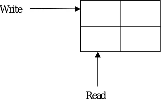
The most common interleaver structure used is the block interleaver. It this structure, the interleaver is fed row-wise and data is read column wise and vice-versa.
Fig.4 Block Interleaver structure
III.PUNCTURING
All Puncturing is a technique of generating codes of higher rate. In this technique, some of the bits are not transmitted at every time slot. Table.1 illustrates the concept [8].
At t1, I and P1 are transmitted At t2, I and P2 are transmitted At t3, I and P1 are transmitted
Thus the r=1/3 code is converted to a r=1/2 code. Hence, by puncturing, higher rate codes are obtained. The receiver assumes that for the non-transmitted bit, there exists equal probability for 0/1 transmission i.e.
P(0)=P(1) (8) The concept of puncturing can be understood using the following table
π
Write
[image:3.595.205.368.485.586.2]365
©IJRASET: All Rights are Reserved
TABLE I
Transmission Table For Puncturing
Bit Tx (Y/N) Tx (Y/N) Tx (Y/N)
I Y Y Y
P1 Y N Y
P2 N Y N
Time=t1 Time=t2 Time=t3
All At t1, I and P1 are transmitted At t2, I and P2 are transmitted At t3, I and P1 are transmitted
Thus the r=1/3 code is converted to a r=1/2 code. Hence, by puncturing, higher rate codes are obtained. The receiver assumes that for the non-transmitted bit, there exists equal probability for 0/1 transmission i.e.
P(0)=P(1) (9)
IV.NOISYCHANNELDESIGN
The channel assumed in this approach is the Gaussian channel with the frequency domain Power Spectral density of noise being constant[10]. Mathematically,
N(f)=k∀f (10) Here,
N stands for noise k is a constant f stands for frequency.
The time domain nature of the noise is random and resembles a random signal which is a function of time.
V. TURBODECODERDESIGN
[image:4.595.191.403.118.261.2]The turbo decoding mechanism is shown in fig.5
Fig.5 Structure of Turbo Decoder [11]
Dec 1
π Dπ
π
Dec
2 I
Xk
Y1k
Y2k
APP
366
©IJRASET: All Rights are Reserved
The turbo decoding mechanism uses two decoders working in synchronism in a recursive fashion[5]. Three inputs to both the decoders are the information bit X and the parity bit Y1 and Y2, all of which come from the channel. The second decoder receives an interleaved version of the parity bit Y2 so as to retain the sequence of the data stream [9]. The input 4 is the apriori information of the bit that the other decoder thinks the bit to be. Hence, decoder 1 sends the estimation of a bit along with its probability to decoder 2 and the same process is repeated by decoder 2 and data is sent to decoder 1. Thus, in place of decoding the bit at one go, the decoder tries to decoder encoder 1 first followed by decoding encoder 2. The decoding is carried on recursively and stopped on setting a conditions on iterations. The final verdict about the information bit I is taken from the decoder 2 after computing the a posteriori probability (APP) using the following relations.
(11)
= (12)
Here, x and y denote the probabilities of the bit being 0 or 1. Finally a hard decision output i.e. hard quantized output in the form of 1 or 0 is received.
VI.SIMULATIONANDRESULTS
The results obtained are plotted below. Fig.6, Fig.7 and Fig.8 show the patterns of the original signal, addition of noise in channel, and signal after addition of noise.
Fig.6 Original Signal before passing through channel
367
©IJRASET: All Rights are Reserved
Fig.8 Signal after addition of noise
Fig.9 BER performance of system
Fig.9 gives the comparison of BER performance of systems under consideration. It is observed that for given Eb/N0, proposed system shows better results
VII. CONCLUSIONS
It can be concluded from previous discussions that turbo codes are effective in attaining low BER in the approaching the Shannon’s limit. The system has been simulated on MATLAB. The results obtained and the related mathematical formulations that the proposed technique achieves significantly low BER at considerably low SNR values. The system employs block interleaving in Turbo Encoding for noisy channel conditions.
REFERENCES
[1] Lei Yang, Yixuan Xie, Xiaowei Wu, Jinhong Yuan, Xingqing Cheng, Lei Wan, “Partially Information-Coupled Turbo Codes for LTE Systems”, IEEE 2018. [2] Chaofan Chen , Li Li, Li Wang, Shuai Wang 1, Xiangming Li 1, George K. Karagiannidis, “Noncoherent Detection With Polar Codes”, IEEE 2018. [3] Saeedeh Moloudi, Michael Lentmaier, Alexandre Graell i Amat, “Spatially Coupled Turbo-Like Codes”, IEEE 2017.
[4] Suihua Cai, Nina Lin, and Xiao Ma, “Block Markov Superposition Transmission of BCH Codes with Iterative Erasures-and-Errors Decoders”, IEEE 2017. [5] Gianluigi Liva, Lorenzo Gaudio, Tudor Ninacs and Thomas Jerkovits, “Code Design for Short Blocks: A Survey”, IEEE 2016.
[6] Erdal Arıkan, Daniel J. Costello, Jr., Joerg Kliewer, Michael Lentmaier, Paul Siegel, Ruediger Urbanke, Michael Pursley, “Guest Editorial Recent Advances in Capacity Approaching Codes”, IEEE 2016.
[7] Boulat A. Bash, Dennis Goeckel, Saikat Guha, Don Towsley, “Hiding Information in Noise: Fundamental Limits of Covert Wireless Communication”, IEEE 2015.
[8] Zunaira Babar, Soon Xin Ng and Lajos Hanzo, “EXIT-Chart Aided Near-Capacity Quantum Turbo Code Design”, IEEE 2015.
[9] Michael Lentmaiery, Saeedeh Moloudiy, and Alexandre Graell i Amat, “Braided Convolutional Codes – A Class of Spatially Coupled Turbo-Like Codes”, IEEE 2014.
[10] Tsung-Yi Chen, Kasra Vakilinia, Dariush Divsalar, and Richard D. Wesel, “Protograph-Based Raptor-Like LDPC Codes”, IEEE 2014.
![Fig.5 Structure of Turbo Decoder [11]](https://thumb-us.123doks.com/thumbv2/123dok_us/1239859.649881/4.595.191.403.118.261/fig-structure-of-turbo-decoder.webp)
