Contour-based Hand Pose Recognition for Sign Language Recognition
Mika Hatano, Shinji Sako, Tadashi Kitamura
Graduate School of Engineering, Nagoya Institute of Technology
{pia, sako, kitamura}@mmsp.nitech.ac.jp
Abstract
We are developing a real-time Japanese sign language recogni-tion system that employs abstract hand morecogni-tions based on three elements familiar to sign language: hand motion, position, and pose. This study considers the method of hand pose recognition using depth images obtained from the Kinect v2 sensor. We ap-ply the contour-based method proposed by Keogh to hand pose recognition. This method recognizes a contour by means of discriminators generated from contours. We conducted exper-iments on recognizing 23 hand poses from 400 Japanese sign language words.
Index Terms: hand pose, contour, sign language recognition, real-time, Kinect
1. Introduction
In Japan, Japanese sign language is usually used among hear-ing impaired people to communicate. In addition, these people often communicate with others through a third person who un-derstands both oral and sign language. The alternative is to use a computer that acts as an interpreter. However, no practical sign language recognition system exists, even one that recog-nizes isolated words. The difficulties lie in the nature of vi-sual language and its complex structure. Compared with speech recognition, sign language recognition incorporates various vi-sual components, such as hand motions, hand poses and facial expressions. In addition, no established study exists on rep-resenting the structure of Japanese sign language in a similar manner to that of spoken language. Therefore, few attempts rec-ognize sign language by units such as hand motions and hand poses [1, 2].
Our study develops with real-time recognition of sign lan-guage words. In Japanese sign lanlan-guage, a sentence consists of several words and non-manual signals such as facial expres-sions. To recognize words is a first step and essential to recog-nize sentences. The number of Japanese sign language words is said to be 3,000 or more. Recognition by discriminators that are independent of every word has proven ineffective. To produce a practical system, analysis and reconstruction of sign language words are critical. We want to emphasize that database of sign language words is required when we analyze such words. How-ever, no established database currently exists for sign language recognition. Therefore, we employ a database from a comput-erized sign language word dictionary instead.
Our system is based on three elements of sign language: hand motion, position, and pose. This study considers the method of hand pose recognition for our system. Speeding up hand pose recognition is difficult, because of the number and va-riety of hand poses caused by rotations, altering the angle from the sensor, and diversities in bone structures. This study consid-ers a hand pose recognition using depth images obtained from a single depth sensor. We apply the contour-based method
pro-posed by Keogh [3] to hand pose recognition. This method rec-ognizes a contour by means of discriminators learned from con-tours. We conducted experiments to recognize 23 hand poses from 400 Japanese sign language words.
2. System overview
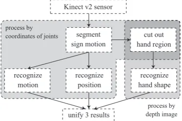
Figure 1 shows the flowchart of the entire system. We use Kinect v2 sensor [4] to obtain data from sign motions produced by an actual person. First, data obtained from the sensor is seg-mented into sign language words. Second, the three aforemen-tioned elements are recognized individually. Finally, the recog-nition result is determined by the weighted sum of each score. The recognition process of the hand pose and other two compo-nents employs depth data of the hand region and coordinates of joints, respectively. This study partially considers the method of hand pose recognition and does not discuss other processes on the flowchart.
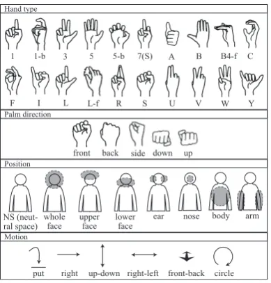
To utilize the structure in sign language recognition re-quires an expert knowledge of sign language. We apply a database from the computerized sign language word dictionary produced by Kimura [5] to sign language recognition. Our hand pose recognition is based on the classification of hand types employed in this dictionary. Table 1 shows a portion of the database in the dictionary. This database includes ap-proximately 2,600 Japanese sign language words. Each word is represented by specific sign language types in Table 2 and other elements are indicated in Figure 2. For example, the word “red” which belongs to the type 1 in Table 2 is expressed by the dominant hand and the other hand is not used.
3. Method of hand pose recognition
Some methods of hand pose estimation classify depth pixels into parts to obtain joint coordinates [6, 7]. However, these methods present difficulties when the palm does not face the
Kinect v2 sensor
segment sign motion
recognize motion
recognize position
recognize hand shape
unify 3 results
process by coordinates of joints
process by depth image
[image:1.595.333.520.593.717.2]cut out hand region
Table 1: Portion of the database in the dictionary.
Word
SL Type
Hand type
Palm
direction Position Motion love 3 B down NS circle between 4 B side NS down blue 1 B back lower face back red 1 1 back lower face right baby 4 B up NS up-down autumn 4 B back whole face front-back open 4 B front NS right morning 1 S side upper face down shallow 2 B side NS up tomorrow 1 1 front whole face front play 4 1 side upper face front-back rain 4 5 back NS up-down walk 1 U back NS front relief 4 B back body down say 1 1 side lower face front
[image:2.595.63.280.84.337.2].. .
Table 2: Sign Language (SL) types.
1 2 3 4 5 use both hands × ⃝ ⃝ ⃝ ⃝
hand type is same
through two hands ⃝ × ⃝ ×
non-dominant
hand moves × × ⃝ ⃝
camera and some fingers are invisible. We use the contour-based method proposed by Keogh [3]. Contour-contour-based methods work efficiently when recognition objects have distinct shapes. This method treats a contour that encircles an area as a recog-nition object and uses discriminators called wedges generated from contours. This method is described below.
3.1. Feature extraction
Shapes can be converted to distance vectors to form one-dimensional series. Figure 3 shows the procedure for extracting a distance vector from a hand image. First, the center point of the hand region is determined by distance transform. Distance transform labels each pixel whose value is “1” with the distance to the nearest pixel whose value is “0” in a binary image. The center point is a pixel that has a maximal value after distance transform. Next, each distance from the center point to every pixel on the contour is calculated. The distance vector repre-sents a series of these distances.
3.2. Calculation of distance
A distance D between two distance vectors P =
{p0, p1, ..., pn} and Q = {q0, q1, ..., qn} is calculated according to the followings.
D(P, Q) = v u u t
n ∑
i=1
(pi−qi)2 (1)
If the length of two distance vectors is different, dynamic time warping (DTW) should be used to adjust for size variations. However, we do not use DTW to avoid excessive computation time. Instead, we unify their length by resizing them in advance. We can compare contours by calculating their distances or using discriminators generated from contours. These discrim-inators are called wedges. Wedges have maximal and min-imal values at each point. If a contour is located inside a
front back side down up
1 1-b 3 5 5-b 7(S) A B B4-f C
F I L L-f R S U V W Y
whole face
upper face
lower face
ear nose body arm NS
(neut-ral space)
right up-down right-left front-back circle put
Hand type
Palm direction
Position
[image:2.595.367.485.304.384.2]Motion
Figure 2: Elements in sign language dictionary.
Depth Image (Original Image)
Distance Transform
Contour and Center Point
Distance from center point
Figure 3: Feature extraction from an image of a hand region.
wedge, the distance is 0. The distanceDbetween a wedgeW
(U={u0, u1, ..., un}is its top,L={l0, l1, ..., ln}is its bot-tom) and a contourP ={p0, p1, ..., pn}is calculated based on the following equation. For example, the sum of broken lines in Figure 4 is a distance betweenWandP.
D(W, P) = v u u u t
n ∑
i=1
(pi−ui)
2
(pi> ui) (pi−li)
2
(pi< li) 0 (otherwise)
(2)
3.3. Producing wedges
Wedges are produced according to the following procedures.
1. Extract features from hand images.
2. Calculate distances of all contours.
3. Unify two contours in ascending order of distances. The maximal and minimal values of merged contours become a wedge.
4. Repeat process 3. until the number of wedges decreases to a definite number.
W U
[image:2.595.357.492.666.720.2]L P
5 wedges 3 wedges 2 wedges 1 wedge
Figure 5: Producing wedges from five contours.
When Figure 5 shows an example of producing wedges. A wide wedge produced by contours that are diverse does not function as a discriminator. We prepare various wedges for recognizing each hand type in order to consider the details of contours.
3.4. Speeding up calculation
When we consider a rotation invariant matching of two distance vectors, the calculation must be repeated many times with shift-ing one of the distance vectors. We can speed up this com-putation by aborting when the current sum of squared differ-ences exceeds a threshold. In addition, although existing re-search does not attempt this, we try to speed up the calculation by means of the followings.
• The length of the distance vectors is unified and short-ened, and the accuracy does not diminish.
• When the number of wedges per hand type is greater than one, recognition that uses one-by-one wedge is per-formed prior to help targeting candidates.
4. Experiments
4.1. Datasets
We conducted experiments on recognizing 23 hand poses in 400 Japanese sign language words in the national sign language test grade 5. To recognize these 400 words requires to distinguish 23 hand poses in Table 3 defined by hand types and palm di-rections. Some words have the same hand poses but different position and motion. Our system distinguish each word after recognizing 3 components and unifying recognition results.
Because hand shapes transform with motions, each hand type remains independent even if the palm direction is different. However, some exceptions exist to distinguish sign language words that have the same motion, position, and hand type, but have a different palm direction. For example, Groups 3 and 4 in Table 3 should be distinguished even though the hand type is the same.
To simplify the collection of data in our experiments, we used depth images of stationary hands instead of those obtained during natural sign motions. Table 4 shows the experimental conditions. We conducted four experiments examining the ro-bustness of the recognition method about the variety of hand shapes and the computation time. The objectives of the experi-ments are described as follows.
Experiment 1 Recognize 100 hand images by wedges pro-duced from the same 100 images per hand type, palm direction, and tester (close-dataset, close-tester).
Experiment 2 Recognize 50 hand images by wedges produced from the other 50 hand images per hand type, palm
direc-Table 3: List of 23 hand pose groups.
ID Hand type Palm direction
0 1 front-back, right-left
1 1-b right-left
2 3 front-back
3 5 front-back
4 5 up-down
5 5-b front-back, right-left, up-down
6 7(S) front-back
7 A front-back, right-left
8 B front-back
9 B right-left
10 B up-down
11 B4-f right-left
12 C right-left
13 F front-back
14 I front-back
15 L front-back
16 L-f right-left
17 R right-left
18 S front-back, right-left, up-down
19 U front-back
20 V front-back
21 W front-back
[image:3.595.322.524.72.444.2]22 Y front-back
Table 4: Experimental condition.
Hand type 20 types in Figure 2
Palm direction 3 patterns (front-back, right-left, up-down)
Hand pose group 23 groups*
*determined by hand types and palm directions
Tester’s profile A (female, hand size* 16 cm)
B (female, hand size* 18 cm) C (male, hand size* 19 cm) D (male, hand size* 21 cm)
*measured from the wrist to the tip of the middle finger
Depth image 100×100 pixel
100 images of the hand region per tester, hand type and palm direction
Length of distance vector 30 or 180
PC specs OS:Windows 8.1 64 bit
RAM: 4 GB
CPU:Intel Core i5-4570 (3.20 GHz, 4-core)
tion, and tester (open-dataset, close-tester). Experiments were repeated with different data.
Experiment 3 Recognize 100 hand images of a person by wedges produced from 300 hand images of the other three persons per hand type, and palm direction (open-dataset, open-tester). Experiments ware repeated with different data.
Experiment 4 Examine the relationship between the compu-tation time required to recognize a hand image and the average recognition rate from Experiment 2. We at-tempted to speed up the calculation by the methods in Section 3.4. The threshold value when the calculation was aborted was determined by the preliminary experi-ment. The length of distance vectors was 30 in this ex-periment. Each recognition was aided to target candi-dates as many as five hand pose groups by the recogni-tion that uses one-by-one wedge performed prior.
4.2. Results
[image:3.595.358.496.87.304.2]4.2.1. Experiment 1, 2
[image:3.595.311.539.289.430.2]Number of wedges
Recognition rate (%)
length of distance vector: 180 length of distance vector: 30
{
Experiment 1
length of distance vector: 180 length of distance vector: 30
{
Experiment 2
1 5 10
[image:4.595.78.264.71.188.2]40 60 80 100
Figure 6: Experiment 1, 2: Recognition rate and number of
wedges per hand type and palm direction (person is known).
Experiment 1 was conducted with close-dataset. This ex-periment is just for sanity check and its condition is impossible in real-life. The result was sufficient for our system. Erroneous recognition in Experiment 1 was primarily caused by misiden-tifying hand pose Groups 4 and 5. These two groups have a common point that includes a hand pose whose palm direction is down. When we obtain data from a single depth camera, cap-turing the characteristics of hand shapes when the palm does not face the camera is difficult. Group 6 had the lowest recognition rate among the hand pose group (when the length of the distance vector is 180, the number of wedges was 10 per hand type and palm direction, and the group’s recognition rate was 80%). This is because the group was misrecognized as Group 0. These two groups have similar shapes. In addition, the recognition rates of Group 2, 13, 15, 20, and 22 were high under all conditions because other groups do not possess similar shapes.
Experiment 2 was conducted with open-dataset and close-tester. The result showed a similar trend to that of Experiment 1 concerning the causes of erroneous recognition. Because no hand shapes from the learning data are included in the evalua-tion data, the recognievalua-tion rate was lower than that of Experiment 1. However, no significant difference in recognition rate of Ex-periment 1 and 2 appeared when the number of wedges is one per hand type and palm direction. Therefore, if the wedges are generated from samples of a certain number, applying unknown data from the same person is possible. The recognition rate from Experiment 2 is expected to approach that of Experiment 1 by increasing the amount of learning data.
Experiments were conducted after changing the length of distance vectors. Although shortening the distance vectors re-duces the calculations, the accuracy is expected to fall because of the loss of detailed features. However, no significant differ-ences between the experiments appeared when the length of the distance vectors is 30 and 180. Therefore, if small sized hand images are used or the contours are rough because of noises, a robust recognition can be accomplished.
The maximal number of wedges was between 20 and 25 in Experiment 1 and between 8 and 13 in Experiment 2. The number fluctuated with the complexity of the hand types.
4.2.2. Experiment 3
Experiment 3 was tester-independent setup. Figure 7 shows the results of Experiment 3. The recognition rates shown are the results when the length of distance vectors is 30. If we change the length to 180, recognition rates do not change significantly. We specified causes of erroneous recognition when the number of wedges is 30 per hand type and palm direction. The results
Number of wedges
Recognition rate (%)
A B C D Test data
1 10 20 30
10 20 30 40 50
Figure 7: Experiment 3: Recognition rate and number of
wedges per hand type and palm direction (person is unknown).
A
B
C
D
Hand types (palm direction)
1(back) F(front) 5(down) 5-b(left) B(left)
[image:4.595.334.517.73.189.2]Tester
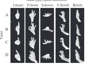
Figure 8: Variety of hand shapes among people.
show the same tendency as in Experiments 1 and 2, that is, 13 % of all data were misrecognized as Groups 4 and 5. The detailed findings for each hand pose group reveal the following: 41 % of Group 6 were misrecognized as Group 0, 53 % of Group 19 were misrecognized as Group 0, 45 % of Group 12 were misrecognized as Group 5.
The low recognition rate is due to individual differences in hand shapes caused by differences in bone structure and posing of hand shown in Figure 8. Wedges produced from the hand images of various people include other hand types. This caused misrecognitions.
Per person details show that the recognition rate was lowest when the system attempted to recognize hand poses of tester A, whose hand size was the smallest. When the number of wedges increases, the recognition rate of tester B, whose hand size is between that of A and C is higher than that of other testers.
Although we normalized the scale of distance vectors ac-cording to each hand size, hand pose recognition by contours possesses other difficulties when the bone structures are con-sidered. The accuracy diminishes when the system recognizes hand images of a person whose bone structure is dissimilar to any learning data. When we want to recognize hand poses of an unknown person, wedges generated from people who have similar bone structure should be used. Therefore, additional hand images that reveal various characteristics in bone struc-tures should be collected.
4.2.3. Experiment 4
[image:4.595.356.500.237.347.2]0 20 40 60 80 100 40
50 60 70
Computation time (ms)
[image:5.595.85.256.71.166.2]Recognition rate (%)
Figure 9: Experiment 4: Average computation time and the
recognition rate required to recognize a hand image.
When the person is known, 88 ms (corresponding to 11 fps) was required to recognize a hand image with 70 % accuracy. Recognizing all hand images obtained from the sensor with a frame rate of 30 fps is impossible. However, the number of frames required to specify a hand pose is limited because the hand pose does not change at every frame. We can recognize in real-time selected hand images by means of comparison method employing a small calculation such as image moment [8]. This experiment has been implemented in a single-thread. The pro-cessing speed can be improved by utilizing a high-speed tech-nique such as multi-threading.
5. Conclusion
We are developing a real-time Japanese sign language recogni-tion system based on three elements of sign language: morecogni-tion, position, and pose. This study examined hand pose recognition by means of contour-based method proposed by Keogh using depth images obtained from a single depth sensor.
We conducted experiments on recognizing 23 hand poses from 400 Japanese sign language words. Under the condition of close-tester, the recognition rate was approximately 90 % for close-dataset, 70 % for open-dataset. In addition, we con-ducted an experiment to recognize the hand poses of an un-known person by means of discriminators learned from hand poses of other people. The recognition rate dropped consider-ably because diversities in bone structure of each person’s hand generated loose discriminators that are unable to consider the details of contours. We also evaluated the computation time. Regarding close-tester and open-dataset, 88 ms (corresponding to 11 fps) was required to recognize a hand image with 70 % accuracy.
When we recognize the hand poses of an unknown person, discriminators generated from people who have similar bone structure should be used. Future research in this area requires that hand images of various people be collected and applied for the purpose of recognizing unknown persons.
6. Acknowledgement
This research was supported in part by Japan Society for the Promotion of Science KAKENHI (No. 25350666), and Toukai Foundation for Technology.
7. References
[1] Rung-Huei Liang and Ming Ouhyoung, “A Real-time Continu-ous Gesture Recognition System for Sign Language,” in Automatic
Face and Gesture Recognition, 1998. Proceedings. Third IEEE In-ternational Conference on, Apr 1998, pp. 558–567.
[2] Arata Sato and Koichi Shinoda, “Large Vocabrary Sign Language Recognition Based on Cheremes,” in IEICE Technical Report
PRMU2011-222, SP2011-137, 2012, pp. 155–160.
[3] Eamonn Keogh, Li Wei, Xiaopeng Xi, Sang-Hee Lee and Michail Vlachos, “LB Keogh Supports Exact Indexing of Shapes under Rotation Invariance with Arbitrary Representations and Distance Measures,” in 32nd International Conference on Very Large Data
Bases (VLDB2006), 2006, pp. 882–893.
[4] Kinect for Windows, http://kinectforwindows.org.
[5] Tsutomu Kimura, Daisuke Hara, Kazuyuki Kanda and Kazunari Morimoto, “Expansion of the System of JSL-Japanese Electronic Dictionary: An Evaluation for the Compound Research System,” in
Proceedings of the 2nd International Conference on Human Cen-tered Design, ser. HCD’11, 2011, pp. 407–416.
[6] Hui Liang, Junsong Yuan and Daniel Thalmann, “Parsing the Hand in Depth Images,” Multimedia, IEEE Transactions on, vol. 16, no. 5, pp. 1241–1253, Aug 2014.
[7] Danhang Tang, Tsz-Ho Yu and Tae-Kyun Kim, “Real-Time Artic-ulated Hand Pose Estimation Using Semi-supervised Transductive Regression Forests,” in Proceedings of the 2013 IEEE International
Conference on Computer Vision, ser. ICCV ’13, 2013, pp. 3224–
3231.