A Grating-Based OCDMA Coding–Decoding System
Incorporating a Nonlinear Optical Loop Mirror for
Improved Code Recognition and Noise Reduction
Ju Han Lee, Member, OSA, Peh Chiong Teh, Member, OSA, Periklis Petropoulos, Member, OSA,
Morten Ibsen, Member, OSA, and David J. Richardson, Member, OSA
Abstract—We demonstrate an elementary grating-based optical code division multiple access (OCDMA) code generation and recognition system incorporating a nonlinear optical loop mirror (NOLM) within the receiver. We show that the NOLM can act as a nonlinear processing element capable of reducing both the pedestal associated with conventional matched filtering and the width of the associated code-recognition pulse. The pedestal rejection allows for an improved code recognition signal-to-noise ratio (SNR) relative to simple matched filtering alone, and reduced intra- and interchannel interference noise due to code overlap. The system benefits of using the NOLM are experimentally demonstrated under both single- and multiuser operation within a variety of seven- and 63-chip 160-Gchip/s code generation, recog-nition, and transmission experiments based on the use of bipolar superstructure fiber Bragg grating (SSFBG) coding–decoding pairs. Incorporation of the NOLM is shown to allow error-free penalty-free operation at data rates as high as 2.5 Gb/s under single-user operation, and to provide error-free performance with reduced power penalty in two-user experiments. The narrowed pulse recognition signature offers major advantages in terms of the further all-optical processing of decoded signals, such as code regeneration and recoding.
Index Terms—Gratings, optical code division multiple access (OCDMA), optical fiber communication, optical fiber devices, optical signal processing, optical switches.
I. INTRODUCTION
T
HE CONTINUED rapid growth of Internet traffic demands the development of optical networks of ever-in-creasing capacity and functionality. It is clear that when developing such future networks it will be desirable, if not essential, to perform as much as possible of the processing and routing of signals directly within the optical domain. In this way, many of the bottlenecks currently imposed by optoelectronic conversion and electronic processing of data can be removed.All-optical pattern generation and recognition are two such signal-processing functions that are likely to be required in future high-capacity optical networks. These functions will be needed, for example, for header recognition in ultrafast optical time division multiplexing (OTDM) packet-switched networks, and for use within optical code division multiple access (OCDMA) systems [1], [2]. OCDMA is the optical
Manuscript received February 6, 2001; revised August 15, 2001.
The authors are with the Optoelectronics Research Centre, Univer-sity of Southampton, Highfield, Southampton, SO17 1BJ, U.K. (e-mail: [email protected]).
Publisher Item Identifier S 0733-8724(02)00378-X.
analog of the CDMA technique that has been applied with such success to the field of mobile communications. CDMA is a spread-spectrum digital transmission technique that allows multiple users of a network to share the same relatively broad transmission bandwidth through the allocation of specific mathematically defined codes that dictate how individual users use or sample the available spectral bandwidth in order to both send and receive data. There are two main types of techniques used to spectrally code and spread a data signal; these are the so-called direct-sequence (DS) CDMA, and frequency-hopping (FH) CDMA. However it is also possible to use hybrid ap-proaches that combine the two techniques [3]. In DS-CDMA, the digital data is directly coded with pseudorandom patterns in the time domain, and the receiver knows how to generate the same code and correlates the received signal with that code to extract the data. By contrast, in FH-CDMA, the signal is rapidly switched between different frequencies within the hopping bandwidth pseudorandomly, and the receiver knows beforehand where to find the signal at any given time. OCDMA is still in the very earliest stages of technological development; however, it is attractive for a number of reasons, including the capacity for high connectivity, more flexible bandwidth usage, asynchronous access, and improved system security.
We recently demonstrated a number of DS-CDMA systems based upon fiber Bragg grating encoding–decoding devices [4]. These particular experiments showed the suitability of using su-perstructure fiber Bragg grating (SSFBG) technology for the generation, recognition, and recoding of phase-encoded optical code sequences containing as many as 63 chips at chip rates as high as 160 Gchip/s. Longer code sequences and higher chip rates should also be possible.
An SSFBG can be defined as a standard fiber grating, i.e., a grating with a rapidly varying refractive index modulation of uniform amplitude and pitch, onto which a slowly varying refractive index modulation has been applied along its length. It can be readily proven that the impulse response of a weakly reflecting SSFBG (reflectivity less than 20%) follows pre-cisely the same form as the slowly varying superstructure refractive-index profile [5]. We produce our SSFBGs using a continuous grating-writing method that enables us to write fiber Bragg gratings on a grating-plane-by-grating-plane basis, and that allows the fabrication of gratings with highly complex refractive index profiles [6]. SSFBGs can, thus, be designed and fabricated with a wide range of complex tailored impulse-response functions with precise amplitude and phase
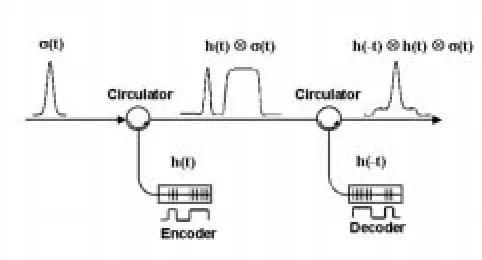
Fig. 1. Basic principle of pulse encoding and decoding by SSFBGs.
characteristics. Such SSFBGs should find application within a variety of optical-pulse processing systems [7], [8], including use within both DS-OCDMA code generation and recognition devices, and for which precise control of the amplitude and phase of the temporal pulse profile is essential. SSFBG technology represents an attractive means to produce compact and poten-tially low-cost components for such applications relative to the more conventional technological approaches, such as planar lightwave circuits [9], arrays of discrete fiber gratings [10], bulk grating-based systems incorporating spatial light modulators [11], and arrays of fiber couplers [12].
Fig. 1 shows the basic principle of pulse encoding and de-coding by SSFBGs. When a short pulse enters the SSFBG en-coder, the resulting reflected signal represents a coded sequence of distinct, time-spread pulses (the individual pulses that make up the code sequences are commonly known as chips). The in-dividual chip duration, the code sequence, and code length are defined by the SSFBG impulse response, which, as discussed previously, is given by the SSFBG refractive-index profile. The coded pulse sequence is then transmitted along an optical fiber to the decoder–receiver. The decoder operates on the principle of matched filtering, and, as such, is based upon purely linear optical effects. The matched filtering operation is realized, in practice, by reflecting the coded pulses from a grating with the spatially reversed superstructure profile of the encoder grating and which, thus, has the temporally reversed impulse response (phase-conjugate frequency response). Consequently, the pulse reflected from the decoder grating represents the cross- corre-lation function between the codes used within the encoder and decoder SSFBGs. In the instance that the codes are matched the reflected pulse represents the autocorrelation function of the en-coded pulse sequence.
High-quality code generation and recognition in the time do-main can be obtained by this method [13]. Unfortunately, as one moves to longer code lengths, higher data rates, and multiuser op-eration, undesirable phenomena can come into play that reduce the quality and contrast of the pattern-recognition signature and begin to adversely affect the quality of the system performance. Such undesirable phenomena can include decoherence of the re-fractive index profile along the grating length due to fiber diam-eter inhomogeneity or errors in the writing process itself, adja-cent code (intrachannel) interference, and interchannel interfer-ence. However, one can envisage incorporating additional non-linear components within SSFBG-based processing schemes to
either improve the performance, in such instances, or to extend the functionality of this technical approach.
In this paper, we report, for the first time, both theoretical and experimental results concerning the use of a self-switching nonlinear optical loop mirror (NOLM) within a time-spreading DS-OCDMA system to act as a fast saturable absorber with which to improve the quality of the code recognition signature. The use of a nonlinear thresholding device for increasing the contrast of the pattern recognition signature at a OCDMA receiver has been previously suggested and demonstrated [14], [15]. These previous demonstrations were based on either two-photon absorption in a semiconductor detector [14] or non-linear spectral broadening filtering in an optical fiber followed by long-pass filtering of the nonlinearly generated spectral components [15]. Both approaches have been shown to be capable of enhancing the decoded signal contrast in single-pass encode–decode systems. Our particular approach differs sub-stantially in a number of regards from these earlier works. First, although we use fiber-based Kerr nonlinearity as the basis of the switch, we also use a completely different physical imple-mentation of the thresholder, i.e., an interferometric NOLM device. Second, we use soliton effects to enhance the nonlinear discrimination and pulse evolution, which is important because it allows for pulse-shape restoration as well as nonlinear thresholding. It should also be appreciated that this approach, in contrast to the previously mentioned fiber-based technique, does not result in a wavelength shift of the processed signal. These latter points are extremely important if onward all-optical processing of the coded bit after decoding is required. Such an onward processing function might include recoding, for which a pulse duration substantially shorter than the chip duration is required in order to obtain a sufficiently distinct recoded data bit, and for which wavelength translation is likely to be undesirable. Note that NOLMs have already been adopted for various other optical processing applications, including pulse laser compression [16], extinction ratio improvement of optical time domain multiplexing (OTDM) systems [17], all-optical channel demultiplexing [18], and filtering of amplified spon-taneous emission (ASE) noise [19]. We show that a suitably designed NOLM can significantly improve the contrast of a degraded pattern recognition signature due to the imperfect matching of SSFBG parameters, and that it can reduce both intrachannel and interchannel interference noise.
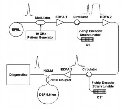
Fig. 2. Configuration of a seven-chip time spread DS-OCDMA system incorporating a NOLM. The saturated output power from erbium-doped fiber (EDFA) 3 was 15 dBm. The length of DSF in the NOLM was 6.6 km and the dispersion of the DSF was 1.18 ps/nm/km. The insertion loss of the encoder and decoder gratings was10 dB in each instance. Note that EDFA2 was included in the system to compensate for the loss of the encoding grating and associated circuitry in order to prevent the signal power from falling below010 dBm at any point within the setup. This ensured a high optical signal-to-noise ratio (SNR) was maintained throughout the system. EDFA3 did, in fact, have sufficient gain to operate the NOLM without the incorporation of EDFA2. However, in this instance, there was a significant system power penalty due to the increase in amplifier noise caused by the higher gain requirement.
noise are successfully demonstrated. In Section IV, we draw conclusions regarding our results and discuss further extensions and applications of the technology.
II. THEORETICAL ANDEXPERIMENTALANALYSIS ON
IMPROVEDPERFORMANCE OF ASEVEN-CHIPTIMESPREAD
DS-OCDMA SYSTEMUSING ANOLM
The configuration for the seven-chip time-spread DS-OCDMA system that we used to first validate the nonlinear cod-recognition signature enhancement concept described above is shown in Fig. 2. The system comprised a 2.5-ps 10-GHz regeneratively mode-locked erbium fiber ring laser (EFRL) with an external 10-GHz pulse selector, a seven-chip coding SSFBG, a matched seven-chip decoder SSFBG, two low-noise amplifiers to compensate for the system losses, a power amplifier to boost the power of the decoded signal, and a NOLM for nonlinear processing of the matched-filtered signal. Short pulses from the laser data modulated and launched onto the coding SSFBG resulted in the generation of a code sequence corresponding to the impulse response of the coding grating. In this instance, the particular code was bipolar with the required phase shifts distributed within the grating in accordance with the seven-chip M-sequence code “0 100 111.” The chip length of the gratings used in our experiments was 6.4 ps, corresponding to a chip rate of 160 Gchip/s. The coded pulse sequence had a total duration of 45 ps. The coded pulses were then launched onto the decode grating.
The temporal form of the pulses reflected from the decoder grating thus represented the cross-correlation function between the incoming encoded sequence and the decoder grating’s impulse response function. Assuming that the encoder–de-coder gratings are well matched, then our specific choice of a seven-chip M sequence ensures a good pattern recognition signature that has the form of a short chip-length long auto-correlation spike on a relatively low-level broad pedestal. The pedestal has a total duration of twice the code length (i.e., 90 ps). We quantified the performance of the particular gratings used in these experiments in an earlier work which showed that the precision of our grating writing was such that we could indeed obtain excellent pattern recognition signatures using the matched filtering approach [4]. In the current experiments, we amplified the decoded pulses to a high power and then passed the amplified pulses through the NOLM in order to selectively pass the correlation spike and filter out the low-level pedestal prior to detection. This nonlinear processing serves to further improve the SNR of the pattern-recognition signature and to reshape the correlation spike.
In order to theoretically validate our system concept, and to establish our optimum NOLM design, we first modeled this system as a function of the key parameters of the NOLM (e.g., coupling ratio, dispersion and length) and the peak power of the decoded pulse incident to the NOLM. We assumed the SSFBGs to be perfectly matched and to behave as idealized seven-chip M-sequence coders and decoders. Pulse propagation within the NOLM was modeled using the nonlinear Schrödinger equation with group velocity dispersion, self-phase modulation, intra-pulse Raman scattering, and self-steepening, and shock forma-tion at a pulse edge [20] as described by (1)
(1)
where pulse amplitude is normalized such that represents the optical field strength within the fiber. is the group delay, is the first order group velocity dispersion (GVD), and is the second-order GVD. represents the absorption coefficient of optical power in the fiber and corresponds to 0.25 dB/km,
is the signal frequency, and is the
nonlinearity coefficient where m /W and
m is the effective area of the fiber. fs has its origin in the delayed Raman response and represents the first-order Raman gain effects. (Note that, in fact, neither Raman scattering, self-steepening, nor third-order dispersion plays a significant role in the evolution of pulses of order the chip length over the 6-km propagation lengths considered herein.)
(a)
[image:4.612.42.283.59.498.2](b)
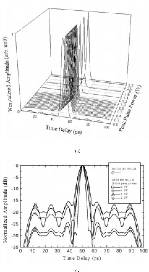
Fig. 3. Theoretical calculation showing the predicted impact of the NOLM on both the autocorrelation signal reshaping and pedestal rejection as a function of input pulse power. (a) Actual pulse shape evolution as a function of increasing input pulse peak power. (b) Same data plotted in a log scale.
parameter , dispersion slope , and nonlinearity coeffi-cient assumed within our calculations were 1.18 ps/nm/km, 0.07 ps/nm /km, and 1.55 W Km , respectively, at the system-operating wavelength of 1558 nm and corresponded to those of a fiber that was available within our laboratories. The fiber length was 6.6 km.
In Fig. 3, we present the results of our theoretical calculations, which show the predicted impact of the NOLM on both the au-tocorrelation signal reshaping and pedestal rejection as a func-tion of input pulse power. In Fig. 3(a), we plot the pulse shape evolution as a function of increasing input pulse peak power. Fig. 3(b) is a log-scale plot of the same data. The pulse shape of the simple matched filtered decoded signal for the particular seven-chip bipolar pulse sequence used in our experiments is given by the 0-W pulse form in Fig. 3(a). (Note that the indi-vidual pulse shape at each power is normalized with respect to
the peak pulse amplitude.) It can be seen that, as the decoded signal power is increased, the relative height of the ripple fea-tures associated with the pedestal decreases and the central au-tocorrelation feature narrows significantly.
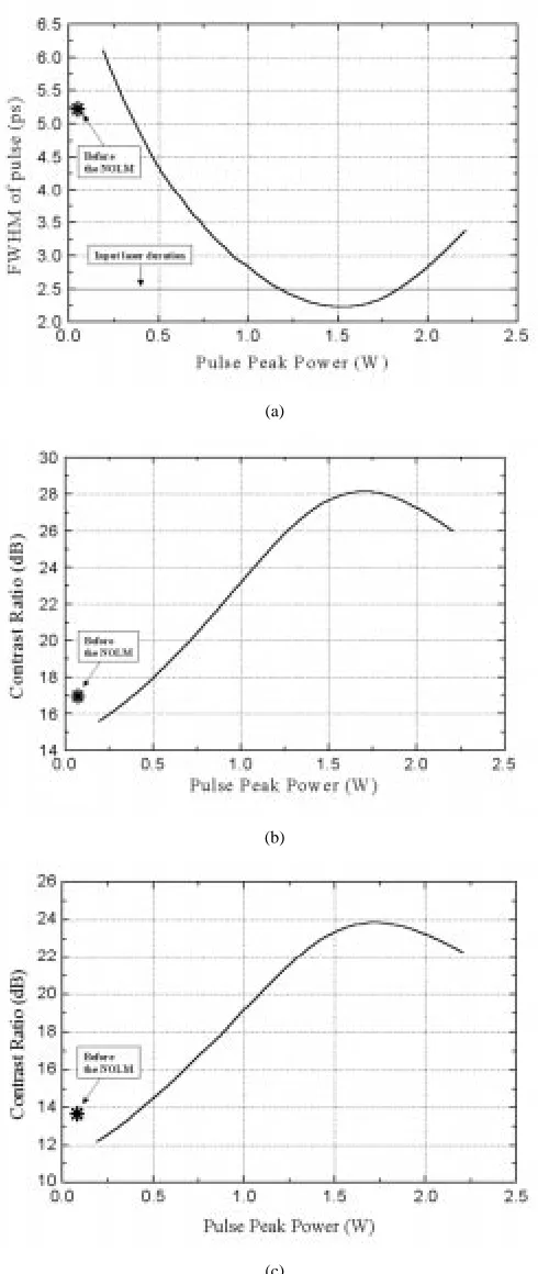
These features are summarized more fully in Fig. 4(a)–(c). In Fig. 4(a), we plot the half width of the central autocorrelation feature as a function of input power. It is seen that optimum com-pression with comcom-pression factors approaching 3 are obtained at a pulse peak power of 1.5 W. Note that, for a peak power of 1.2 W, the pulse duration is 2.5 ps, essentially the same as that of the input laser pulses. In Fig. 4(b), we plot the corresponding value of the signal contrast, which we define as the ratio be-tween the peak power of the output pulse to that of the first pedestal lobe. After simple matched filtering alone (i.e., before the NOLM), this ratio is 17 dB. However, this can be increased by as much as 10 dB at a peak power of 1.6 W and represents the optimum contrast enhancement in this instance. An 8–9-dB contrast enhancement is achieved at a peak power of 1.2 W. In Fig. 4(c), we quantify the improvement in contrast ratio in terms of the measured SHG autocorrelation of the decoded pulse form, since, in practice, it is this that we measured directly in our pre-liminary experiments. A factor of 3 reduction in pulse width and a peak contrast ratio enhancement factor of order 10 dB is again predicted. The pulse width contraction and nonlinear fil-tering result from high-order soliton effects within the NOLM [21]. These calculations, and others over a broader parameter space than described so far, show that for optimal pulse com-pression we require a 70 : 30 coupling ratio, a soliton order of within the 70% coupling direction within the loop, and the loop length to be of order the soliton period. (The relevant pulse duration for calculating the soliton period and order in the above is given by the half width of the correlation spike incident to the loop.)
In Fig. 5, we plot the predicted reflectivity of the NOLM as a function of input peak power. The NOLM is predicted to transmit 12% of the incident decoded pulse power at low intensities, with this percentage increasing to 78% at a pulse power of 1.8 W. The reflectivity at 1.5–1.6 W incident power, the optimum power in terms of minimum pulse duration–contrast enhancement, is 70%. In Fig. 5, we also plot the experimentally determined reflectivity as a function of incident power. The amplifier used in this particular experiment limited our maximum achievable peak power to 1.2 W, which, although slightly less than optimum, still allowed for significant switching, pulse shaping, and contrast enhancement. The experimentally observed nonlinear increase in NOLM transmission closely follows the predicted theoretical form, and approaches 40% at the 1.2-W level. In Fig. 6, we plot the experimental and theoretical SHG autocorrelation functions at a peak power of 1.2 W, both before and after the NOLM. Excellent agreement between theory and experiment is observed in both cases, in terms of both pedestal suppression and pulse narrowing. The final deconvolved pulse duration after the NOLM is 2.6 ps, essentially the same as the input pulseform and exactly as predicted in Fig. 4(a).
par-(a)
(b)
[image:5.612.44.289.63.643.2](c)
Fig. 4. (a) FWHM of the central autocorrelation feature as a function of input power. (b) Corresponding value of the signal contrast defined as the ratio between the peak power of the output pulse to that of the first pedestal lobe. (c) Contrast ratio in terms of the measured second harmonic generation (SHG) autocorrelation of the decoded pulse form.
ticular M sequence and the quality of these seven-chip bipolar gratings are so good that error-free penalty-free operation can readily be achieved with matched filtering alone. The benefits of the NOLM as a pulse-cleaning element only really become
Fig. 5. The predicted and measured reflectivity of the NOLM as a function of the input peak power.
(a)
[image:5.612.307.552.68.235.2](b)
Fig. 6. Experimental and theoretical SHG autocorrelation functions at a peak power of 1.2 W both (a) before and (b) after the NOLM. Solid lines: experimental measurements; dashed lines: theoretical calculations.
[image:5.612.306.551.284.673.2]gratings, which can lead to a degradation of decode signal quality as a result of the difficulty in maintaining coherence of the grating structure over the longer physical length of the grating during fabrication. Moreover, the use of longer codes means that interference noise due to temporal overlap of adja-cent coded data bits occurs once the length of the decode signal (which is two times the code length) becomes longer than the reciprocal of the data rate. The presence of this interference noise can significantly affect the system performance, even under single-user operation of the system. Similar interference noise is also generated once there are simultaneous users of the system, transmitting either synchronously or asynchronously over the same fiber. In order to demonstrate these features, we performed detailed system measurements on an OCDMA system similar to that described previously for seven-chip codes, only this time with 63-chip code sequence bipolar SSFBGs. These experiments are described, in detail, in the next section. Note that the use of longer codewords is desirable in real OCDMA systems because they support the use of a greater number of simultaneous users. In the case of seven-chip codes, there are just two bipolar M-sequence codes, which offers little scope for real system applications. In the case of 63-chip codes based on Gold sequences, as used in our experiments, there are 65 orthogonal bipolar code combinations [22], allowing the support of up to 65 simultaneous users.
III. CODE-RECOGNITIONPERFORMANCEIMPROVEMENT OF A
63-CHIPTIMESPREADGRATING-BASEDOCDMA SYSTEM
USING ANOLM
Our experimental setup for the 63-chip 160-Gchip/s system experiments is shown in Fig. 7(a) and is similar in principle to the seven-chip setup. In this instance, the 2.5-ps pulse at 10 GHz was first gated down to a lower repetition frequency and en-coded with pseudorandom data at either 1.25 or 2.5 Gb/s. The data pulses were then split using a 3-dB coupler and fed onto two separate encoder gratings, denoted C1 and C2, respectively, before being recombined into a single fiber using a second 3-dB coupler. The individual encoding SSFBGs contain phase-coding information within their refractive index profiles, as defined by two orthogonal 63-chip bipolar Gold codes. Once the data pulses are reflected from gratings C1 and C2, they generate two distinct data streams encoded with either one of these two dis-tinct codes. In Fig. 7(b), we plot both the distribution of the phase changes along the gratings, as defined by the two Gold sequences selected, and their corresponding spectral responses. The spiky reflectivity spectrum observed results from the mul-tiple phase jumps within the spectrum and is as theoretically expected. The chip duration for these gratings is 6.4 ps, and the chip rate 160 Gchip/s. The coded data bits have a total duration of 400 ps, as illustrated in Fig. 8(a) and (b), in which we plot both the theoretically predicted and experimentally observed re-sponses of gratings C1 and their corresponding conjugates C1 after excitation with 2.5 ps pulses. Although the response time of the detection system used to measure these pulses was in-sufficient to precisely resolve the individual chips, a clear cor-relation between theory and the experimental data is observed, confirming the high quality of the gratings.
The coded data stream was then either fed directly to de-code grating C1 or else transmitted over 25 km of standard single-mode fiber whose dispersion was compensated over a 5-nm bandwidth using a suitably linearly chirped fiber Bragg grating and then fed to grating C1 . Grating C1 was designed to provide a matched filter response to grating C1. The de-coded output from grating C1 was then either detected di-rectly or amplified in EDFA3 before being passed through the NOLM prior to detection. The NOLM used in the 63-chip ex-periments was the same NOLM used in the previously described seven-chip experiments. The pulse shaping properties of the in-dividual gratings, and of the gratings when used in conjunction with the NOLM, were characterized in the temporal domain using a fast p-i-n diode and sampling oscilloscope of combined 20 GHz bandwidth and a SHG autocorrelator ( 100 fs reso-lution). The system error rate performance was measured using a BER test set with up to 10-Gb/s measurement capability. Note that we ensured that there was a significant difference in pas-sage time through the system for each of the individually coded data streams so as to remove any direct correlation between the data arriving at the receiver from the two channels. Moreover, the relative passage time of the two channels could be fine tuned to allow anywhere between zero and full temporal overlap of the coded data bits at the receiver.
A. Single-Channel Operation
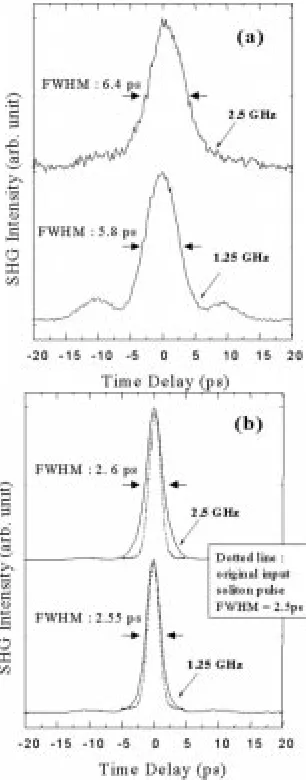
Disconnecting the fibers connected to grating C2 in Fig. 7(a) allowed us to make single-user experiments using gratings C1 and C1 . We performed encoding–decoding and associ-ated transmission experiments at data rates of both 1.25 and 2.5 Gb/s. In Fig. 9(a), we show the SHG autocorrelations of the central correlation spikes of the decoded pulseforms prior to the NOLM and directly after the decoder grating for bit rates of both 1.25 and 2.5 Gb/s. This particular data was taken with no intermediate transmission of the coded data bits. The decoded pulseforms have a deconvolved temporal half width of 6.4 ps at 2.5 Gb/s, and 5.8 ps at 1.25 Gb/s, and exhibit an appreciable pedestal component, which extends 400 ps from the central correlation spike. as can be seen in the eye diagrams shown in Fig. 10(b).
(a)
[image:7.612.104.494.65.672.2](b)
Fig. 7. (a) Experimental setup for the 63-chip 160-Gchip/s system experiments. (b) Two 63-chip bipolar Gold codes and the corresponding spectral profiles of the encoder SSFBGs that were fabricated.
in Fig. 11. These measurements showed that high-quality error-free performance could be obtained at both data rates, albeit with a power penalty relative to back-to-back
Fig. 8. Theoretically predicted and experimentally observed response of (a) gratings C1 and (b) their corresponding conjugates C1 after excitation with 2.5-ps pulses. Solid lines: experimental measurements; dashed lines: theoretical plots. The detection bandwidth of the experimental measurement (20 GHz) was not taken into consideration for the theoretical calculation.
[image:8.612.301.554.62.192.2]Fig. 9. The SHG autocorrelations of the central correlation spikes of the decoded pulse forms (a) prior to the NOLM and directly after the decoder grating (b) after the NOLM for bit rates of both 1.25 and 2.5 Gb/s.
Fig. 10. Eye diagrams of (a) the input 2.5-ps pulses, (b) the pulses after matched filtering, and (c) the matched filtered pulses after nonlinear switching by the NOLM for the data rates of 1.25 GHz and 2.5 GHz each (100 ps/div). The eye diagrams were taken from the 25-km dispersion compensated transmission experiment described in the text.
signal overlap, as previously discussed. Note that at both data rates, there was no significant additional power penalty associated with transmitting the coded bits over the 25-km dispersion-compensated transmission line.
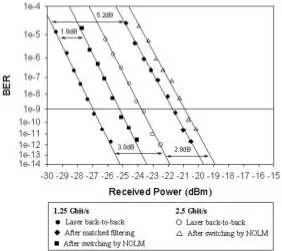
In order to reduce the power penalties observed at both 1.25 and 2.5 Gb/s, we amplified the decoded code-correlation pulse-forms and fed them into the input of the NOLM. The resulting nonlinearly switched pulseforms were then characterized as pre-viously, and BER measurements were performed. The improved pattern recognition contrast is clearly evident when comparing Fig. 9(a) and (b) and Fig. 10(b) and (c). The low-level pedestal obtained with simple matched filtering is almost entirely elim-inated by passage through the NOLM. From Fig. 9, it can also be seen that the shape and duration of the output pulses were restored to values close to the original input laser pulses. The benefits of the pedestal rejection from a system perspective are highlighted in Fig. 11. The previously observed power penal-ties associated with the matched filtering are entirely eliminated. This is true even in the presence of considerable autocorrelation tail overlap at the bit rate of 2.5 Gb/s. Note again that, for both data rates, there was no power penalty associated with trans-mitting the coded bits over the 25-km dispersion-compensated transmission line.
[image:8.612.87.240.329.719.2]Fig. 11. Measured bit error rate (BER) versus received optical power for single-user operation at 1.25 and 2.5 Gb/s.
(a)
(b)
[image:9.612.322.532.373.544.2]Fig. 12. For single-channel operation at 10 Gb/s, (a) eye diagrams (50 ps/div) and (b) BER versus received optical power. The eye diagrams were taken from the 25-km dispersion-compensated transmission experiment described.
Fig. 13. Eye diagrams for two-channel operation at 2.5 Gb/s (100 ps/div). The eye diagrams were taken without transmission experiment, i.e., for the back-to-back case.
instance, we observed an error floor at the 10 BER level after transmission through the dispersion compensated transmission line. Although we have yet to fully establish the cause of this error floor, we do not consider it to be fundamental to the tech-nique itself. We believe it to be more likely associated with the additional loss of the transmission line ( 10 dB) and the specifics of the noise characteristics of the high-power (20 dBm) Er /Yb amplifier used for this particular experiment.
B. Multiuser Operation (Two Channels)
[image:9.612.42.285.375.724.2]Fig. 14. Measured BER versus received optical power for two-channel operation at 1.25 and 2.5 Gb/s.
channel were set to fully overlap temporally at the detector in order to maximize the impact of interchannel interference. As can be seen comparing the eye diagrams in Fig. 13(a) and (b), the temporal overlap of the two orthogonal codes results in severe interference noise at the receiver without the NOLM in place. However, as can be seen in Fig. 13(c), the quality of the eye opening is again drastically improved by nonlinear filtering of the matched filtered signal, resulting in a substantial improvement in the BER performance. The measured BER plots are summarized in Fig. 14. For a data rate of 1.25 Gb/s, error-free operation with a 3.6-dB power penalty reduction relative to simple matched filtering alone is obtained through the use of the NOLM. The residual power penalty of 1.5 dB is comparable to that achieved previously for single-channel operation without the NOLM. We believe that the penalty in the two-channel experiments is due primarily to the contribution to the received average power made by imperfect suppression of the second (orthogonal”) channel. The benefits of using the NOLM at the higher data rate of 2.5 Gb/s are even more manifest. In this instance, it was not possible to get error-free operation without the use of the NOLM. The power penalty relative to the back to back in this instance was 2.8 dB, which, again, was similar to that previously obtained for conventional single-channel operation at this data rate. Note that, as pre-viously discussed, at a data rate of 2.5 Gb/s, the individual pattern recognition signatures overlap, providing an additional element of intrachannel interference noise, and, hence, the slightly increased power penalty relative to the 1.25-Gb/s case, in which no such overlap occurs.
IV. CONCLUSION
We have both numerically and experimentally demonstrated the benefits to be obtained from incorporating a nonlinear
switch (in our case, a NOLM) within SSFBG-based OCDMA and associated all-optical processing and code recognition schemes. Error-free penalty-free operation of a 63-chip 160-Gchip/s OCDMA transmitter–receiver is reliably obtained through the addition of a simple nonlinear optical switch. In our experiments, we used a fiber-based NOLM; however, semiconductor-based nonlinear devices should offer similar system benefits. The improved performance that we have observed at the repetition rate of 10 Gb/s, as well as at both 2.5 and 1.25 Gb/s, offers the possibility of higher capacity data delivery than previously considered viable for coherent direct-sequence OCDMA systems. Moreover, the fact that we have achieved error-free and penalty-free operation in two channel multiplexing experiments implies that the approach should give equivalent system benefits when used in OCDMA systems operating under multiuser operation. We consider these experiments to represent just one example of the sorts of optical processing function that will be enabled by the combination of SSFBG technology and nonlinear optical devices.
REFERENCES
[1] K. Kitayama and N. Wada, “Photonic IP routing,” IEEE Photon. Technol. Lett., vol. 11, pp. 1689–1691, Dec. 1999.
[2] I. Saeki, S. Nishi, and K. Murakami, “All-optical code division mul-tiplexing switching network based on self-routing principle,” IEICE Trans. Commun., vol. E82-B, no. 2, pp. 239–245, 1999.
[3] W. C. Y. Lee, “Overview of cellular CDMA,” IEEE Trans. Veh. Technol., vol. 40, pp. 291–302, Mar. 1991.
[4] P. C. Teh, P. Petropoulos, M. Ibsen, and D. J. Richardson, “The gener-ation, recognition and re-coding of 64-bit, 160 Gbit/s optical code se-quences using superstructured fiber Bragg gratings,” in Proc. 5th Opt-electronics Communication Conf., 2000, PD1-3.
[5] B. J. Eggleton, P. A. Krug, L. Poladian, and F. Ouellette, “Long period superstructure Bragg gratings in optical fibers,” Electron. Lett., vol. 30, pp. 1620–1622, Sept. 15, 1994.
[7] P. Petropoulos, M. Ibsen, M. N. Zervas, and D. J. Richardson, “Gener-ation of a 40-Ghz pulse stream by pulse multiplic“Gener-ation with a sampled fiber Bragg grating,” Opt. Lett., vol. 25, no. 8, pp. 521–523, 2000. [8] P. Petropoulos, M. Ibsen, A. D. Ellis, and D. J. Richardson, “Rectangular
pulse generation based on pulse reshaping using a superstructured fiber Bragg grating,” J. Lightwave Technol., vol. 19, pp. 746–752, May 2001. [9] N. Wada and K. Kitayama, “A 10Gb/s optical code division multiplexing using 8-chip optical bipolar code and coherent detection,” J. Lightwave Technol., vol. 17, pp. 1758–1765, Oct. 1999.
[10] D. B. Hunter and R. A. Minasian, “Programmable high-speed optical code recognition using fiber Bragg grating arrays,” Electron. Lett., vol. 35, pp. 412–414, Mar. 5, 1999.
[11] C.-C. Chang, H. P. Sardesai, and A. M. Weiner, “Code-division multiple-access encoding and decoding of femtosecond optical pulses over a 2.5 km fiber link,” IEEE Photon. Technol. Lett., vol. 10, pp. 171–173, Jan. 1998.
[12] K. P. Jackson, S. A. Newton, B. Moslehi, M. Tur, C. C. Cutler, J. W. Goodman, and H. J. Shaw, “Optical fiber delay-line signal processing,” IEEE Trans. Microwave Theory Tech., vol. MTT-33, no. 3, pp. 193–209, 1985.
[13] P. C. Teh, P. Petropoulos, M. Ibsen, and D. J. Richardson, “A compar-ative study of the performance of seven- and 63–chip optical code-di-vision multiple-access encoders and decoders based on superstructured fiber Bragg gratings,” J. Lightwave Technol., vol. 19, pp. 1352–1365, Sept. 2001.
[14] Z. Zheng, S. Shen, H. P. Sardesai, C. -C. Chang, J. H. Marsh, M. M. Karkhanehchi, and A. M. Weiner, “Ultrafast two-photon absorption op-tical thresholding of spectrally coded pulses,” Opt. Commun., vol. 167, pp. 225–233, 1999.
[15] H. P. Sardesai, C.-C. Chang, and A. M. Weiner, “A femtosecond code-division multiple access communication system test bed,” J. Lightwave Technol., vol. 16, pp. 1953–1964, Nov. 1998.
[16] A. L. Steele, “Pulse compression by an optical fiber loop mirror constructed from two different fibers,” Electron. Lett., vol. 29, pp. 1972–1974, Oct. 28, 1993.
[17] I. Y. Krushchev, I. D. Philips, A. D. Ellis, R. J. Manning, D. Nesset, D. G. Moodie, R. V. Penty, and I. H. White, “OTDM applications of dispersion-imbalanced fiber loop mirror,” Electron. Lett., vol. 35, pp. 1183–1185, July 8, 1999.
[18] D. M. Patrick, A. D. Ellis, and D. M. Spirit, “Bit-rate flexible all-optical demultiplexing using a nonlinear optical loop mirror,” Electron. Lett., vol. 29, pp. 702–703, Apr. 15, 1993.
[19] B.-E. Olsson and P. A. Andrekson, “Noise filtering with the nonlinear optical loop mirror,” J. Lightwave Technol., vol. 13, pp. 213–215, Feb. 1995.
[20] G. P. Agrawal, Nonlinear Fiber Optics. New York: Academic, 1995, pp. 43–55.
[21] L. Chusseau and E. Delevaque, “250-fs optical pulse generation by si-multaneous soliton compression and shaping in a nonlinear optical loop mirror including a weak attenuation,” Opt. Lett., vol. 19, no. 10, pp. 734–736, 1994.
[22] E. H. Dinan and B. Jabbari, “Spreading codes for direct sequence CDMA and wideband CDMA cellular networks,” IEEE Commun. Mag., pp. 48–54, Sept. 1998.
Ju Han Lee received the B.S. and M.S. degrees
in electronics engineering from Seoul National University, Seoul, Korea, in 1995 and 1998, respec-tively. He is currently pursuing the Ph.D. degree in optical communications systems at the University of Southampton, Southampton, U.K.
From 1999 to 2000, he was with Korea Venture Creative Investment, Inc., as an analyst, where he was involved in analysis and investment on telecom-munications technology. In May 2000, he joined the Optoelectronics Research Centre at University of Southampton. His research interests include optical fiber amplifiers (including erbium-doped fiber amplifiers and Raman amplifiers), nonlinear all-optical switching, optical code division multiplexing (OCDM) systems, and optical time division multiplexing (OTDM) systems.
Mr. Lee is a member of the IEEE Lasers and Electro-Optical Society (LEOS) and the Optical Society of America (OSA).
Peh Chiong Teh was born in Perak, Malaysia. He
received the B.Eng. (Hons.) degree from the Depart-ment of Electrical Engineering and Electronics at University of Manchester Institute of Science and Technology (UMIST), Manchester, U.K., in 1999. He is currently pursuing the Ph.D. degree at the Optoelectronics Research Centre (ORC), University of Southampton, Southampton, U.K.
His research interests include the application of su-perstructure fiber Bragg gratings for OCDMA sys-tems, nonlinear optical switching, pulse shaping, and all-optical processing techniques using fiber gratings and optical communica-tions.
Mr. Teh is a member of the IEEE Lasers and Electro-Optics Society (LEOS) and the Optical Society of America (OSA). He received the IEEE Graduate Stu-dent Fellowship Award in 2001.
Periklis Petropoulos graduated from the Department of Electrical Engineering
and Information Technology, University of Patras, Patras, Greece, in 1995. He received the M.Sc. degree in communications engineering from the University of Manchester Institute of Science and Technology (UMIST), Manchester, U.K., in 1995 and the Ph.D. degree in optical telecommunications from the Opto-electronics Research Centre (ORC), University of Southampton, Southampton, U.K., in 2000.
He is currently a Research Fellow with the ORC. His research interests in-clude pulse-shaping applications using superstructured fiber Bragg gratings, optical correlation systems, nonlinear switching, nonlinearities in fibers, and short-pulse fiber lasers.
Dr. Petropoulos is a member of the Optical Society of America (OSA).
Morten Ibsen was born in Copenhagen, Denmark. He was educated in the areas
of physics, mathematics, and optical communications at the Institute of Physics and Astronomy, University of Aarhus, Denmark; the Optical Fibre Technology Centre, University of Sydney, Sydney, Australia; and the Optoelectronic Re-search Centre (ORC), University of Southampton, Southampton, U.K.
His research interests include specialized Bragg grating formation, nonlinear effects in Bragg gratings, devices using Bragg gratings, and application of these in telecommunications systems together with techniques for dispersion compen-sation in optical fibers. In these areas, he has received 12 patients and published more than 200 journal and conference papers. Currently, he leads a group for Bragg gratings research within the ORC.
Mr. Ibsen is a member of the Optical Society of America (OSA) and the In-stitute of Electrcal Engineering (IEE), U.K.
David J. Richardson was born in Southampton, U.K., in 1964. He received the
B.Sc. and Ph.D. degrees from University of Sussex, Brighton, U.K., in 1985 and 1989, respectively.
He is currently Deputy Director of the Optoelectronics Research Centre (ORC), Southampton University, Southampton, U.K., where he holds the Chair in Optoelectronics. His research interests include optical fiber commu-nications, all-optical processing and switching, ultrashort pulse fiber lasers, nonlinear optics, high-power fiber lasers, and the physics and applications of microstructured nonlinear–linear media.