IFAC PapersOnLine 51-2 (2018) 613–618
ScienceDirect
ScienceDirect
2405-8963 © 2018, IFAC (International Federation of Automatic Control) Hosting by Elsevier Ltd. All rights reserved. Peer review under responsibility of International Federation of Automatic Control.
10.1016/j.ifacol.2018.03.104
© 2018, IFAC (International Federation of Automatic Control) Hosting by Elsevier Ltd. All rights reserved.
Towards digital twins through
object-oriented modelling: a machine tool
case study
Bruno Scaglioni∗Gianni Ferretti∗∗
∗School of Electronic and Electrical Engineering, University of Leeds,
Leeds, UK
(e-mail: [email protected])
∗∗Politecnico di Milano, Dipartimento di Elettronica, Informazione e
Bioingegneria, Piazza Leonardo da Vinci 32, 20133, Milano, Italy (e-mail: [email protected])
Abstract: As a basic component for the setup of a digital twin of the working process, the dynamic model of a machine tool, the Mandelli M5, is developed in this paper. The main features of the model are the FEM based description of the structural flexibility of the components of the kinematic structure, the model of the cutting process and the model of the transmission chains and of the control systems. The model has been experimentally validated with respect to the motion dynamic behavior.
Keywords:Object-oriented modelling, machine tools, Industry 4.0, cutting process. 1. INTRODUCTION
The object-oriented modelling approach has been recog-nized for more than a decade as very valuable for virtual prototyping of mechatronic systems (Ferretti et al. (2004)). In particular, Modelica language features like multidomain scope, modular approach, software reuse, efficiency of nu-merical simulation and integration with computer aided design (CAD) tools were recognized as greatly helping the integration of dynamic simulation in the design process, in order to reproduce and analyze the effects of design choices on the overall performance.
In the case of machine tools however, the adoption of the Modelica standard library did not allow to cope in an open and systematic way with two main issues: the modelling of structural flexibility and of working processes. Recently, the results of finite element model (FEM) preprocessing have been integrated in an open library for flexible body modelling (Ferretti et al. (2014a)), while the description of the interaction between the tool and the workpiece must still be addressed case by case, depending on the particular working technology.
Of course, virtual prototyping of mechatronic systems is based on accurate dynamic models and, in this respect, the importance of a thorough model validation cannot be overestimated. This is even more true if the model is used build adigital twin, namely a near-real-time digital image of a physical object or process that helps optimize business performance. It must be pointed out that the digital twin, a key concept in the Industry 4.0 framework, is also based on massive, cumulative, real-time data measurements and on big data analytical capabilities, but it is also true that the role of dynamic models is essential, in particular for performance optimization and predictive maintenance.
As a basic component for the setup of a digital twin of the working process, the dynamic model of a machine tool, the Mandelli M5, is developed in this paper. The main features of the model are the FEM based description of the structural flexibility of the components of the kinematic structure, the model of the cutting process and the model of the transmission chains and of the control systems. As also required in the case of the proper use of digital twins, a set of additional sensors (accelerometers) has been mounted on the machine, allowing an accurate validation of the dynamic behavior. An example of simulation of the machining process has been finally shown.
The paper is organized as follows. Section 2 describes the Mandelli M5 machine tool. Section 3 illustrates the model of the kinematic chains and axes control system. Section 4 describes the model the machine structure and the identification of friction along the sliders of the axis. Section 5 describes the implementation of the model of the cutting forces. Section 6 shows the validation of the dynamic behavior of the model. Section 7 draws some conclusion.
2. MANDELLI M5 MACHINE TOOL
The Mandelli M5 machining center is a CNC machine tool produced by Mandelli Sistemi. The small overall size of the machine allows to reach good stiffness performances with relatively light structures. The machine is characterized by a ”reverse T” structure (Fig. 1) where the Y and Z axes drive the motion of the spindle head, while the X and B axes allow the revolving table to translate and rotate. An hydraulic system compensates for gravity acting along the the vertical Y axis, which however, for the sake of simplicity, has been medelled through a constant force. All the translational axes (X,Y,Z) are driven by recirculating
Copyright © 2018 IFAC 1
Towards digital twins through
object-oriented modelling: a machine tool
case study
Bruno Scaglioni∗Gianni Ferretti∗∗
∗School of Electronic and Electrical Engineering, University of Leeds,
Leeds, UK
(e-mail: [email protected])
∗∗Politecnico di Milano, Dipartimento di Elettronica, Informazione e
Bioingegneria, Piazza Leonardo da Vinci 32, 20133, Milano, Italy (e-mail: [email protected])
Abstract: As a basic component for the setup of a digital twin of the working process, the dynamic model of a machine tool, the Mandelli M5, is developed in this paper. The main features of the model are the FEM based description of the structural flexibility of the components of the kinematic structure, the model of the cutting process and the model of the transmission chains and of the control systems. The model has been experimentally validated with respect to the motion dynamic behavior.
Keywords:Object-oriented modelling, machine tools, Industry 4.0, cutting process. 1. INTRODUCTION
The object-oriented modelling approach has been recog-nized for more than a decade as very valuable for virtual prototyping of mechatronic systems (Ferretti et al. (2004)). In particular, Modelica language features like multidomain scope, modular approach, software reuse, efficiency of nu-merical simulation and integration with computer aided design (CAD) tools were recognized as greatly helping the integration of dynamic simulation in the design process, in order to reproduce and analyze the effects of design choices on the overall performance.
In the case of machine tools however, the adoption of the Modelica standard library did not allow to cope in an open and systematic way with two main issues: the modelling of structural flexibility and of working processes. Recently, the results of finite element model (FEM) preprocessing have been integrated in an open library for flexible body modelling (Ferretti et al. (2014a)), while the description of the interaction between the tool and the workpiece must still be addressed case by case, depending on the particular working technology.
Of course, virtual prototyping of mechatronic systems is based on accurate dynamic models and, in this respect, the importance of a thorough model validation cannot be overestimated. This is even more true if the model is used build adigital twin, namely a near-real-time digital image of a physical object or process that helps optimize business performance. It must be pointed out that the digital twin, a key concept in the Industry 4.0 framework, is also based on massive, cumulative, real-time data measurements and on big data analytical capabilities, but it is also true that the role of dynamic models is essential, in particular for performance optimization and predictive maintenance.
As a basic component for the setup of a digital twin of the working process, the dynamic model of a machine tool, the Mandelli M5, is developed in this paper. The main features of the model are the FEM based description of the structural flexibility of the components of the kinematic structure, the model of the cutting process and the model of the transmission chains and of the control systems. As also required in the case of the proper use of digital twins, a set of additional sensors (accelerometers) has been mounted on the machine, allowing an accurate validation of the dynamic behavior. An example of simulation of the machining process has been finally shown.
The paper is organized as follows. Section 2 describes the Mandelli M5 machine tool. Section 3 illustrates the model of the kinematic chains and axes control system. Section 4 describes the model the machine structure and the identification of friction along the sliders of the axis. Section 5 describes the implementation of the model of the cutting forces. Section 6 shows the validation of the dynamic behavior of the model. Section 7 draws some conclusion.
2. MANDELLI M5 MACHINE TOOL
The Mandelli M5 machining center is a CNC machine tool produced by Mandelli Sistemi. The small overall size of the machine allows to reach good stiffness performances with relatively light structures. The machine is characterized by a ”reverse T” structure (Fig. 1) where the Y and Z axes drive the motion of the spindle head, while the X and B axes allow the revolving table to translate and rotate. An hydraulic system compensates for gravity acting along the the vertical Y axis, which however, for the sake of simplicity, has been medelled through a constant force. All the translational axes (X,Y,Z) are driven by recirculating
Vienna, Austria, February 21-23, 2018
Fig. 1. Axes convention for the M5 machine.
Fig. 2. Workspace of the M5.
ball screws while the sliding motion is supported by linear guidance systems with recirculating balls and preload. The basement is fixed to the ground, a column (or crossbeam) sliding on the base represents the Z axis, and finally the head slides vertically (Y axis) and carries the spindle. In turn, the spindle, equipped with hydrostatic bearings requiring a dedicated control unit and relative actuation systems, is oriented horizontally and together with the turning B axis allows to machine a workpiece on the 4 vertical faces (Fig. 2).
The translational X, Y and Z axes present a common drive chain configuration composed by a SIEMENS 1FT7086-AF7 electric motor connected to the recirculating balls screw through a driving belt. The supports of the screw are flanged on the structural component preceding the axis while the nuts are connected to the moved bodies in a classical way.
The Sinumerik 840D Solution Line numeric control system is installed on this M5 machine, allowing the system to be very flexible and expandable. The control system tuning has been carried out by the machine producer (a detailed description of the Siemens 840D axis control scheme can be found in Parenti (2009)).
Due to the specific research purpose of this machine the control system has been setup in the simplest possible configuration, as such no custom additional filters have been considered. Moreover, only the Y and Z axes have been considered for modelling, as the other axes do not contribute significantly to the overall cutting process dy-namics.
3. MODEL OF THE KINEMATIC CHAINS AND AXES CONTROL SYSTEM
The Modelica model of the kinematic chains is shown in Fig. 3. All axes are driven by a synchronous electric motor
Fig. 3. Modelica scheme of the machine’s axes.
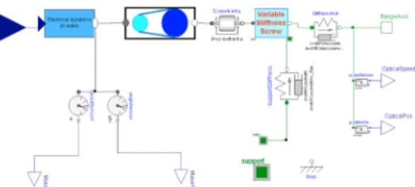
Fig. 4. Scheme of the axis control system.
controlled by an inverter, the overall transmission ratio is defined by the diameters of the driving and driven pulleys, together with the transmission ratio of the screw/nut assemblies. The conversion from rotational to translational motion and the compliances of the components require particular care. The screw can be modelled as a beam with axial compliance however, depending on the position of the nut, the ”active” length of the screw changes and, consequently, the axial stiffness changes.
The electrical dynamics is modeled by means of a second order low-pass filter with a cutting frequency of 2 KHz, while a dedicated component has been developed for the modelling of the pulleys/belt system. In this model, the inertias of the pulleys, the compliance of the belt and the transmission ratio are modelled. As mentioned, the stiffness of the screw depends on the position of the nut. A custom component has been developed in order to trans-form the rotational motion into translation and simulta-neously consider the varying stiffness. In this component, the axial stiffness is computed and a custom spring element is connected in series with a motion conversion element. The model of the axis includes four sensors, the angle and speed sensor on the motor flange represent the encoder, while the sensors on the translational flange represent the optical position sensor placed on the guidance system. The control loops have been modelled as a classical P/PI cascade scheme plus a velocity feed-forward (Parenti (2009)) and the relevant Modelica scheme is shown in Fig. 4. The main components representing the propor-tional controller of the position loop and the PI controller of the velocity loop are highlighted in green, while the feed-forward is contained in the red rectangle, the other components mainly represent unit conversions. It must be pointed out that this scheme allows to assign the same control parameters in the real and simulated machine tool. It must be also recalled that the real numeric control system provides an interpolation layer which allows to smooth the set point input signal of the position loop in order to avoid discontinuous signal and control peaks, this feature is a Siemens industrial secret and there is no chance to implement it in a model directly.
Fig. 1. Axes convention for the M5 machine.
Fig. 2. Workspace of the M5.
ball screws while the sliding motion is supported by linear guidance systems with recirculating balls and preload. The basement is fixed to the ground, a column (or crossbeam) sliding on the base represents the Z axis, and finally the head slides vertically (Y axis) and carries the spindle. In turn, the spindle, equipped with hydrostatic bearings requiring a dedicated control unit and relative actuation systems, is oriented horizontally and together with the turning B axis allows to machine a workpiece on the 4 vertical faces (Fig. 2).
The translational X, Y and Z axes present a common drive chain configuration composed by a SIEMENS 1FT7086-AF7 electric motor connected to the recirculating balls screw through a driving belt. The supports of the screw are flanged on the structural component preceding the axis while the nuts are connected to the moved bodies in a classical way.
The Sinumerik 840D Solution Line numeric control system is installed on this M5 machine, allowing the system to be very flexible and expandable. The control system tuning has been carried out by the machine producer (a detailed description of the Siemens 840D axis control scheme can be found in Parenti (2009)).
Due to the specific research purpose of this machine the control system has been setup in the simplest possible configuration, as such no custom additional filters have been considered. Moreover, only the Y and Z axes have been considered for modelling, as the other axes do not contribute significantly to the overall cutting process dy-namics.
3. MODEL OF THE KINEMATIC CHAINS AND AXES CONTROL SYSTEM
The Modelica model of the kinematic chains is shown in Fig. 3. All axes are driven by a synchronous electric motor
Fig. 3. Modelica scheme of the machine’s axes.
Fig. 4. Scheme of the axis control system.
controlled by an inverter, the overall transmission ratio is defined by the diameters of the driving and driven pulleys, together with the transmission ratio of the screw/nut assemblies. The conversion from rotational to translational motion and the compliances of the components require particular care. The screw can be modelled as a beam with axial compliance however, depending on the position of the nut, the ”active” length of the screw changes and, consequently, the axial stiffness changes.
The electrical dynamics is modeled by means of a second order low-pass filter with a cutting frequency of 2 KHz, while a dedicated component has been developed for the modelling of the pulleys/belt system. In this model, the inertias of the pulleys, the compliance of the belt and the transmission ratio are modelled. As mentioned, the stiffness of the screw depends on the position of the nut. A custom component has been developed in order to trans-form the rotational motion into translation and simulta-neously consider the varying stiffness. In this component, the axial stiffness is computed and a custom spring element is connected in series with a motion conversion element. The model of the axis includes four sensors, the angle and speed sensor on the motor flange represent the encoder, while the sensors on the translational flange represent the optical position sensor placed on the guidance system. The control loops have been modelled as a classical P/PI cascade scheme plus a velocity feed-forward (Parenti (2009)) and the relevant Modelica scheme is shown in Fig. 4. The main components representing the propor-tional controller of the position loop and the PI controller of the velocity loop are highlighted in green, while the feed-forward is contained in the red rectangle, the other components mainly represent unit conversions. It must be pointed out that this scheme allows to assign the same control parameters in the real and simulated machine tool. It must be also recalled that the real numeric control system provides an interpolation layer which allows to smooth the set point input signal of the position loop in order to avoid discontinuous signal and control peaks, this feature is a Siemens industrial secret and there is no chance to implement it in a model directly.
Fig. 5. Modelica model of the flexible structure.
Fig. 6. Side view of the sliders scheme.
4. MODEL OF THE STRUCTURE
The model of the machine’s structure has been developed in two phases. Initially, rigid bodies have been consid-ered and the structural subsystem has been developed accordingly, subsequently, the model has been improved by considering flexible bodies. Figure 5 shows the model of the flexible structure.
The development of the components for the rigid structure is straightforward, separate models for the base, crossbeam and head have been built, and a set of multibody flanges have been added to the components for every connection point. The connection points considered in the models represent the areas where the sliders and the screw/nut mechanisms are flanged on the components.
Particular care has been adopted in modelling the com-pliances of the sliders. Every slider is characterized by a lateral and a radial stiffness, and friction is acting in the direction of motion. In order to model the compliances properly, without introducing planar loops, one transla-tional joint has been introduced for every linear guide to define also custom components describing the stiffness of the sliders in terms of lateral and radial compliance, separated by a fixed translation that represents the dis-tance between the two sliders on every guide. Figure 6 shows a scheme of the side view of the connections: two translational joints are connected to the basement (one for each side) and after every joint two stiffness are placed at a fixed distance and connected to the crossbeam. The same
Fig. 7. Validation experiment for friction coefficients. approach adopted for the basement/crossbeam connection modelling has been followed for the crossbeam/head con-nection.
A specific experiment has been carried out in order to experimentally identify the friction coefficients. The Y and Z axes have been moved with a specific position and ve-locity profile. During the experiment the actuation torque has been logged together with the measured position and velocity. Subsequently, an optimization problem has been set up based on the model:
τtot=τst+µω+Jeqω˙ (1)
where τtot is the total torque, τst is the torque due to
static friction, µ is the dynamic friction coefficient and ω is the angular velocity of the driving screw and Jeq
is the total equivalent inertia of the load, considered as the sum of the term given by rotational components plus the equivalent rotational inertia of the translating mass, converted by means of the transmission ratio. By solving in the minimum square sense the model with respect to the data acquired during the experiment, it has been possible to identify the friction coefficients and the mass of every moving axis. It must be pointed out that these experiments have been performed with no additional load given by workpieces, the mass of a workpiece would have anyway affected the X and B axes, however, this work focuses on the Y and Z axes. The model has been subsequently validated by applying the same coefficients to another simulated position profile and comparing the simulated and measured currents. The comparison is shown in Fig. 7 where the blue line represents the measured current while the green line represents the simulated current. The identified coefficients are reported in Table 1. The rotational inertia resulting from the identification is a good indicator of the validity of results, if properly converted into translational inertia by means of the transmission ratio it should be slightly greater then the mass computed by the CAD model.
Table 1. Identified friction coefficients
Axis Y Z
τst 3.57 Nm 3.87 Nm µ 0.0105 Nms 0.075 Nms Jeq 0.192 Kg/m2 0.0272 Kg/m2
Only the structural flexibilities of the crossbeam and the head have been considered, the compliance of the basement is not negligible but a lumped description, embedded in the sliders compliance, is sufficient to correctly describe its behaviour. Following the procedure described in Ferretti et al. (2014a,b), the FEM model of a flexible body is reduced to a compact, modal description and a record describing the component is imported in a generic flexible body Modelica model. The most critical aspect of the
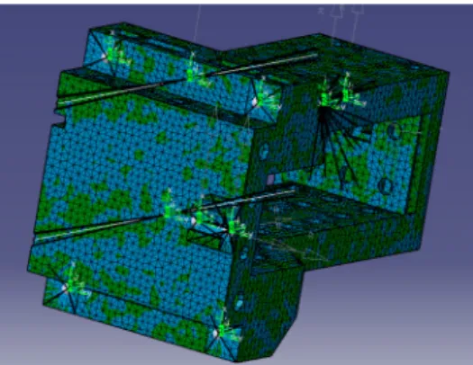
Fig. 8. FEM model of the crossbeam with MPCs.
Fig. 9. Scheme of the cutting process.
pre-processing is the definition of the surfaces where the contact forces are exerted, to this aim, a MPC (Multi Point Constraint) constraint has been created between every connection point and a connection surface. Fig. 8 shows the FEM model of the crossbeam, the highlighted green reference systems represent the MPCs. In order to achieve complete compatibility between flexible and rigid components, the bodies have been wrapped by means of container models, defining external connecting frames (Fig. 5).
5. MODEL OF THE CUTTING PROCESS The model of the cutting forces presented here is based on a model thoroughly discussed in Torta (2013). The model is valid only for complete tool immersion and slot milling process, moreover, the axial forces acting on the tool are neglected. This can be considered as a first step in the introduction of process models within mechatronic modelling, nevertheless, slot milling is the most demanding in terms of torques, energies and machine performances, hence it can be considered as a meaningful test bench. A sketch of the cutting process is shown in Fig. 9. The cutting forces depend on the amount of material removed by theith tooth, and this quantity depends on the position of the tool center and on the path executed by the preceding tool. In particular, the radial and tangential cutting forces for every tooth can be computed as follows: Fr,i(t) =krehi(t) +krchi(t)ba(t) (2)
Ft,i(t) =ktehi(t) +ktchi(t)ba(t) (3)
where Fr,i(t) and Ft,i(t) are the radial and tangential
cutting forces at timet,kre, krc, kteandktcare parameters
depending on the material, hi(t) is the chirp depth and
ba(t) is the depth of every tool pass in the work piece. The
forces on the cartesian axes can then be reconstructed by geometric considerations.
Apparently, the complexity of the model is located in the computation of the chirp depth. This requires to memorize a discretized description of the position of the tool center and to compute the difference from the previous and the current tooth position in time. In fact, the chirp depth can be computed as:
hi(t) = [xi(t)−xi−1(t)]Ix,i(t) + [yi(t)−yi−1(t)]Iy,i(t) (4)
where xi(t), xi−1(t), yi(t) and yi−1(t) are the cartesian
coordinates of the current and previous tooth, andIx,i, Iy,i
are unit vectors describing the principal axes with respect to the current tooth, and can be computed as:
Ix,i= xi(t)−xi−1(t−τ) (xi−x0)2+ (yi−y0)2 (5) Iy,i= yi(t)−yi−1(t−τ) (xi−x0)2+ (yi−y0)2 (6) wherexi, yi are the absolute coordinates of the ith tooth
andx0, y0 are the absolute coordinates of the tool center.
The delay between the teeth depends on the radius of the tool and on the spindle speed and, in the context of the Modelica language, it can easily be handled in the case of both constant and variable spindle speed by the builtin operator delay() which implements a buffer and transparently exposes the delayed value to the user. The computation of the cutting forces is inherently de-scribed by an algorithm, whose inputs are: the current position of the tool center, the position of the tool center in a previous instant (in particular when the previous tooth had the same angular position that the current tooth has at current time), the spindle angle and the material coefficients. The outputs of the algorithm are the Cartesian components of the forces acting on the tool center. The algorithm described above has been implemented in a custom C function, this approach allows to validate the code as a standalone executable and to re-use the same code on various simulation platforms. Subsequently, the code has been wrapped by a Modelica function and embedded into a model containing a Modelica multibody flange. By means of this flange, the forces arising from the cutting process are exerted on the spindle. The X axis of the real machine is actuated by moving the plate holding the workpiece that has not been considered here, hence, in order to correctly consider the feed on the X axis, a real input representing the velocity on X has been added to the component.
The cutting forces model has been validated by compar-ing the results of a benchmark simulation with a Mat-lab/Simulink simulation performed using a model devel-oped by ITIA-CNR (see Torta (2013) for details), obtain-ing identical results. The followobtain-ing values (Table 2 have been assumed for the parameters of the cutting process.
Table 2. Parameters of the cutting process. Number of inserts: 4 Feed direction:X Spindle speed: 800 rpm Tool radius: 40 mm
Depth of cut: 10 mm
Krc4.26×108N/m2 Kre1.11×105N/m
Fig. 8. FEM model of the crossbeam with MPCs.
Fig. 9. Scheme of the cutting process.
pre-processing is the definition of the surfaces where the contact forces are exerted, to this aim, a MPC (Multi Point Constraint) constraint has been created between every connection point and a connection surface. Fig. 8 shows the FEM model of the crossbeam, the highlighted green reference systems represent the MPCs. In order to achieve complete compatibility between flexible and rigid components, the bodies have been wrapped by means of container models, defining external connecting frames (Fig. 5).
5. MODEL OF THE CUTTING PROCESS The model of the cutting forces presented here is based on a model thoroughly discussed in Torta (2013). The model is valid only for complete tool immersion and slot milling process, moreover, the axial forces acting on the tool are neglected. This can be considered as a first step in the introduction of process models within mechatronic modelling, nevertheless, slot milling is the most demanding in terms of torques, energies and machine performances, hence it can be considered as a meaningful test bench. A sketch of the cutting process is shown in Fig. 9. The cutting forces depend on the amount of material removed by theith tooth, and this quantity depends on the position of the tool center and on the path executed by the preceding tool. In particular, the radial and tangential cutting forces for every tooth can be computed as follows: Fr,i(t) =krehi(t) +krchi(t)ba(t) (2)
Ft,i(t) =ktehi(t) +ktchi(t)ba(t) (3)
where Fr,i(t) and Ft,i(t) are the radial and tangential
cutting forces at timet,kre, krc, kteandktcare parameters
depending on the material, hi(t) is the chirp depth and
ba(t) is the depth of every tool pass in the work piece. The
forces on the cartesian axes can then be reconstructed by geometric considerations.
Apparently, the complexity of the model is located in the computation of the chirp depth. This requires to memorize a discretized description of the position of the tool center and to compute the difference from the previous and the current tooth position in time. In fact, the chirp depth can be computed as:
hi(t) = [xi(t)−xi−1(t)]Ix,i(t) + [yi(t)−yi−1(t)]Iy,i(t) (4)
where xi(t), xi−1(t), yi(t) and yi−1(t) are the cartesian
coordinates of the current and previous tooth, andIx,i, Iy,i
are unit vectors describing the principal axes with respect to the current tooth, and can be computed as:
Ix,i= xi(t)−xi−1(t−τ) (xi−x0)2+ (yi−y0)2 (5) Iy,i= yi(t)−yi−1(t−τ) (xi−x0)2+ (yi−y0)2 (6) where xi, yi are the absolute coordinates of the ith tooth
andx0, y0 are the absolute coordinates of the tool center.
The delay between the teeth depends on the radius of the tool and on the spindle speed and, in the context of the Modelica language, it can easily be handled in the case of both constant and variable spindle speed by the builtin operator delay() which implements a buffer and transparently exposes the delayed value to the user. The computation of the cutting forces is inherently de-scribed by an algorithm, whose inputs are: the current position of the tool center, the position of the tool center in a previous instant (in particular when the previous tooth had the same angular position that the current tooth has at current time), the spindle angle and the material coefficients. The outputs of the algorithm are the Cartesian components of the forces acting on the tool center. The algorithm described above has been implemented in a custom C function, this approach allows to validate the code as a standalone executable and to re-use the same code on various simulation platforms. Subsequently, the code has been wrapped by a Modelica function and embedded into a model containing a Modelica multibody flange. By means of this flange, the forces arising from the cutting process are exerted on the spindle. The X axis of the real machine is actuated by moving the plate holding the workpiece that has not been considered here, hence, in order to correctly consider the feed on the X axis, a real input representing the velocity on X has been added to the component.
The cutting forces model has been validated by compar-ing the results of a benchmark simulation with a Mat-lab/Simulink simulation performed using a model devel-oped by ITIA-CNR (see Torta (2013) for details), obtain-ing identical results. The followobtain-ing values (Table 2 have been assumed for the parameters of the cutting process.
Table 2. Parameters of the cutting process. Number of inserts: 4 Feed direction:X Spindle speed: 800 rpm Tool radius: 40 mm
Depth of cut: 10 mm
Krc4.26×108N/m2 Kre1.11×105N/m
Ktc1.65×109 N/m2 Kte9.21×104 N/m
Fig. 10. Initial comparison between Bode diagrams ob-tained from experiments (red) and from the linearized model (blue).
6. EXPERIMENTAL VALIDATION
The experimental validation of the model developed in the previous chapters has been carried out by compari-son between the behaviour of the simulation models and experiments collected on the real machine. This procedure is highly relevant in the overall model development as it allows to test the validity of the model and to acquire sig-nificant awareness on the model sensitivity. In particular, it will be shown how the guidances and sliders stiffness will significantly change with respect to the theoretical values. The validation has been carried out in two ways. At first, an experimental modal analysis has been performed, by exciting the structure with an impulsive force and measur-ing the displacement of particular points on the structure. Then, performances tests provided by the Siemens 840D numeric control system have been carried out on the real machine and the results have been compared with the simulations.
The literature offers many examples (Gagnol et al. (2007); Altintas (2012); Utting and Legeard (2007)) where the experimental modal analysis of a machine tool is per-formed. The displacements are usually measured by means of accelerometers, the acceleration signal is then integrated in time and the frequency content of the signal is extracted. The result of this analysis is a quantitative information of how much a structure is stiff at every frequency.
The procedure described above aims to experimentally reproduce the frequency response of a linear system where the input is a force and the output is a displacement. The excitation force is in fact small enough to consider the system as linear and to identify the eigenmodes of the the structure from the experimental frequency response function. The results of this procedure have been then compared with the analytical linearisation of the model, which can in turn be performed explicitly by means of the
Modelica-Linearsystems2 library. In order to perform such kind of analysis, a dedicated Modelica model has been created, where the inputs and outputs have been explicitly specified. The matrices of the linear system describing the linearized model have been then extracted from the Modelica environment and exported into Matlab in order to compute the Bode diagrams and to compare them with the experimental measurements. Figure 10 shows an initial comparison between the model and the experiment. As it is apparent, the model is statically more rigid and the peaks are misaligned, hence, some tuning is required in order to obtain form the model a similar response with
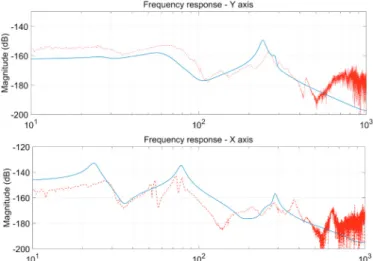
Fig. 11. Comparison between Bode diagrams obtained from experiments (red) and from the linearized model (blue) after model tuning.
respect to the real machine. It must be pointed out that structural stiffness cannot be changed easily and largely depend on the geometry and the material properties of the finite element model, for this reason, the main tuning parameters are the stiffness of the connections. Table 3 shows the tuned values for stiffness and damping, while Fig. 11 shows the frequency responses after the tuning. The diagram of the X axis shows a good correspondence, the peaks of the response are replicated much better after the tuning and the static compliance is correctly com-puted. Regarding the Y axis, a vibration mode involving the sliders is shown at low frequency, while the static stiffness is not correctly reproduced. This phenomenon is caused by the absence of friction in the sliders of the Y axis. On the other hand, the dynamic behaviour at higher frequencies is correctly reproduced.
Table 3. Tuned stiffness and damping of the sliders.
Axis Y Z
Normal Stiffness 3×10⁸N/m 4×10⁸N/m
Lateral stiffness 1.5×10⁸N/m 2.5×10⁸N/m
Damping 12000 Ns/m 8000 Ns/m
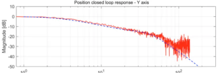
The models of the driving axes and control systems have been validated by means of a similar approach. On the measurements side, the Sinumerik 840D SL numeric con-trol system offers the chance to experimentally identify the frequency response of an axis by exciting the system with a frequency sweep, measuring the axis response in terms of velocity and position and finally computing the response function. This approach allows to analyse the dynamic behaviour of the closed loop system containing the P/PI control scheme as well as the kinematic chain of the driving axis. The measurements carried out by the controller have been compared with the linearised models obtained in Modelica. In Figs. 12 and 13 the closed loop responses of the position and velocity loops are shown. The results are in good accordance but in the case of the velocity loops, the anti-resonance is slightly underestimated. A further tuning phase could reach even better results but a test bench for the axis systems would be required. Moreover,
Fig. 12. Comparison between Bode diagrams of the Y axis position closed loop obtained from experiments (red) and from the linearized model (blue).
Fig. 13. Comparison between Bode diagrams of the Y axis velocity closed loop obtained from experiments (red) and from the linearized model (blue).
Fig. 14. Y - Position of the spindle nose, simulation with cutting forces
the obtained results can already be considered as a good support for the tuning of the axis controllers and the dynamic analysis of the closed loops behaviour. Similar results have been obtained for the Z axis, although not shown here for the sake of brevity.
Finally, in order to show the capabilities of the complete model a simulation of the full machine subject to cutting forces on the tip is reported here. The direction of motion of the workpiece is X, while the cutting forces act on the spindle nose (starting at t = 2). Figs. 14, 15 and 16 show the machine behaviour during the simulation. The red (Fig. 14) and green (Fig. 15) plots represent the Y and X positions of the spindle nose respectively, while the blue plot (Fig. 16) is the torque acting on the Y axis. An interesting behaviour is shown here. The X axis of the machine is actuated on the revolving table, hence the structural part of the machine is not capable of moving on that axis. For this reason, the position of the spindle nose is not controlled on the X axis, as shown by Figure 14. Conversely, the Y axis is actuated, hence the position control loop compensates the displacement, as shown br Figure 15. The slow drift is actually commanded by the control system in order to compensate for the compliance.
7. CONCLUSION
The dynamic model of a machine tool (Mandelli M5)has been developed in this paper, comprehensive of the
de-Fig. 15. X - Position of the spindle nose, simulation with cutting forces
Fig. 16. Torque acting on the Y axis, simulation with cutting forces
scription of the structural flexibility of the components, the model of the cutting process and the model of the transmission chains and of the control systems. Further improvements will consider the modelling of the approach transient of the tool to the workpiece, the validation of the cutting forces (maybe requiring additional sensors, i.e. force/torque sensors) and the adoption of the model to predict a fundamental parameter defining the performance of the working process, namely the regenerative chatter speed.
REFERENCES
Altintas, Y. (2012). Manufacturing Automation: Metal Cutting Mechanics, Machine Tool Vibrations, and CNC Design. Cambridge University Press, 2 edition.
Ferretti, G., Leva, A., and Scaglioni, B. (2014a). Object-oriented modelling of general flexible multibody sys-tems. Mathematical and Computer Modelling of Dy-namical Systems, 20(1), 1–22.
Ferretti, G., Scaglioni, B., and Rossi, A. (2014b). Multi-body model of a motorbike with a flexible swingarm. In Proceedings of the 10th international Modelica Confer-ence, Lund, March 10-12 2014, 273–282.
Ferretti, G., Magnani, G., and Rocco, P. (2004). Virtual prototyping of mechatronic systems.Annual Reviews in Control, 28(2), 193–206.
Gagnol, V., Bouzgarrou, B., Ray, P., and Barra, C. (2007). Model-based chatter stability prediction for high-speed spindles. International Journal of Machine Tools and Manufacture, 47(7-8), 1176–1186.
Parenti, P. (2009). Analisi per la compensazione delle de-formazioni inerziali in una macchina utensile. Master’s thesis, Politecnico di Milano.
Torta, M. (2013).Sviluppo strategie di controllo del chatter rigenerativo in fresatura. Master’s thesis, Politecnico di Milano.
Utting, M. and Legeard, B. (2007). Practical
Model-Based Testing: A Tools Approach. Morgan Kaufmann