Application-Specific 3D Network-on-Chip Design Using Simulated Allocation
∗Pingqiang Zhou
Ping-Hung Yuh
Sachin S. Sapatnekar
Department of Electrical Department of Computer Science Department of Electrical and Computer Engineering and Information Engineering and Computer Engineering
University of Minnesota National Taiwan University University of Minnesota
Minneapolis, MN 55455 Taipei 106, Taiwan Minneapolis, MN 55455
[email protected] [email protected] [email protected]
Abstract— Three-dimensional (3D) silicon integration tech-nologies have provided new opportunities for Network-on-Chip (NoC) architecture design in Systems-on-Chip (SoCs). In this pa-per, we consider the application-specific NoC architecture design problem in a 3D environment. We present an efficient floorplan-aware 3D NoC synthesis algorithm, based on simulated allocation, a stochastic method for traffic flow routing, and accurate power and delay models for NoC components. We demonstrate that this method finds greatly improved topologies for various design ob-jectives such as NoC power (average savings of 34%), network la-tency (average reduction of 35%) and chip temperature (average reduction of 20%).
I. INTRODUCTION
Three dimensional (3D) integrated circuits, in which multi-ple tiers are stacked above each other and vertically intercon-nected using through-silicon vias (TSVs), are emerging as a promising technology for SoCs [1–4]. As compared to 2D de-signs, 3D circuits permit reduced latencies for critical inter-connect structures, resulting in higher system throughput, per-formance, and power, and allow other benefits such as hetero-geneous integration. All of these flexibilities enable the de-sign of new high-performance System-on-Chip (SoC) struc-tures that were previously thought to have prohibitive over-heads. In spite of well-known challenges such as thermal bot-tlenecks (to which several solutions have been proposed), the benefits of 3D integration are considerable. In the context of intrachip communication, 3D technologies have created signif-icant opportunities and challenges in the design of low latency, low power and high bandwidth interconnection networks.
In 2D SoCs choked by interconnect limitations, networks-on-chip (NoCs), composed of switches and links, have been proposed as a scalable solution to the global communication challenges: compared to previous architectures for on-chip communication such as bus-based and point-to-point networks, NoCs have been shown to provide better predictability, lower power consumption and greater scalability [5, 6]. 3D circuits enable the design of more complex and more highly intercon-nected systems: in this context, NoCs promise major benefits, but impose new constraints and limitations. 3D NoC design introduces new issues, such as the technology constraints on the number of TSVs that can be supported, problems related to optimally determining tier assignments and the placement of switches in 3D circuits, and accurate power and delay model-ing issues for 3D interconnects.
This work addresses the problem of designing application-specific 3D NoC architectures for custom SoC designs, in con-junction with floorplanning. Specifically, our work determines both the NoC topology and the floorplan of the NoC switches ∗This work was supported in part by the SRC under contract 2008-TJ-1819.
and cores. We propose a synthesis method to find the best topology for the application, under different optimization ob-jectives such as power and network latency, and determine the paths for traffic flows. We use a 3D thermally-aware floorplan-ner to assign the cores to different 3D tiers, while optimizing chip temperature, and find an initial floorplan for the cores on each tier. Given the positions of cores, we use a stochastic flow allocation method, Simulated Allocation (SAL), to route the traffic flows and build the topology for the application, initially using a simple strategy for determining the approximate loca-tions of the switches. When the best topology is found, a fast floorplanner is applied to further optimize the positions of the added switches. Accurate power and delay models for switches and links are integrated into our algorithm.
Our approach has three significant features that together make it uniquely different from competing approaches: first, we use improved traffic flow routing using SAL that accom-modates a realistic objective function that has components that are nonlinear and/or unavailable in closed form; second, we in-terleave floorplanning with NoC synthesis, using specific mea-sures that encourage convergence by discouraging blocks from moving from their locations in each iteration; and third, we use an accurate NoC delay model that incorporates the effects of queueing delays and network contention.
Our algorithm is extremely flexible and is applicable both to 2D and 3D layouts, but we demonstrate that the use of 3D designs results in significantly reduced NoC power and latency, when compared to optimal 2D implementations.
II. CONTRIBUTIONS OF OURWORK
There has been a great deal of prior work on NoCs alone and on 2D and 3D layout alone, but less on integrating the two. In the area of designing NoC architectures for 3D ICs, most of the literature has focussed on regular 3D NoC topolo-gies such as meshes [7–11], which are appropriate for regu-lar 3D designs [12, 13]. However, most modern SoC architec-tures consist of heterogenous cores such as CPU or DSP mod-ules, video processors, and embedded memory blocks, and the traffic requirements among the cores can vary widely. There-fore, regular topologies such as meshes may have significant area and power overhead [14, 15], and tuning the topology for application-specific solutions can provide immense benefits.
The synthesis of an application-specific NoC topology in-cludes finding the optimal number and size of switches, es-tablishing the connectivity between the switches and with the cores, and finding deadlock-free routing paths for all the traffic flows. For 2D systems, the problem of designing application-specific NoC topologies has been explored by several re-searchers [16–20]. Srinivasanet al.[17] present a three-phase NoC synthesis technique consisting of sequential steps that
floorplan the cores, next perform core-to-router mapping, and then generate the network topology. In [19], Murali et al. present an NoC synthesis method that incorporates the floor-planning process to estimate link power consumption and de-tect timing violations. Several topologies, each with a different number of switches, are explored, starting from one where all the cores are connected to one switch, to one where each core is connected to a separate switch. The traffic flows are ordered so that larger flows are routed first.
In the 3D domain, Yan et al.[14] present an application-specific 3D NoC synthesis algorithm that is based on a rip-up-and-reroute procedure for routing flows, where the traffic flows are ordered in the order of increasing rate requirements so that smaller flows are routed first, followed by a router merg-ing procedure. Muraliet al.[15] propose a 3D NoC topology synthesis algorithm, which is an extension to their previous 2D work [19], described above. The 3D NoC synthesis problem has been shown to be NP-hard in [21].
Our work is motivated by the following observations: • The final results of application-specific NoC topology
synthesis depend on the order in which the traffic flows are routed. In some cases, routing larger flows first pro-vides better results [18, 19], while in others, routing the smaller flows first may yield better results [14]. A strat-egy is required to reduce the dependency of the results on flow ordering.
• In all of the works mentioned previously, the average hop count is used to approximate the average packet latency in NoCs. This ignores the queueing delays in switch ports and the contention among different packets for network resources such as switch ports and physical links, and can-not reflect the impact of physical core-to-switch or switch-to-switch distances on network latency. More accurate de-lay models that include the effects of queueing dede-lay and network contention, and better delay metrics, should be applied for NoC performance analysis.
• The delays and power dissipation for physical links in NoCs are closely linked to the physical floorplan and topology of cores and switches. We show in Section VI that interleaving floorplanning and NoC topology synthe-sis process leads to superior results.
We address these important problems in application-specific NoC topology synthesis. Our solution to overcoming the or-dering problem is based on the use of a multicommodity flow network formulation for the NoC synthesis problem: the ad-vantage of such an approach is that it takes a global view of the problem and eliminates the problem, described above, of find-ing the best order in which to route the traffic flows. The multi-commodity flow problem is a well-known approach for solving such problems, but has seen little use in NoC design, with a few exceptions. In [22, 23], Huet al. propose a scheme to op-timize NoC power consumption through topology exploration and wire style optimization, subject to the average communi-cation latency constraints, but do not handle layout synthesis issues, and assume simple linear objective functions.
Our work utilizes a stochastic SAL approach to efficiently solve the multicommodity flow problem under a nonlinear ob-jective function that can be evaluated by an oracle, but is hard to express in closed form. The SAL framework has previously been used to solve multicommodity flow problems in com-puter network design. We also use an accurate delay model for switches in NoCs which consider the queueing delay and
network contention. Finally, our algorithm performs the floor-planning of cores/switches and NoC topology synthesis in an integrated iterative loop, attempting to find the optimal solution for the problem of application-specific NoC design.
III. PROBLEMINPUTS, OBJECTIVES,ANDCONSTRAINTS The input to our 3D NoC synthesis problem is a directed graph, called the core graph,G(V, E, λ). Each nodevi ∈ V represents a core (either a processing element or a memory unit) and each directed edgeevi,vj ∈E denotes a traffic flow
from sourcevito destinationvj. The bandwidth of traffic flow from corevi tovj is given by λ(evi,vj)inM B/s. In
addi-tion, NoC architectural parameters such as the NoC operating frequency, f , and the data link width, W, are also assumed to be provided as inputs. The operating frequency is usually specified by the design and data link width is dictated by the IP interface standards.
Our 3D NoC synthesis framework permits a variety of ob-jectives and constraints, including considerations that are par-ticularly important in 3D, such as power dissipation, tempera-ture, and the number of TSVs, and NoC-specific issues such as minimizing the average/maximum network latency, limitations on the maximum bandwidth, as well as general factors such as the design area. In addition, the solution must be free of deadlocks, which can occur during routing flows due to cyclic dependencies of resources such as buffers. We use the turn pro-hibition algorithm presented in [24] to ensure that our topology is deadlock-free. The specific optimization objectives in each step of our approach are described in Section IV.
The output of our 3D NoC synthesis solution is an optimized custom deadlock-free network topology with pre-determined paths on the network to route the traffic flows in the core graph and the floorplan of the cores and switches in the NoC such that the constraints are satisfied.
IV. THEOVERALLDESIGNFLOW
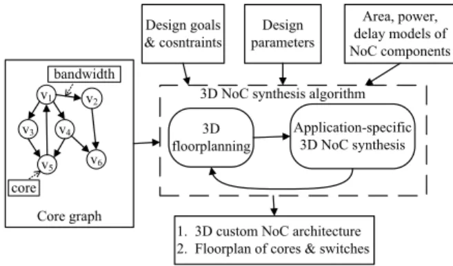
The design flow of our NoC synthesis algorithm is presented in Fig. 1. Given a given a core graph, we first obtain an ini-tial floorplan of the cores using a thermally-aware floorplan-ner. This precedes the 3D NoC synthesis step, and is important because the core locations significantly influence the NoC ar-chitecture. Associating concrete core positions with the NoC synthesis step better enables it to account for link delays and power dissipation. Application-specific 3D NoC synthesis 3D floorplanning Design goals & cosntraints Area, power, delay models of NoC components Design parameters Core graph v1 v4 v3 v2 v5 v6 core bandwidth
1. 3D custom NoC architecture 2. Floorplan of cores & switches
3D NoC synthesis algorithm
Fig. 1.Application-specific 3D NoC synthesis flow.
Our 3D NoC synthesis algorithm is performed on a directed routing graphG′(V′, E′): V′ is the vertex set, which is the union of core set V in the input core graph G(V, E, λ)and the set of added switches,Vs. We assume that the maximum number of switches that can be used in each 3D tierl equals
to the number of cores in that tier, although it is easy to relax this restriction. The edge setE′is constructed as follows: we connect cores in a tierl only to the switches in the same tier
l and adjacent tiersl−1, l+ 1and the switches from all the 3D tiers form a complete graph. A custom NoC topology is a subgraph of the routing graph,G′.
The 3D NoC synthesis problem can be viewed as a multi-commodity flow(MCF) problem. For a core graphG(V, E, λ) and a corresponding routing graph G′(V′, E′) (correspond-ing to a flow network), let c(u, v) be the capacity of edge (u, v)∈E′. The capacityc(u, v)equals to the product of the operating frequencyf and data link widthW. Each commod-ityKi = (si, ti, di), i = 1,· · · , kcorresponds to the weight (traffic flow) along edgeesi,ti in the core graph from source sito destinationti, anddi =λ(esi,ti)is the demand for
com-modity i. Therefore, there are k = |E| commodities in the core graph. Let the flow of commodityialong edge(u, v)be
fi(u, v). Then the MCF problem is to find the optimal assign-ment of flow which satisfies the constraints:
Capacity constraints: ∑ki=1fi(u, v)≤c(u, v) Flow conservation: ∑ω∈V′,u̸=si,tifi(u, ω) = 0 where ∀v, u fi(u, v) =−fi(v, u) Demand satisfaction: ∑ω∈V′fi(si, ω) = ∑ ω∈V′fi(ω, ti) =di Superficially, this idea seems similar to [23], where an MCF formulation is proposed. However, that work is directed to 2D NoC synthesis with a single objective of minimizing NoC power, modeled as a linear function of the flow variables
fi(u, v). The corresponding Linear Programming (LP) prob-lem is solved using an approximation algorithm. Our more general formulation integrates more objectives and more accu-rate modeling for NoC components. In fact, most components of our objective function are nonlinear or, as in case of network latency, unavailable in closed form, rendering an LP-based ap-proach impossible.
We choose to apply an SAL-based flow allocation approach that is particularly suitable for (see Section V-A for details) solving the MCF problems where the objective function is in such a form. The SAL procedure yields the NoC topology and the paths for all the traffic flows in the core graph. In this op-timization, we assume single-path routing for each traffic flow in the core graph, but conceptually, the SAL method can easily be extended to deal with the multipath routing problem.
After the 3D NoC synthesis step, the actual switches and links in the synthesized 3D NoC architecture are fed back to the floorplanner to update the floorplan of the cores and used switches, and the refined floorplan information is used to obtain more accurate power and delay estimates. The process contin-ues iteratively: with the refined floorplan, a new SAL based 3D NoC synthesis procedure is invoked to find a better synthesis solution, and so on.
The specific optimization objectives used in various steps of our approach are as follows:
• For NoC topology construction, we optimize a linear com-bination of the network power, average network latency and TSV count, with constraints on bandwidth.
• For the initial floorplanning step (Section V-C), we op-timize a linear combination of chip temperature and weighted inter-core distance.
• For subsequent steps that floorplan the cores and switches, we optimize a linear combination of design area, link power, link delay and chip temperature.
V. TECHNICAL DETAILS
In this section, we present the major elements in our 3D NoC synthesis algorithm.
A. Simulated Allocation Algorithm
Simulation Allocation (SAL) [25, 26] is a stochastic frame-work for finding near-optimal solutions for the multicommod-ity traffic flow problems. It has been shown to be simpler, but often faster and more efficient, than other stochastic algorithms such as simulated annealing and evolutionary algorithms. The details of the SAL framework used in our work are described in Algorithm 1.
In the core graphG(V, E, λ), let
• Pi be the number of available paths for traffic demand
Ki= (si, ti, di),
• xipbe the amount of traffic flow realizing the trafficKi= (si, ti, di)allocated to pathpin routing graphG′,
• x = {xip : i = 1,2,· · · , k, p = 1,2,· · ·, Pi} be the allocation state,
• |x|=∑i∑pxipbe the total allocated traffic flow, and
• H=∑idibe the total amount of traffic flow.
Note that since we consider single-path routing for each commodity, at mostk paths, one per commodity, will have nonzero flows. Therefore, even though the number of paths can be exponentially large, it is never necessary to enumerate
Pi; storing the allocation statexdoes not impose a significant memory overhead.
Algorithm 1Simulated Allocation (SAL) (adapted from [26]) 1: n= 0;counter= 0;x= 0;Fbest= +∞; 2: repeat 3: ifrandom(0,1)< q(|x|)then 4: allocate(x); 5: else 6: disconnect(x); 7: end if 8: if|x|=Hthen 9: n=n+ 1; 10: counter=counter+ 1; 11: ifF(x)< Fbestthen 12: Fbest=F(x); 13: xbest=x; 14: counter= 0; 15: end if 16: end if 17: untiln=Norcounter=M
The SAL algorithm may start with a given partial allocation state x0 or the with the zero state (xip ≡ 0). In each step, it chooses, with state-dependent probability q(|x|), between allocation(x), i.e., adding the traffic flow for one non-allocated commodity to the current statex, anddisconnect(x), i.e., re-moving the traffic flow for one allocated commodity from cur-rent statex. After a sequence of such moves, from time to time, the algorithm will reach a full allocation state, yielding a feasi-ble solution for the considered profeasi-blem. The procedure termi-nates when the number of visited full allocation states reaches a user-specified limitN or no better solution is found within
Mvisited full allocation states.
Procedureallocation(x) selects one currently non-allocated commodity,Ki= (si, ti, di), at random and allocates it to one
of the allowable paths that have enough residual capacity to support Ki. The path for allocatingKi is chosen to be the minimum cost pathpwith respect to the cost function for the NoC topology construction step. Then we add flowxip = di to the current statexand reduce the capacities of the links on the selected pathpin the routing graph bydi. When routing commodityKi, several new links and switches from the routing graph may be added to the NoC topology and the sizes of the switches on the pathpmay need to be adjusted accordingly.
Procedure disconnect(x) selects an allocated commodity
Ki = (si, ti, di) at random and removes the corresponding flowxip from current statex. We then increase the capacities of the links on the pathpbydi. If some links/switches become unused in the resulting solution, such links/switches are also removed from the NoC topology. The sizes of the switches on the pathpmay need to be adjusted accordingly.
Functionq(γ), defined for0≤γ≤H, has the properties: q(0) = 1 q(H) = 0 1 2 < q(γ)≤1, 0< γ < H According to [26], if q(|x|) =q0> 1 2 for 0< γ < H
then the expected average number of steps (allocations and dis-connections) required to reach a full allocation state starting from statexis no greater than
(H− |x|)/(2q0−1)
For instance, if q0 = 23 then a full allocation state will be
reached from the zero allocation state in only3Hsteps.
B. Analytical Switch Modeling for NoCs
Accurate delay models for switches are required as an in-put to our 3D NoC synthesis problem. We utilize the analyt-ical delay model presented in [27], which includes the effects of queueing delay and network contention. The model con-siders first-come-first-serve input buffered switches and targets wormhole flow control under deterministic routing algorithms. LetSbe the packet size andH the service time for a header flit passing through switchi. The service time of a packet pass-ing through switchi, excluding the queueing delay, is
T =H+S−W
f·W (1)
where W is the data link width and f is the operating fre-quency. For switchi, let
• pbe the total number of ports. • λjbe the traffic arrival rate at portj.
• Njbe the average number of packets in the buffers of in-put portj, andN= [N1, N2, . . . , Np]T.
• cjk be the probability that packets of input ports j and
k compete for the same output port, andCj be the row vectorCj= [cj1, cj2, . . . , cjp].
• Rbe the residual service time seen by the incoming pack-ets, defined as follows: if another packetnis being served when packetmarrives, thenRis the remaining time be-fore packetnleaves the switch.
Then we can write theequilibrium conditionfor the switch as: (I−TΛC)N = Λ ¯R (2) whereΛ = diag{λ1, λ2, . . . , λp}, C = [C1, C2, . . . , Cp]T,
¯
R= ([R, R, . . . , R]1×p)T.
The switch model described by Equation (2) provides a closed form expression for the average number of packets at each input port of the switchi, given the traffic arrival rate (Λ), the packet contention probabilities (C), switch design speci-fications (H, W) and packet size S. For further details, the reader is referred to [27].
C. 3D Floorplanning
An initial step of thermally-aware floorplanning is applied to assign the cores into 3D tiers under thermal considerations, and to optimize the positions of the cores so that highly com-municating cores are placed close to each other. In our im-plementation, we use the 3D thermally-aware floorplanner tool in [28] based on B⋆-tree floorplan model. The floorplanner uses a built-in thermal analysis technique based on the HS3D [28] tool. Of course, any other similar tools can also be integrated into our program.
For each edgeevi,vjwhich connects two cores,viandvj, the
edge weight ofevi,vj is set to be the product of edge bandwidth λ(evi,vj)and the distance dij between vi and vj. Our cost
function is a weighted sum of the chip temperature and the sum of these edge weights. Therefore, we use the floorplanner to find a good initial floorplan of cores that favors our next step of 3D NoC synthesis.
During initial floorplanning, we only consider the commu-nicating cores, since no switches have been introduced at this time. Once a full allocation of traffic flows is found, the topol-ogy of the NoC is determined, including the switches that are used to route traffic. We then invoke the floorplanner to find a refined floorplan of cores and NoC switches, under an objective function that is a linear combination of design area, link power, link delay and chip temperature.
D. Switch Location Estimation and Path Cost Estimation
When routing a flow from sourcesto destinationd, our ob-jective is to find a minimum cost path in the routing graph. While the initial solution considers the physical locations of only the cores, as flow allocation proceeds, new switches will be included in the NoC topology and their physical positions must be estimated to compute the link power and delay.
We estimate the switch locations in the following way: for a newly added switch i, the switch is initially placed at the centroid of the source and destination nodes of switchiin the routing graph. Given these initial estimates of the positions of the newly added switches, we apply Dijkstra’s shortest path al-gorithm on the routing graph to find the minimum cost path for the traffic flow, which is required byallocation(x). When the 3D NoC synthesis step is complete, we feed the actual switches and links in the synthesized architecture to the floorplanner to update the switch locations, for more accurate power and delay estimation. Since the floorplanner is stochastic, it is possible for the new floorplan to be vastly different from the one that was used to generate the NoC topology, negating the assump-tions used to build the topology. To avoid this, we add a penalty to the objective function of the floorplanner to ensure that the blocks do not move far away from their initial locations, and optimize the precise locations of the switches, which were ini-tially placed in (possibly illegal) centroid locations.
VI. EXPERIMENTALRESULTS
A. Experimental Setup
We have implemented3D-SAL-FP, our SAL-based 3D NoC synthesis algorithm with floorplan feedback, in C++. All ex-periments were conducted on an Intel Pentium 4 CPU 3.20GHz machine with 2G memory running Linux.
The design parameters are set as: 900MHz clock frequency, 512-bit packets, 4-flit buffers and 32-bit flits. We use Orion [29] to estimate the power dissipation of the switches. The link power and delay are modeled based on the equations from Pavlidiset al.[8], and the delay of switches are estimated using the model described in Section V-B. All switches and links are evaluated under a 45nm technology.
Several parameters affect the efficiency and performance of the SAL algorithm (Section V-A). In our implementation, we found that a constant function q(γ) = q0, where q0 ∈ [0.75,0.90], can produce good solutions. The user-specified iteration limitN is empirically set to be three times ofk, the number of commodities in the core graph, andM is set to be 50. We find that the best solutions are often obtained withink
full visited allocation states for all the benchmarks.
B. Impact of each strategy applied in our algorithm
Our algorithm3D-SAL-FPimproves upon the previous algo-rithms in [14, 15] by: 1) using a more sophisticated traffic flow routing algorithm (SAL), 2) adding a feedback loop of floor-planning and NoC synthesis to refine the NoC architecture, 3) using a more accurate switch delay model including the effects of queueing delay and network contention. To show the sep-arate impact of these techniques on the NoC design, we have implemented three other 3D NoC synthesis algorithms.
The first algorithm, based on the work by Muraliet al.[15], has two stages: 3D NoC synthesis and floorplanning of the synthesized NoC architecture. At the 3D NoC synthesis stage, simple delay model (average hop count) is used to approximate the average network latency and the traffic flows are routed in fixed order (in the order of decreasing flow rate). In the next stage, we move on to find the floorplan of cores and used switches in the NoC architecture. We refer to this algorithm as the Baseline1 algorithm. The second algorithm differs from Baseline1 in that it applies an improved traffic flow routing strategy (SAL) in the 3D NoC synthesis stage. We refer to this algorithm as theBaseline2algorithm. The third algorithm im-proves uponBaseline2by feeding back the results of floorplan-ning stage to refine the NoC synthesis. The process continues iteratively: after the 3D NoC synthesis step, the actual switches and links in the synthesized solution is fed back to the floor-planner to refine the floorplan of the cores and used switches; with the refined floorplan, a new NoC synthesis procedure is invoked to find a better synthesis solution, and so on. We refer to this algorithm as theBaseline3algorithm. Our3D-SAL-FP differs fromBaseline3in that it use the accurate switch delay model (described in Section V-B ) to incorporate the queueing delay and network contention issues.
We then applied these four algorithms to design 3D applica-tion specific NoC topologies. We compared these algorithms on both a set of existing published benchmarks and several large synthetic 3D benchmarks. Since large standard bench-marks are not available, we use the method proposed in [14] to generate the large synthetic 3D benchmarks. This method is based on the NoC-centric bandwidth version of Rent’s rule proposed by Greenfield et al. [30]. For the small published benchmarks, two 3D tiers are used, where each tier contains one layer of devices and multiple layers of interconnect. For
all of the large synthetic benchmarks, four 3D tiers are used. The corresponding results are shown in Tables I and II. For each algorithm, we report the following: the network power (inmW, including switch power and link power), the average network latency (inns, evaluated by the accurate delay model), the number of TSVs and the maximum chip temperature (in
◦C).
We can observe that using the improved traffic flow rout-ing algorithm, theBaseline2algorithm outperformsBaseline1, achieving 23% power saving for the published benchmarks, 10% reduction in chip temperature and better network perfor-mance. The corresponding numbers for synthetic benchmarks is 21% in power saving and 9% in chip temperature reduction. Furthermore,Baseline3uses the feedback from the floorplan-ning step to improve uponBaseline2, and shows 34% reduc-tion in the power dissipareduc-tion for both published and synthetic benchmarks, about 20% reduction in chip temperature and 10% reduction in average network latency. Finally, with more accu-rate delay model,3D-SAL-FPimproves uponBaseline3, with 26% reduction in average network latency for published bench-marks and 44% for the synthetic benchbench-marks. Since the objec-tive function for these algorithms is a linear combination of several metrics, the use of different sets of weighting factors can result in different Pareto-optimal solutions. For a fair com-parison, we have used identical weighting factors for all four algorithms discussed here. In the solutions shown here, 3D-SAL-FPperforms significantly better thanBaseline3in reduc-ing the delay, and is slightly better on average (and sometimes worse on specific examples) in terms of power and temperature. By altering the weights, other tradeoff points may be identified.
C. Delay and Power Reduction Potential in 3D NoCs
In this section, we further investigate the benefits that 3D cir-cuits can bring to the NoC architecture design. The benchmark B3, with 69 cores and 136 flows, was selected and our 3D-SAL-FPalgorithm was applied to synthesize this benchmark with different numbers of 3D tiers, from 1 to 4.The 1-tier case is the design that uses conventional 2D technology.The results are shown in Table III. For each case, we list the following results: the design footprint, the network power, the maximum path length, the maximum total link delay, the maximum net-work latency, the average netnet-work latency, the total number of TSVs, the maximum chip temperature and the CPU time.
As we can see from Table III, as the number of 3D tiers in-creases, the footprint size continues to decrease, together with the maximum length of the path to route the packets. The re-duced path length further brings down the maximum link de-lay and the total link power at the cost of increased number of TSVs and higher chip temperature. The switch power depends on the specific network traffic and the sizes of the switches de-termined by the customized NoC architectures and does not change much as the number of 3D tiers increases.
VII. CONCLUSION
We have proposed an efficient algorithm, 3D-SAL-FP, to synthesize application-specific 3D NoC architectures. Our al-gorithm utilizes a stochastic approach called simulated alloca-tion to reduce the dependency of NoC design results on flow ordering. We also use accurate delay model for switches in NoCs which consider the queueing delay and network con-tention. Finally, our algorithm performs the floorplanning of cores/switches and NoC topology synthesis in an integrated iterative loop, attempting to find the optimal solution for the problem of application-specific NoC design. Experimental
re-TABLE I
COMPARISON OF THREE ALGORITHMS ON SEVERAL SMALL PUBLISHED BENCHMARKS
Ben Cores Flows Power Baseline1 Baseline2 Baseline3 3D-SAL-FP
Delay # of Tmax Power Delay # of Tmax Power Delay # of Tmax Power Delay # of Tmax
Switch Link Total TSVs Switch Link Total TSVs Switch Link Total TSVs Switch Link Total TSVs
PIP 8 8 54 5 59 3.8 8 66.4 44 4 48 3.7 6 60.6 39 4 43 3.6 7 58.2 38 4 42 3.2 6 55.1 MWD 12 13 94 8 102 4.1 10 72.8 74 7 81 4.0 9 66.5 65 6 71 3.8 12 62.5 65 6 71 3.5 9 62.3 VOPD 12 15 99 11 110 7.3 14 67.8 82 10 92 7.2 7 64.5 73 10 83 6.9 7 59.4 72 9 81 5.1 9 50.9 MEPG4 12 26 165 15 180 10.3 14 70.8 108 15 123 10.1 13 64.7 88 12 100 9.0 14 58.2 90 13 103 6.3 14 59.6 IMP 27 96 612 90 702 9.4 42 78.8 413 99 512 8.0 44 65.2 335 87 422 7.8 42 55.7 346 79 425 6.4 40 56.9 1 1 1 0.77 0.95 0.90 0.66 0.91 0.82 0.66 0.74 0.80 TABLE II
COMPARISON OF THREE ALGORITHMS ON LARGE SYNTHETIC BENCHMARKS
Ben Cores Flows Power Baseline1 Baseline2 Baseline3 3D-SAL-FP
Delay # of Tmax Power Delay # of Tmax Power Delay # of Tmax Power Delay # of Tmax
Switch Link Total TSVs Switch Link Total TSVs Switch Link Total TSVs Switch Link Total TSVs
B1 56 196 1033 291 1324 16.3 119 157.8 956 302 1258 16.0 132 145.4 808 209 1017 15.0 139 128.3 785 214 999 6.7 132 133.2 B2 80 96 783 128 911 7.9 117 133.5 561 118 689 7.9 116 119.6 490 99 589 7.6 124 107.1 494 96 590 4.6 126 107.5 B3 69 136 866 210 1076 13.1 122 150.6 494 243 737 12.0 95 134.4 509 165 674 11.5 105 118.2 504 141 645 9.4 116 118.0 B4 114 396 3128 827 3955 15.9 196 166.4 2230 888 3118 15.5 214 151.6 1826 643 2469 13.9 192 128.6 1721 632 2353 7.3 208 137.0 B5 124 266 1827 848 2675 13.9 254 135.9 1517 686 2203 11.8 264 125.2 1352 432 1784 11.4 256 104.4 1338 468 1806 9.1 241 102.7 1 1 1 0.79 0.94 0.91 0.66 0.89 0.79 0.65 0.56 0.80 TABLE III
COMPARISON OF THE IMPACT OF DIFFERENT NUMBERS OF3DTIERS ONNOCARCHITECTURE DESIGN FOR BENCHMARKB3 LayersFootprint
Network Power Maximum Path Maximum Link Maximum Network Average Network # of
Tmax Time
Switch Link Total Length Delay Latency Latency
TSVs (mm2) (mW) (mW) (mW) (mm) (ns) (ns) (ns) (◦C) (s) 1 216.8 510.5 288.4 798.9 22.1 6.45 14.40 12.42 0 43.8 85.8 2 110.3 505.8 189.2 695.0 17.0 4.95 12.28 9.56 86 63.7 83.9 3 72.0 510.7 164.8 675.5 11.9 3.50 11.51 9.49 94 96.2 87.3 4 56.1 504.8 141.0 645.8 9.2 2.68 11.32 9.44 116 118.0 87.4
sults on a set of benchmarks show that our algorithm can pro-duce greatly improved solutions.
ACKNOWLEDGMENTS
The authors would like to thank professor Yuan Xie in Penn-sylvania State University for providing the 3D floorplanner.
REFERENCES
[1] K. Banerjee, S. J. Souri, P. Kapur, and K. C. Saraswat. 3-D ICs: A novel chip design for improving deep-submicrometer interconnect performance and systems.Proc. IEEE, 89(5), 2001.
[2] L. Xue, C. C. Liu, H.-S. Kim, S. K. Kim, and S. Tiwari. Three-dimensional integration: technology, use, and issues for mixed-signal applications. IEEE Transactions on Electron Devices, 50(3):601–609, Mar. 2003.
[3] W. R. Davis et al. Demystifying 3D ICs: The pros and cons of going vertical. IEEE Design & Test of Computers, 22(6):498–510, Nov.-Dec. 2005.
[4] S. K. Lim. Physical design for 3D system on package. IEEE Design & Test of Computers, 22(6):532–539, Nov.-Dec. 2005.
[5] L. Benini and G. D. Micheli. Networks on chips: A new SoC paradigm.
Computer, 35(1):70–78, 2002.
[6] W. J. Dally and B. Towles. Route packets, not wires: On-chip intecon-nection networks. InProc. DAC, pages 684–689, 2001.
[7] C. Addo-Quaye. Thermal-aware mapping and placement for 3-D NoC designs. InIEEE International SOC Conference, pages 25–28, 2005. [8] V. F. Pavlidis and E. G. Friedman. 3-D topologies for
networks-on-chip. IEEE Transactions on Very Large Scale Integration Systems, 15(10):1081–1090, 2007.
[9] B. Feero and P. P. Pande. Performance evaluation for three-dimensional networks-on-chip. InProc. ISVLSI, pages 305–310, 2007.
[10] J. Kim et al. A novel dimensionally-decomposed router for on-chip com-munication in 3D architectures. InProc. ISCA, pages 138–149, 2007. [11] H. Matsutani, M. Koibuchi, and H. Amano. Tightly-coupled multi-layer
topologies for 3-D NoCs. InICPP, pages 75–75, 2007.
[12] F. Li et al. Design and management of 3D chip multiprocessors using network-in-memory. InProc. ISCA, pages 130–141, 2006.
[13] P. Morrow et al. Design and fabrication of 3D microprocessors. In Ma-terials Research Society Symposium, 2007.
[14] S. Yan and B. Lin. Design of application-specific 3D networks-on-chip architectures. InProc. ICCD, pages 142–149, 2008.
[15] S. Murali, C. Seiculescu, L. Benini, and G. D. Micheli. Synthesis of networks on chips for 3D systems on chips. InProc. ASPDAC, pages 242–247, 2009.
[16] T. Ahonen, H. Bin, and J. Nurmi. Topology optimization for application-specific networks-on-chip. InProc. International Workshop on System Level Interconnect Prediction, pages 53–60, 2004.
[17] K. Srinivasan, K. S. Chatha, and G. Konjevod. An automated technique for topology and route generation of application specific on-chip inter-connection networks. InProc. ICCAD, pages 231–237, 2005.
[18] A. Hansson, K. Goossens, and A. Rˇadulescu. A unified approach to constrained mapping and routing on network-on-chip architectures. In
Proc. CODES-ISSS, pages 75–80, 2005.
[19] S. Murali et al. Designing application-specific networks on chips with floorplan information. InProc. ICCAD, pages 355–362, 2006. [20] S. Yan and B. Lin. Application-specific network-on-chip architecture
synthesis based on set partitions and Steiner trees. InProc. ASPDAC, pages 277–282, 2008.
[21] C. Seiculescu, S. Murali, L. Benini, and G. D. Micheli. SunFloor 3D: A Tool for Networks on Chip Topology Synthesis for 3D Systems on Chip. InProc. DATE, 2009.
[22] Y. Hu, H. Chen, Y. Zhu, A. A. Chien, and C.-K. Cheng. Physical syn-thesis of energy-efficient networks-on-chip through topology exploration and wire style optimizations. InProc. ICCD, pages 111–118, 2005. [23] Y. Hu, Y. Zhu, H. Chen, R. Graham, and C.-K. Cheng. Communication
latency aware low power NoC synthesis. InProc. DAC, pages 574–579, 2006.
[24] D. S. Mark, M. Karpovsky, and L. Zakrevski. Application of network calculus to general topologies using turn-prohibition.IEEE/ACM Trans-actions on Networking, 11(3):411–421, 2003.
[25] M. Pi´oro and P. Gajowniczek. Solving multi commodity integral flow problems by simulated allocation. Telecommunication Systems, 7(1-3):17–28, 1997.
[26] M. Pi´oro and D. Medhi. Routing, Flow, and Capacity Design in Com-munication and Computer Networks. Morgan Kaufmann Publishers Inc., San Francisco, CA, USA, 2004.
[27] U. Y. Ogras and R. Marculescu. Analytical router modeling for networks-on-chip performance analysis. InProc. DATE, pages 1096 – 1101, 2007. [28] W.-L. Hung, G. M. Link, Yuan Xie, N. Vijaykrishnan, and M. J. Irwin. Interconnect and thermal-aware floorplanning for 3D microprocessors. InProc. ISQED, pages 98–104, 2006.
[29] H. Wang, X. Zhu, L.-S. Peh, and S. Malik. Orion: A power-performance simulator for interconnection networks. InMICRO 35, pages 294–305, 2002.
[30] D. Greenfield, A. Banerjee, J.-G. Lee, and S. Moore. Implications of Rent’s Rule for NoC design and its fault-tolerance. InProc. NOCS, pages 283–294, 2007.