Flight Data Recorder Read-Out
Technical and Regulatory Aspects
ÉQUIPEMENT, DU TOURISME ET DE LA MER – BUREAU
D’ENQUETES ET D’ANALYSES POUR LA SECURITE DE L’AVI
ATION CIVILE
Table of Contents
GLOSSARY ...4
SCOPE...5
1 - TECHNICAL ASPECTS...6
1.1 Technical Evolution of FDRs...6
1.1.1 Metal foil and photographic film recorders ...6
1.1.2 Magnetic Tape Recorders...6
1.1.3 Acquisition unit...7
1.1.4 Solid state recorders ...7
1.1.5 Non-protected recorders ...8
1.2 Data Acquisition System...9
1.2.1 Data acquisition computer operational concept ...9
1.2.2 Data Frame Layout ...9
1.2.3 Parameter decoding...9
1.3 Recording System Operational Check ... 10
1.3.1 Verification of recorded parameters...10
1.3.2 Calibration of measuring and processing channels...11
2 - OPERATIONAL AND REGULATORY ASPECTS...14
2.1 Overview of Regulations... 14
2.1.1 Introduction ...14
2.1.2 Annex 6, Part I ...14
2.1.3 JAR OPS 1 and OPS 1 ...17
2.1.4 French texts ...18
2.1.5 Information on US regulations ...19
2.2 Comparison of regulatory requirements ... 20
2.2.1 Programme for analysis of recorded parameters...20
2.2.2 Inspection of FDR systems ...20
2.2.3 Calibration of measuring and processing channels... 21
2.2.4 Documentation within operators area of responsibility...22
2.3 Problems encountered during FDR operations... 23
2.3.1 Missing or incomplete data ...23
2.3.2 Incomplete or unavailable data frame layout documents ...24
2.4 Survey of 20 French Airlines ... 28
2.4.1 Airline participation...28
2.4.2 FDR maintenance ...28
2.4.3 Lessons Learned programme and flight data analysis...28
2.4.4 Data frame layout documents ...29
2.4.5 Measuring and processing channel calibration ...30
2.4.6 Summary ...30
3 - CONCLUSIONS...32
4 - SAFETY RECOMMENDATIONS...33
4.1 Installation of FDRs on Aircraft... 33
4.2 Data Frame Layout Documents ... 34
4.3 Recording Quality... 34
4.4 Verification of Recorded Parameters... 35
4.5 Calibration of measuring and processing channels... 36
Glossary
AMC Acceptable Means of Conformity ARINC Aeronautical Radio Incorporated BCD Binary Coded Decimal
CAA Civil Aviation Authority (United Kingdom) CASA Civil Aviation Safety Authority (Australia) CVR Cockpit Voice Recorder
DAC Direction de l’Aviation Civile (France) DAR Direct Access Recorder
DFL Data Frame Layout
DGAC Direction Générale de l’Aviation Civile (France) DMU Data Management Unit
EASA European Aviation Safety Agency
ED EUROCAE Document
EGT Exhaust Gas Temperature
EUROCAE European Organization for Civil Aviation Equipment FAA Federal Aviation Administration (USA)
FAR Federal Aviation Regulations FDAU Flight Data Acquisition Unit FDR Flight Data Recorder
GPWS Ground Proximity Warning System IRS Inertial Reference System
JAA Joint Aviation Authorities
JAR Joint Airworthiness Requirements
kt Knot
QAR Quick Access Recorder
ICAO International Civil Aviation Organization
MOPS Minimum Operational Performance Specifications NTSB National Transportation Safety Board (USA)
SFACT Service de la Formation Aéronautique et du Contrôle Technique (France)
SSCVR Solid State Cockpit Voice Recorder SSFDR Solid State Flight Data Recorder
SCOPE
The readout of Flight Data Recorders (FDR), whether performed in France or elsewhere, often brings to light a variety of problems such as aircraft operators having incomplete, outdated or inappropriate documents or not having the relevant documentation at all. Sometimes this significantly delays the validation of the readout work.
However, rapidly obtaining complete and accurate data after an accident or an incident is often critical for the technical investigation and, in a broader way, to air transport safety. Data extracted from FDRs help to determine causes and to develop appropriate preventive measures.
There are no single guideline document relating to FDR regulations. Several international and French texts touch on these aspects, though not always in a coherent fashion.
In order to get a complete picture of the problems encountered, the BEA has produced this study, based on the analysis of known issues and on consultations with French aircraft operators. Its objective is to increase awareness among the various actors of the importance of FDRs for accident prevention and to recommend improvements.
1 - TECHNICAL ASPECTS
Flight recorders, often called “black boxes” by the media are two devices designed to record data about flights. Flight Data Recorders (FDR) record various flight parameters, whereas Cockpit Voice Recorders (CVR) record the acoustic environment of cockpits. This study will be limited to FDRs.
1.1 Technical Evolution of FDRs
The aeronautical industry’s efforts to design recording devices that could sustain accidental damage, such as impact and fire, date to the beginning of commercial aviation. It was only in 1958 that aviation authorities began imposing minimum specifications for flight recorders to aid technical investigations.
1.1.1 Metal foil and photographic film recorders
Boeing 707’s, DC8’s and Caravelles were the first jet engine aircraft to be equipped with FDRs in the early sixties. These recorders consisted of a mechanical stylus engraving a metal foil. For metal foil FDRs, the parameters are processed internally with data coming in directly from basic aircraft sensors, such as accelerometers and pitot tubes. At about the same time, a similar technology consisted of replacing the sheet of metal with a photographic film and the mechanical stylus with light beams. That was the photographic film FDR. Both types of FDRs could only monitor a limited number of important parameters, usually 5 or 6, such as magnetic heading and airspeed.
Inside a metal foil recorder
1.1.2 Magnetic Tape Recorders
Metal foil and photographic film FDRs started to fall behind in relation to investigation needs in 1965. With the introduction of magnetic tape-based recorders, it became possible to not only record conversations but also to progressively increase the number of parameters monitored by FDRs.
Stylus
With the new magnetic FDRs, parameters were no longer recorded in a single stream. Instead, they were first sampled, digitalized and multiplexed inside a 1-second long frame. Then, this digital frame was recorded on a magnetic tape using simple signals to code 0’s and 1’s. Hence the name Digital Flight Data Recorder (DFDR).
Inside a magnetic tape recorder 1.1.3 Acquisition unit
As the need for more parameters grew and as new digital technology appeared, it became inadequate to have FDRs compute parameters internally based on data received from sensors.
Flight data acquisition devices began to be designed to collect all parameters before being recorded. These devices include the Flight Data Acquisition Unit (FDAU), Flight Data Interface Unit (FDIU) or Flight Data Acquisition Card (FDAC). They order data and then send it to FDRs, whose function is then limited to data recording.
Note: Aircraft operators can modify FDAU programming.
It is important to note that mainly large aircraft in the public transport category are equipped with data acquisition units. For smaller aircraft, the data acquisition function is still often performed by FDRs.
1.1.4 Solid state recorders
With the evolution of digital technologies, solid-state memory cards replaced magnetic tapes in FDRs around 1985. Recordings on these new Solid State Flight Data Recorders (SSFDR) have far better restitution reliability than on the magnetic FDRs.
As memory cards got smaller, the number of recorded parameters went up to several hundred, sampling frequencies increased and recording times of some models rose to 50 hours or more.
Sound recorders also benefited from this technological evolution, with not only the possibility of recording sound digitally, but also with a recording time that was extended to 2 hours as opposed to half an hour for magnetic tape-based CVRs.
Memory Card on an SSFDR
1.1.5 Non-protected recorders
The introduction of data acquisition units has also benefited what is commonly called “flight data monitoring”. FDRs were the only devices recording data and that data was only used after an accident. Now, with data acquisition units, data is also directed to other types of recorders.
These recorders are not protected. The recording media can be a tape, an optical magnetic disc or a PCMCIA card. The recording media is designed to be removed and replaced quickly. The access to the recording media is located either in the cockpit or in the electronics bay.
Quick Access Recorders (QAR’s) usually record exactly the same data as FDRs. Onboard an aircraft, the data acquisition unit feeds both the FDR and the QAR. The most recent QARs also have input ports compatible with the standard aircraft buses (ARINC 429) and can therefore receive additional data.
Direct Access Recorders (DARs) receive data from Data Management Units (DMUs) and can be programmed not only to select which parameters to record and with which sampling frequency, but also to select the recording mode: periodic recording or recording triggered by events such as a parameter passing over a pre-determined threshold.
These recorders are used for maintenance, research or flight data monitoring purposes.
1.2 Data Acquisition System
1.2.1 Data acquisition computer operational concept
Data acquisition computers centralize and format data coming from sensors, onboard computers and other instruments and then transfer it to FDRs via a dedicated digital link (serial link ARINC 573 or 717). There are four types of input data:
• Discrete (logical status detection, indicators, switches, relays);
• Analog (potentiometer);
• Synchronization transmitters;
• Digital bus (ARINC 429).
Data acquisition units are programmed to produce a continual flow of data towards FDRs. They deal with the time sampling of parameters and of their digital encoding from the actual physical value to the recorded value.
1.2.2 Data Frame Layout
FDR Data Frame Layout (DFL) documents depend on the type of recording systems. They describe:
• the programming method used by the data acquisition system (location of parameters, number of bits used to encode parameters, type and method of encoding);
• the functions used to convert the recorded value into the actual physical value. For each parameter, the conversion function is checked with the calibration of the measuring and processing channel, as mentioned later in this document. These documents are completed by calibration control reports on the mandatory parameters.
1.2.3 Parameter decoding
Data acquisition systems output a binary file sequenced in four-second frames. Each frame is divided into four one-second-subframes.
Each subframe is divided into 64, 128, 256 or 512 “words” of 12 bits each, depending on the FDR’s technology. The bit is the basic binary unit whose value is either 0 or 1.
Parameter: AIRSPEED
Word(s): 19 Bits: 12-1 Rate: 1 sps Subframe: All
CONVERSION FACTOR
VALUES DECIMAL ENG. UNITS
MINIMUM 0 0 kt
NEUTRAL / MID POINT 2 047 512 kt
MAXIMUM 4 095 1 024 kt
ENGINEERING UNITS CONVERSION EQUATION: LINEAR
Y = A0 + A1* X Where: Y = Output in Engineering Units
X = Input in Decimal
A0= 0.0 A1= 0.25006
(1) Coding a binary value on 12 bits from 000000000000 to 111111111111 is equivalent to a
decimal coding from 0 to 212-1, or from 0 to 4095. (2) Sps: sample per second.
Data frame layout for AIRSPEED
1.3 Recording System Operational Check
The check on recorded parameters and the calibration check on measuring and processing channels are complementary maintenance tasks that improve the quality of recordings.
1.3.1 Verification of recorded parameters
1.3.1.1 Objective
The evaluation of the recording system’s general operation and of the quality of data frame layout documents is performed through the check on recorded parameters in FDRs.
The parameter is recorded on word #19
Raw data has a value ranging from 0 to 4095 and must be converted into an engineering value for AIRSPEED (kt)
The parameter is recorded on every subframe The parameter is recorded
1 time per second (2)
The parameter is coded on 12 bits (1)
The raw value to engineering value conversion is linear and transforms a binary value ranging from 0 to 4095 into an airspeed ranging from 0 to 1024 kts. The equation is: Y (kt) = 0.25006*X
1.3.1.2 Method
In order to be efficient, the check must only deal with recordings on FDRs and not on other devices like QARs or DARs. The entire set of recorded data can be copied for analysis and be converted into engineering units (1) using decoding
software that has to be programmed according to data frame layout documents. The check on recorded parameters may include:
• location of regulatory parameters in accordance with data frame layouts;
• validity of conversion functions for each regulatory parameter, taking into account their operational value range;
• coherence of parameters’ patterns for several phases of flight;
• check for long or cyclical areas of unreadable data;
• chronological integrity of recordings.
Examples of procedures are available in the Flight Data Recorder Maintenance
document published by Australian authorities (2).
1.3.2 Calibration of measuring and processing channels
1.3.2.1 Objective
Data recording quality is evaluated by comparing a parameter’s value, as measured by instruments, with the recorded value. It is therefore essential to calibrate the measuring and processing channels of each parameter.
Calibration is also necessary because conversion functions provided by manufacturers are only theoretical since they are the results of tests performed on prototypes, and can therefore differ from the ones of the actual aircraft.
In addition, several factors can alter the quality of the measurements. These factors include:
• Sensor aging. Sensors are subject to environmental constraints like water or high temperature and pressure variations that can cause the system to drift from the initial calibration.
• Connecting an additional device to an analog input, like a potentiometer or a synchronized transmitter. These additions can modify the electrical characteristics of the transmitted signal in terms of amplitude and/or phase.
• The disassembly and reassembly of mechanical elements. This can cause some sensors to go out of adjustment and can happen during major overhauls or during an FDR systems retrofit.
(1) An engineering unit is a unit measuring a physical value. For instance, for pressure altitude, the
engineering unit is the foot.
(2) Civil Aviation Safety Authority Australia, October 2002, Flight Data Recorder Maintenance
Finally, sensors used for recorders can be different from the ones feeding data to flight instruments and other aircraft systems. Consequently, a recorded value can differ from the value actually used by aircraft systems.
Note: These problems primarily affect older aircraft. For more recent ones, parameters are usually digitized and used by several systems, including flight data acquisition systems, which makes anomaly detection easier.
When allowable deviations between nominal values and recorded values are exceeded, two types of actions can be taken, depending on the nature of the issue:
• replacement or repair of malfunctioning elements, or
• modification of conversion functions in data frame layout documents, through a calibration procedure.
Discrete parameters which are used to warn of unusual situations, such as GPWS Warning, Stick Shaker, Mach Warning, and/or Engine Fire, are not activated during normal flights and do not appear on FDR recordings. Examining these recordings is therefore not adequate to ensure that the recording of these alarm parameters is performed properly. The following procedure suits this need better. 1.3.2.2 Calibration procedure
Calibration of the parameters’ measuring and processing channels consists of generating baseline values, entering them into sensors and noting the output values of acquisition devices, or, in the case where the acquisition is performed by the recorders, retrieving the corresponding recorded value.
Calibration process diagram FDR
FDAU Sensor Computation of the parameter
by the measuring and processing channel
Value coded and digitalized by the FDAU Numerical value recorded by the FDR The FDAU’s programming specifies
the location of each parameter inside the recorded data stream Calibration of the
system consists of comparing the sensors’ input value to
the numerical value outputted by the FDAU
1.3.2.2.1 Generation of baseline values
Baseline values can be generated using one of the following methods:
• Sensor activation. This includes:
o Sensor “stimulation” which consists of applying physical inputs to it, such as a calibrated pressure on a static port;
o Sensor “simulation” which consists of reproducing the sensor’s electrical signal output. This is done when sensor stimulation is too complex to perform, as for instance for engine temperature or alarms.
• Activation of auto-test functions of systems such as Inertial Reference Systems (IRS). These functions internally adjust parameters with reference to baselines.
• Read-out of instrument indications when no internal test exists or when sensors feeding the recording system also feed cockpit indicators.
1.3.2.2.2 Check on output values
In order to check the output values of the data acquisition system, a compatible read-out system can be connected to it. This read-out system computes the parameters’ real-time values using conversion functions identical to those given by the data frame layout document.
1.3.2.2.3 Example
Calibration of the “aileron position” parameter Actual position
measured with a clinometer (degrees)
Raw output value from the
acquisition system
Converted value using conversion functions (degrees) Deviation of the acquisition system (degrees) + 25.5 (right stop) 2,880 + 25.2 - 0.3 + 15 2,545 + 15.1 + 0.1 0 2,065 0.5 + 0.5 - 15 1,603 - 13.4 + 1.6 - 25 (left stop) 1,246 - 24.3 + 0.7
Maximum allowable deviation: +/- 2°
Source: AMC OPS 1.720 1.725 Appendix 1 – Table A
Result: precision OK
As of today, the calibration of all measuring and processing channels is only performed by aircraft manufacturers prior to delivery.
2 - OPERATIONAL AND REGULATORY ASPECTS
2.1 Overview of Regulations
2.1.1 Introduction
Regulations pertaining to flight data recorders and data frame layouts are covered by several different texts. At the ICAO level, Annex 6 (eighth Edition, July 2001) and Annex 13 are the principal documents relating to these subjects. At the European level, information can be found in the JAR OPS1 document, which, at the French level, was transposed into a regulation dated 12 May 1997 (called OPS1).
EUROCAE also produces documents regarding recorders. These documents are referred to by a variety of other regulations. See Appendices for extracts from EUROCAE 55 (ED55) and EUROCAE 112 (ED112).
2.1.2 Annex 6, Part I
Annex 6 to the Convention on International Civil Aviation contains standards and recommended practices for the technical operation of aircraft. It is divided into 3 parts. Part I contains standards and recommended practices applicable to the operation of aircraft by operators authorized to conduct international commercial air transport operations. Provisions relating to flight recorders are included in attachment D.
2.1.2.1 FDR equipment regulations
Annex 6, Part I, paragraphs 6.3.3 and 6.3.4 indicate that all aircraft with a maximum certificated take-off weight over 5,700 kg are required to be equipped with an FDR, regardless of the date of the individual certificate of airworthiness. Paragraph 6.3.6 indicates that the list of parameters (3) to be recorded for aircraft
with a maximum certificated take-off weight of over 27,000 kg also applies to aircraft with a maximum certificated take-off weight of over 5,700 kg and for which the individual certificate of airworthiness was first issued after 1 January 2005. France has pointed out that the list of parameters required by ICAO Annex 6 has not been incorporated into French regulations. Consequently, the standard described in paragraph 6.3.6 has not yet been applied by France.
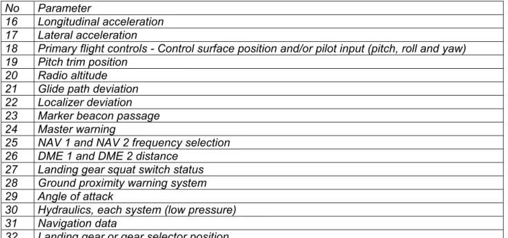
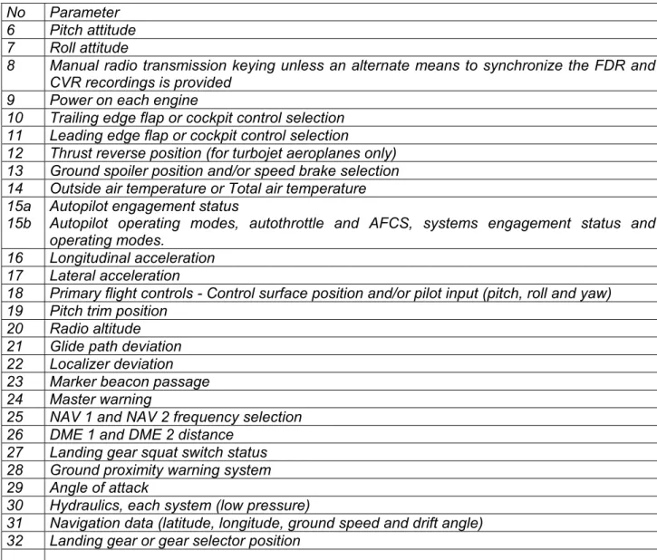
See Appendix III for compulsory parameter requirements.
2.1.2.2 Installation of FDRs
Attachment D to ICAO Annex 6, paragraph 1.3 lists the rules relative to the installation of FDRs. It includes:
• Recording requirements on installed equipment must be verified by methods approved by the appropriate certifying authority.
• The manufacturer must provide the national certifying authority with the following information concerning the FDR:
o manufacturer’s operating instructions and installation procedures,
o parameter origin or source and equations which relate to conversions to units of measurement,
o Manufacturer’s test reports.
Operators must archive all documents concerning FDRs (4) in case they need to be
read out. Annex 6, Attachment D, paragraph 1.3.4 states:
“Documentation concerning parameter allocation, conversion equations, periodic calibration and other serviceability/maintenance information should be sufficient to ensure that accident investigation authorities have the necessary information to read out the data in engineering units.”
2.1.2.3 Flight data analysis programme Paragraph 3.2.3 states that:
“From 1 January 2005, an operator of an aeroplane of a maximum certificated take-off mass in excess of 27,000 kg shall establish and maintain a flight data analysis programme as part of its prevention and flight safety programme.
Note: an operator may sub-contract performance of a flight data analysis programme to another party while retaining overall responsibility for the programme”.
A note in paragraph 3.2.4 states that:
“Guidance on flight data analysis is contained in the Accident Prevention Manual
(Doc 9422)”.
France has specified that such an analysis programme is required by French regulations for aircraft with a certificated take-off weight in excess of 10,000 kg or with a number of seats in maximum configuration in excess of 20.
(4) This information is usually listed in documents called “data frame layout documents” in this
2.1.2.4 Inspection of FDR systems
ICAO Annex 6, Part I, Attachment D, paragraph 3.2 states that annual inspection of FDRs should be carried out by operators as follows:
• “the read-out of the recorded data from the FDR (…) should ensure that the recorder operates correctly for the nominal duration of the recording;”
• “the analysis of the FDR should evaluate the quality of the recorded data to (…) determine the nature and distribution of the errors;”
• “the FDR data from a complete flight should be examined in engineering units to evaluate the validity of all recorded parameters (…)”. Thus, the engineered parameters processed from raw data must be examined.
• “Particular attention should be given to parameters from sensors dedicated to the FDR”, because failures of these sensors cannot be detected by other onboard systems.
• “the read-out facility should have the necessary software to accurately convert the recorded values to engineering units and to determine the status of discrete signals”. The use of software for these tasks is necessary in order to process all the compulsory parameters of a flight in a timely manner.
• “A report of the annual inspection should be made available on request to the State’s regulatory authority for monitoring purposes”.
2.1.2.5 Criteria for serviceability of flight recorder systems
Attachment D, paragraph 3.3 states that:
“Flight recorder systems should be considered unserviceable if there is a significant period of poor quality data (…), or if one or more of the mandatory parameters is not recorded correctly.“
Corrective actions must be taken on the flight recorder system as soon as a mandatory parameter is not recorded in the manner specified by quality requirements.
2.1.2.6 Calibration of measuring and processing channels
Attachment D, paragraph 3.5 indicates the frequency at which the recorder system and the measuring and processing channel should be re-calibrated:
• “the FDR system should be re-calibrated at least every five years […] for the mandatory parameters”
• when the parameters of altitude and airspeed are provided by sensors that are dedicated to the FDR system, there should be a re-calibration performed as recommended by the sensor manufacturer, at least every two years.
2.1.3 JAR OPS 1 and OPS 1
2.1.3.1 FDR regulations and nature of data to be recorded
JAR OPS 1 application depends on the date of the individual certificate of airworthiness (5). Paragraphs 1.715, 1.720 and 1.725 for FDRs and paragraph
1.727 for Combination Recorders describe how recorders have to be installed, the parameters to record and the length of recordings.
It is specified that aircraft with a maximum certified take-off weight over 5,700 kg are required to be equipped with an FDR. This requirement is extended to multi-engine turbine powered aircraft, which have a maximum approved passenger seating configuration of more than 9, when the individual certificate of airworthiness was issued after 1 April 1998.
Parameters to be recorded are listed in JAR OPS 1 (see Appendix III of this study) which stipulates that a method to extract data from the memory support must be available. However, not all parameters are required to be recorded, depending on the maximum certificated take-off weight and on the date of issue of the individual certificate of airworthiness.
Operators must comply, when possible, with operational calibration, precision and resolution specifications defined in ED55. See Appendix I for an extract from these specifications.
2.1.3.2 Flight safety programme
Paragraphs 1.037 of JAR OPS 1 and the French regulation of 12 May 1997 have the same title, “Accident Prevention and Flight Safety Programme”, but their contents slightly differ.
Paragraph 1.037 of the French regulation states, “an operator shall establish an accident prevention and flight safety programme which includes an analysis of flight safety or flight parameter recording reports.” This requirement was put in place in response to recommendations after the accident that occurred on 20 January 1992 near Mont Sainte-Odile (6).
(5) Effective dates :
-OPS 1.715: aircraft for which the individual certificate of airworthiness was issued after 1 April 1998 -OPS 1.720: aircraft for which the individual certificate of airworthiness was issued between 1 June 1990 and 31 March 1998
-OPS 1.725: aircraft for which the individual certificate of airworthiness was issued before 1 June 1990
(6) In the accident report involving an Airbus A320 registered F-GGED that crashed on 20 January
1992 near Mont Sainte-Odile in Alsace, France, domestic and international civil aviation authorities were recommended to take measures to encourage aircraft operators:
-to expand their systematic analysis of recorded flight parameters,
-to perform a detailed analysis, including on an operational level, of the major detected anomalies by a specialized department at the operator,
-to communicate, using appropriate means, the results of analyses to the appropriate authorities, manufacturers and other operators, while complying with confidentiality and anonymity constraints.
Since 1 January 2000, flight safety reports and flight parameter recordings must be analyzed for turbine-engine-powered aircraft with a maximum certificated take-off weight in excess of 10,000 kg or with a number of seats, in maximum configuration, in excess of 20.
In contrast, JAR OPS 1, paragraph 1.037 requires since 1 January 2005 a flight data monitoring programme for those aeroplanes with a maximum certificated take-off weight in excess of 27,000 kg.
Note: In the United States, flight data monitoring is not mandatory, but simply recommended by the FAA through Flight Operational Quality Assurance (FOQA) activities.
2.1.3.3 Data frame layout documents
Paragraph 1.160 of JAR is about “preservation, production and use of flight recorder recordings”. Sub-paragraph (a)-(4)-(ii) states that aircraft operators shall “keep a document which presents the information necessary to retrieve and convert the stored data into engineering units.”
2.1.4 French texts
2.1.4.1 SFACT letter of 13 February 1998
Letter #98159 of the SFACT (a department of the French Civil Aviation Authority specialized in airworthiness oversight), dated 13 February 1998, defines how frequently parameter checks must be performed, depending on the following:
• FDR technology: the presence of a magnetic tape and rotating parts cause magnetic tape FDRs to age quicker, which imposes more frequent inspections than for the newer generation solid state FDRs;
• Existence of a flight data analysis programme that takes into account all required parameters. Such a programme allows for more time between inspections, provided that “the data source used for analysis is the same as for the DFDR”.
Note: see appendix III for a table summarizing these requirements.
2.1.4.2 SFACT letter of 4 August 1989
In the SFACT letter dated 4 August 1989 concerning the readout of FDRs, regional services of the Civil Aviation authority are requested to issue registration numbers to aircraft operators only if the following items are provided:
• type of FDR installed;
• data frame layout and FDR calibration documents.
2.1.4.3 Civil Aviation Code – Part VII
Article R.711-2 of the French Civil Aviation Code stems from order #2001-1043 of 8 November 2001 and stipulates that the Director of the BEA may offer guidance to the Minister regarding “regulations related to the protection of technical investigation elements as well as the general use of FDRs”. In other words, the BEA is associated with the regulatory branch regulating FDR installation and usage.
2.1.5 Information on US regulations
Regulations concerning FDRs in the United States are prescribed in FAR (Federal Aviation Regulations), Part 125 – “Certification and Operations of airplanes which have a seating capacity of 20 or more passengers or a maximum payload capacity of 6,000 pounds or more,” section 125.226. Aircraft operators are required to establish a method of readily retrieving data and to maintain documentation sufficient to convert recorded data into engineering units (in data frame layout documents). However, a single document may be established for any group of aircraft that are of the same type and on which the flight recorder system and its installation are the same.
In addition, the FAA’s HBAW (Handbook Bulletin for Airworthiness) 97-13B of 15 December 1997 provides Principal Avionics Inspectors (PAI) with guidance needed to evaluate FDR maintenance programmes. In particular, PAI’s should check if the data frame layout documents are kept up to date and any modifications/retrofits to DFDR systems are documented and accounted for. Furthermore, it is stated that, “PAI action should include air carrier operator readout of each airplane’s DFDR to determine that all required parameters are being recorded, and to verify that each parameter is working properly.”
Finally, the FAA’s Advisory Circular AC 20-141 regarding Airworthiness and Operational Approval of Digital Flight Data Recorder Systems gives explanations about regulations, including information about maintenance operations on FDRs.
2.2 Comparison of regulatory requirements
2.2.1 Programme for analysis of recorded parameters
Document Requirement or important recommendation
SFACT letter #98159 None
JAR-OPS 1 From 1 January 2005, an operator shall establish a flight data monitoring programme for those aeroplanes with a maximum certificated take-off weight in excess of 27,000 kg (7). ICAO Annex 6, Part I An operator of an aeroplane with a maximum certificated take-off weight in excess of
27,000 kg shall establish and maintain a flight data analysis programme. ED55 None
ED112 None
None of the texts mentioned above specify what documentation should be produced or archived. 2.2.2 Inspection of FDR systems Document Required or recommended maintenance interval
Requirement or important recommendation
Documentation to be produced
or archived
SFACT letter #98159 SSFDR: 4,000 hours or 2 years
(8,000 hours or 4 years in the case of flight data analysis allowing a check of all FDR parameters.) DFDR: 2,000 hours or 12 months (4,000 hours or 2 years in the case of flight data analysis allowing a check of all FDR parameters.)
Read-out of a meaningful phase of flight during which all parameters’ values vary.
The data source used for analysis must be the same as for the DFDR.
None
JAR-OPS 1 None None (8) None ICAO Annex 6, Part I 1 year A complete flight from the FDR should be
examined in engineering units to evaluate the validity of all recorded parameters.
(The read-out facility should have the necessary software to accurately convert the recorded values to engineering units.)
FDRs should be considered inoperative if one or more mandatory parameters are not recorded correctly.
Particular attention should be given to
parameters from sensors dedicated to the FDR.
A report on the annual inspection should be made available on request to the State’s regulatory authority. ED55 2,000 hours or 12 months
Read-out of the last 15 recorded minutes of flight.
None
(7) French regulations require that flight safety reports and flight parameter recordings must be
analyzed for turbine-engine-powered aircraft with a maximum certificated take-off weight in excess of 10,000 kg or with a number of seats, in maximum configuration, in excess of 20.
(8) French regulations (OPS 1.715, 1.720 and 1.725) require that a recorder be considered
ED112 3,000 hours or 12 months
Read-out of an entire flight and evaluation of parameters in engineering units. The quality of some parameters must be checked for various phases of flight.
FDRs should be considered inoperative when signals are unintelligible for a significant period of time or when one or more mandatory parameters are not recorded correctly. Particular attention should be paid to parameters not monitored by any on-board system.
Archive the most recent recording copy.
Annex 6 and ED112 have two additional requirements:
• A complete flight should be analyzed, as opposed to just a phase of flight or a pre-determined interval of time, since some parameters have to be examined during several phases of flight to check for consistency;
• The analysis must be carried out with decoded parameters to be meaningful. That is to say after raw data is converted into engineering units using conversion functions.
In addition, Annex 6 and ED112 recommend paying particular attention to parameters whose data source supplies only the FDR and no other aircraft systems that could evaluate the quality of the measurements. In such a case, a defect in the measuring and processing channel could only be detected through a check on the FDR recording.
It is interesting to note that Annex 6, eighth Edition has higher standards than the French or European regulations, since it requires annual inspections.
2.2.3 Calibration of measuring and processing channels
Document Required or recommended maintenance interval Requirement or important recommendation Documentation to be produced or archived
SFACT letter #98159 None None None JAR-OPS 1 None None None ICAO Annex 6, Part I Every 5 years
(2 years when the altitude and
airspeed parameters are provided by sensors dedicated to the FDR)
All mandatory parameters. Keep an up-to-date documentation related to the calibration
ED55 Determined by the
installer All mandatory parameters
Special device necessary to simulate physical values measured by sensors.
For each tested parameter, check if measured values fit into the allowable range of values Documents to archive and to be made available to the State’s investigative body ED112 Determined by the Tests shall be performed on the Documents to be
installer entire measuring and processing channel (from the sensors to the FDR)
archived and made available to the State’s investigative body
JAR-OPS1 does not require the testing of the measuring and processing channels, even though ICAO Annex 6, eighth Edition states that this should be done.
It should be pointed out that no calibration procedure is described in detail in Annex 6 and that ED112 must instead be used for guidance.
Annex 6 suggests a 5-year minimum maintenance interval for this task, whereas ED112 does not mention any time period.
It would be useful to systematically perform this task at the beginning of an aircraft’s operation (except immediately after delivery from the manufacturer) and after each major overhaul, since some of the maintenance actions might inadvertently degrade the sensors’ accuracy.
ICAO and EUROCAE recommend archiving calibration test reports. These reports are useful since they consist of tables comparing, for each parameter, the value computed by the acquisition unit to the simulated value at the sensor level. Such documents help determine the actual physical value of recorded parameters in a more accurate way than having to convert values using generic conversion functions from data frame layout documents.
2.2.4 Documentation within operators area of responsibility
Document Documentation to be produced or archived by operators
SFACT letter #98159 None
JAR-OPS 1 Archive the document related to “data extraction and conversion into engineering units” .
ICAO Annex 6, Part I “Documentation concerning parameter allocation, conversion equations, periodic calibration (…) should be maintained by the operator. The documentation must be adequate to ensure that accident investigation authorities have the necessary information to read-out the data in engineering units”
A report on the FDR recording test should be made available on request to the State’s regulatory authority.
ED55 After every measuring and processing channel calibration test, fill out a table comparing, for each tested parameter and each measuring point, the value measured before it enters the FDR relative to the allowable range of values. Documents to be archived and made available to the State’s investigative body. ED112 During installation tests, the installer and the operator fill out a report on their
calibration tests and all information necessary to decode and convert parameters into engineering units. This report is to be archived by the operator.
Keep only the most recent copy.
Archive results after every calibration test and make them available, upon request, to the State’s investigative body..
JAR-OPS1 dictates that data frame layout documents be archived by operators. However, as mentioned above, data frame layout documents provided by aircraft manufacturers contain only generic information. This information should be updated by operators.
operators document and archive:
• periodic test reports on the parameters recorded by the FDR,
• periodic calibration check of acquisition units. Details on these tasks are provided in ED112.
2.3 Problems encountered during FDR operations
Problems encountered by the BEA and other investigative bodies have been separated into three categories for purposes of clarity:
1. missing or incomplete data,
2. incomplete or unavailable data frame layout documents, 3. calibration issues.
Nevertheless, it is important to remember that an investigation can generate problems that fall into several categories at the same time. The following examples illustrate many of the problems that can be encountered, but is by no means exhaustive.
2.3.1 Missing or incomplete data
Without any recorder or any recorded data, there can be no analysis. Having no data at all is much more of a handicap to an investigation than not having any data frame layout document.
2.3.1.1 Event that occurred outside of France in 2002 and was investigated by the BEA
The following parameters were not valid: longitudinal and lateral accelerations, elevator control position, aileron control position, trim control position and rudder control position. In addition, data from recent flights overlapped with data from previous flights on the FDR recording, due to a chronology issue. A sub-contractor had performed tests on the FDR system on behalf of the airline two days prior to the event, but the invalid parameters listed above were not part of the list of checked parameters. Furthermore, the FDR test was performed on about one hour’s worth of flight data, which was insufficient to detect the issue of overlapping data.
2.3.1.2 Event that occurred outside of France in 2001 involving an aircraft manufactured in France
The bank angle parameter was not recorded correctly, as shown on the graph below. Since this parameter was essential to the event’s analysis, it was impossible to reach a conclusion.
2.3.1.3 Event that occurred outside of France in 2001 involving an aircraft manufactured in France
The FDR system was modified by the operator, who could not provide a reliable document listing the modifications. Some parameters mentioned in that document were either not recorded or recorded with an erroneous coding. The validation of the parameters essential to the understanding of the event took several months. This involved tests on similar aircraft from the fleet that had the same modification as well as on test benches.
2.3.1.4 Event that occurred outside of France in 2000 involving an aircraft manufactured in France
Series of 0’s and 1’s were written but did not correspond to any flight data. Tests performed on the FDR showed that a warning light should light up in the cockpit in the event of an FDR failure. That light could have been defective, but if that was the case, it should have been detected by the pre-flight check. This failure lasted at least 25 flight hours, and the FDR could not be used to find the causes of the event.
2.3.2 Incomplete or unavailable data frame layout documents
2.3.2.1 Event that occurred in France in 2000 involving an aircraft operated by a non-French airline
The operator was not able to provide the BEA with any data frame layout documents. A list of recorded parameters and their allocation in the data frame was obtained, but the conversion equations and the calibration reports were missing. The FDR data could not be analyzed.
2.3.2.2 Event that occurred in France in 1999 involving an aircraft operated by a non-French airline and chartered by a French operator
The operator was not able to provide any data frame layout documents. A data frame layout document was obtained from the aircraft manufacturer based on the aircraft’s serial number. The document contained information about the aircraft‘s original configuration and therefore did not integrate modifications performed after delivery. The information ended up being enough to investigate the event, but had the accident been more complex, the lack of information would have been more detrimental.
2.3.2.3 Event that occurred in France in 2000 involving an aircraft operated by a non-French airline
The operator was not able to provide the BEA with the requested information and redirected the request to another company responsible for the maintenance of their aircraft. Documents provided by the latter contained errors, including sign convention mistakes. The analysis of the FDR was delayed because of the poor quality of the documents provided and because of the multiple parties involved. These additional parties did not always make the availability and quality of the documents a top priority since they did not see it as their responsibility.
2.3.2.4 Event that occurred in France in 2000 involving an aircraft manufactured in France and operated by a French airline
The documents provided by the operator following this accident contained incoherent information, such as inconsistent numbers of bits for some parameters. Furthermore, two parameters were recorded even though they were not listed in the documentation. These issues significantly delayed the validation of the recorded data because a longer study of the recording was necessary.
2.3.2.5 Event that occurred outside of France in 2001 but was investigated by the BEA
The documentation provided by the operator after the accident contained errors. The following graph shows the evolution of the left aileron position, bank angle, and heading during an uneventful phase of flight. It can be deduced that the left aileron parameter was incorrect, but it was not possible to determine if another parameter was recorded in its place or if a recording problem occurred relating to that aileron position.
2.3.2.6 Event that occurred outside of France in 2001 involving an aircraft operated by a French airline
Initially, the operator was not able to provide the requested documentation, because the only person who had access to it was on vacation. The regional services of the Civil Aviation Authority were able to provide the BEA with a document that had been filed by the operator when the aircraft was registered, but this document did not contain the parameter conversion equations. Ten days after the FDR was received, the person in question, back from vacation, provided the BEA with the same document received previously from the regional services of the Civil Aviation Authority. The person indicated that flight data analysis was performed by an outside company, which should be able to provide the appropriate documentation. The company in question replied that, since no documentation was ever provided by the airline, they were using a standard data frame layout document for similar aircraft, which was giving “good-enough results for most parameters”
In this case, no regulation was technically broken. However, the problem of documentation was never brought to light because of the lack of real flight data analysis and the lack of involvement of all parties.
2.3.2.7 Event that occurred in France in 1999 involving an aircraft operated by a French airline
According to the documentation, the “terrain warning” parameter was recorded. In fact, this parameter instead corresponded to all GPWS warnings (except “glideslope warning”), and not just “terrain warning”.
2.3.2.8 Event that occurred in France in 1999 involving an aircraft operated by a French airline
The operator had a document that did not contain information related to the conversion functions of the recorded parameters. Contacting the manufacturer did not prove successful. In the end, the company that performed the installation and calibration of the FDR system was the one that was able to provide this information. 2.3.2.9 Event that occurred outside of France in 2002 but was investigated by the BEA
The operator did not provide any information. The FDR analysis was therefore only partially performed with only 4 parameters that were identified. Among them, the vertical acceleration had values that were not physically possible, which indicated that calibration problems with accelerometers or erroneous conversion functions were likely.
2.3.3 Calibration issues
2.3.3.1 Event that occurred outside of France in 2001 involving a French-manufactured aircraft
The operator gave an acquisition unit serial number that did not correspond to the one installed on the aircraft. The work performed with a data frame layout document provided by the aircraft manufacturer did not lead to satisfactory results. The operator later provided another data frame layout document, but it contained errors. In particular, the evolution of a discrete parameter’s value at the moment of the accident first raised concerns before it was determined that it was erroneous. Further, the investigation brought to light calibration issues due to a malfunctioning synchronization signal acquisition card on the acquisition unit. This generated errors on the aircraft attitude and flight controls parameters, with deviations ranging from 2 to 3 degrees (9). A regular check of the measuring and processing
channel’s calibration could have helped detect this problem. 2.3.3.2 Events involving a French operator
Over one summer, the EGT (Exhaust Gas Temperature) values of one type of engine from the fleet exceeded the maximum allowable value on numerous occasions. However, during the same period, the operator was performing systematic flight recorder analysis and no such excessive values were ever identified. One day, while reading out parameters, inconsistent values of recorded EGT were noticed by chance: values around 700 °C were recorded, while nominal values for take-off should have been around 950 °C. This anomaly led to a check on the data frame layout document for EGT. A comparative study of the values displayed in the cockpit and the recorded values help detect an error in the conversion equation.
2.4 Survey of 20 French Airlines
2.4.1 Airline participation
Twenty airlines carrying out public transport of passengers with aircraft equipped with FDRs participated in this study (see Appendix IV for the list of participating airlines).
The primary areas analyzed include the following:
• equipment,
• read-out equipment used,
• origin and update of data frame layout documents,
• FDR maintenance programme,
• calibration, if any, of measuring and processing channels,
• additional questions about CVRs.
2.4.2 FDR maintenance
Eighteen operators used sub-contractors for their FDR maintenance. Two maintained them themselves.
2.4.3 Lessons Learned programme and flight data analysis
Nineteen operators had a “Lessons Learned” programme, through, for instance, flight safety bulletins. Nine performed systematic analysis of recorded parameters and eight also did it regularly, though not systematically (see Figure 1). An analysis is considered as non-systematic when the analysis is limited to only a part of the fleet (for a fleet composed of several aircraft types for instance) or to only some categories of events. Numerous problems, such as the absence of recording or inconsistent values, can be detected and corrected when the analysis of recorded parameters is performed.
About 30 percent of operators entrusted their analysis of flight parameters to a third party.
Figure 1
Analysis of recorded parameters
45% 15% 40% Systematic analysis Non-systematic analysis No analysis
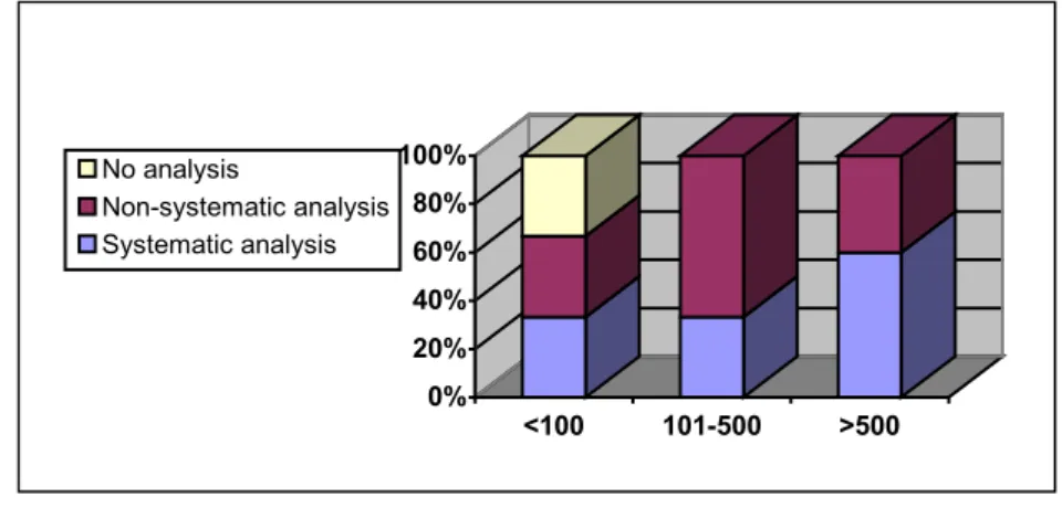
Small airlines (less than 100 employees) have difficulty in setting up an analysis programme, whereas larger airlines (more than 100 employees) all perform some kind of analysis. Systematic analysis is performed mainly by airlines having more than 500 employees.
Figure 2 illustrates what kind of analysis is performed based on the size of the airline (number of employees):
Figure 2 2.4.4 Data frame layout documents
Eleven operators had a comprehensive set of data frame layout documents for their entire fleet. Ten of them performed flight parameter analyses, including six who did it systematically.
Four operators had incomplete or partially outdated documents. Five did not store any documents (they were stored by a sub-contractor instead) or did not even know if the documents existed.
Note: one sub-contractor, who typed in data frame layout documents into a computer system, confirmed these problems, stating that: “hardcopy of these documents are not always readable, (…) and often incomplete. Customers provide the data frame layout document but often forget the
conversion functions that go with parameters and the calibration reports”.
Figure 3
Airlines having data frame layout documents
55% 25% 20%
Have all documents Have incomplete documents Have none 0% 20% 40% 60% 80% 100% <100 101-500 >500 No analysis Non-systematic analysis Systematic analysis
Only seven out of 20 airlines (or 35%) using FDRs filed their data frame layout documents with the regional services of the Civil Aviation Authority. It is interesting to note that these documents were not necessarily complete, or up to date.
Just as for the analysis of recorded parameters, it was mainly small and medium airlines that had incomplete data frame layout documents.
This problem was especially true for aircraft that had been operated by a variety of operators over the years and on which systems had been modified without actually updating data frame layout documents accordingly.
Note: The problem of having obsolete data frame layout documents is also evident in cases outside of France. The NTSB produced a similar study in 1997.
2.4.5 Measuring and processing channel calibration
None of the surveyed airlines calibrated their aircraft’s measuring and processing channels.
Fifty-five percent of the surveyed airlines checked each of the elements of the measuring and processing channel independently during maintenance operations. For other airlines, checks were only partial or were not performed at all.
Figure 4
2.4.6 Summary
Of the 20 French airlines surveyed:
• 55 percent had a comprehensive set of data frame layout documents for their fleet;
• 35 percent had filed their data frame layout documents with the local Civil Aviation Authority;
Airlines checking the elements of the measuring and processing channels
55% 35% 10% All elements Some elements None
• None calibrated the measuring and processing channels;
• 55 percent checked the various elements of the measuring and processing channels of mandatory parameters;
• 85 percent performed an analysis of the parameters, including 45 percent systematically and 40 percent not systematically.
Of the 11 airlines that had data frame layout documents, 90 percent performed parameter analyses.
3 - CONCLUSIONS
Investigative bodies often encounter problems with the quality of recorded data and data frame layout documents.
These FDR read-out and analysis issues are detrimental to air safety by slowing down or restricting technical investigations aimed at preventing future accidents. Poor data quality is due to several factors, including:
• inadequate FDR maintenance;
• data frame layout documents not being archived or updated, especially following a reprogrammed FDAU or a change of operator;
• incomplete check of recorded parameters;
• partial checking of the measuring and processing channels elements, which does not guarantee a satisfactory operation of the channel as a whole.
These issues are often linked to poor specific knowledge about FDRs, especially for airlines with less than 100 employees. This may be due to the complexity of the regulations.
4 - SAFETY RECOMMENDATIONS
Note: In accordance with Directive 94/56, Article 10 of the European Union concerning accident investigations, a safety recommendation does not, under any circumstances, constitute a presumption of blame or responsibility related to an accident or incident.
4.1 Installation of FDRs on Aircraft
On 24 March 2001, a DHC 6 registered F-OGES crashed in Saint Barthélémy (French West Indies) but was not equipped with an FDR (10), which significantly
delayed the determination of the causes of the accident. In the light of these difficulties, the BEA recommended that:
• the DGAC and the JAA urgently take into account, for safety reasons,
the need for flight recorders for the rapid determination of the causes and circumstances of accidents which occur in public air transport and that, to this end, these organizations:
- impose as soon as possible, without any possible exemptions,
the carriage of at least one flight recorder on aircraft operating for public transport with a maximum certificated takeoff weight less than 5,700 kg and whose maximum approved passenger seating configuration is ten seats or more, whatever the date of certification may be;
- extend these provisions to airplanes of the same type
transporting cargo;
- study the extension of these provisions to helicopters operated
for public transport.
The SFACT responded in 2004 by stating that the JAA’s Equipment Subcommittee (EGSC) and Flight Recorder Subgroup (FRSG) had proposed a new wording of the relevant JAR OPS 1 paragraph: “to extend the mandatory installation aircraft of a CVR to aircraft weighing less than 5.7 tons and more than 9 passengers, regardless of the date of issue of the individual Certificate of Airworthiness and of the engine type”.
(10) This aircraft was not required by French regulations to be equipped with an FDR since the
4.2 Data Frame Layout Documents
The availability of data frame layout documents, which have to be obtained prior to any read-out, is one of the main problems facing FDR analysis. ICAO Annex 6, Part I, Attachment D stipulates that operators have to keep such documents up to date. The French regulation of 12 May 1997 requires that operators retain data frame layout documents. However, these documents are often missing or incomplete, and seldom filed with the regional services of the French Civil Aviation authorities. Consequently, the BEA recommends that:
• the DGAC ensure that all operators and regional services of the
French Civil Aviation authorities possess identical, up to date and comprehensive data frame layout documents.
And that:
• the ICAO ensure, through its audit procedures, that Contracting States
ensure that their operators can rapidly provide comprehensive and up-to-date data frame layout documents.
In addition, the use of electronic memory cards in FDRs can generate the need for new technical specifications
Consequently, the BEA recommends that:
• the EASA define the regulatory requirements to have data frame
layout information recorded on FDRs themselves, in a format that is readable by investigative bodies.
4.3 Recording Quality
ICAO Annex 6, Part I, eighth Edition and ED112 both stipulate that corrective actions must be taken as soon as a mandatory parameter is incorrectly recorded. European and French regulations have no such requirements.
Annex 6 and ED112 mention the problem of “significant period of poor quality data”, but European texts do not. This type of problem may indeed seriously hinder any kind of analysis.
Finally, some recordings do not match with the chronology of the flights. This can be seen through time period overlaps, anachronisms and significant loss of data. Consequently, the BEA recommends that:
• the DGAC ensure, in cooperation with the JAA, that European
regulations be updated to meet the standards of ICAO Annex 6 in terms of necessary corrective actions when a mandatory parameter is not correctly recorded or the chronological recording structure does not match the history of the flights performed.
4.4 Verification of Recorded Parameters
Numerous mid-size operators lack adequate resources to periodically verify the recorded parameters on FDRs themselves. This task is therefore sub-contracted, but the reports provided by sub-contractors are often informal and are difficult to interpret for non-specialists.
Defining a guideline for parameters’ check reports is desirable so as to make them more readable and understandable by operators’ flight safety departments and, if necessary, by investigative bodies.
Consequently, the BEA recommends that:
• the DGAC study, in cooperation with the BEA, a formalized report
template for the verification of mandatory parameter recordings
Note: detailed verification reports could contain the following items:
1. A comprehensive list of each parameter to be checked, and for each of them:
-the allocation in the data frame (frame, sub-frame, word, least significant bit, most significant bit) -the equations used to convert recorded values into corresponding physical values expressed in engineering units.
2. Graphs of the checked parameters to show their evolution during cruise, take-off and landing phases of a same flight. Each graph should:
-display a time period of 3 to 5 minutes,
-have a time axis that is readable and graduated every 10 or 20 seconds,
-clearly list the date, time, phase of flight (take-off, climb, stabilized cruise, descent, approach or landing), departure and arrival airports,
-legibly list on the vertical axis the values of parameters in engineering units, -have each graphed parameter legibly labeled,
-have a table showing the values in engineering units using the same time interval as the corresponding graph.
3. An analysis of the validity of parameters based on graphs and corresponding tables.
-This analysis should indicate parameter validity by showing samples of recorded values in engineering units.
-This analysis could be based on some characteristic points in a flight (11), on manufacturer-specified performances, or on the history of procedures actually performed during the analyzed flight.
4. A check on the chronological structure of the complete recording, based on the aircraft flight history
-This check could be based on the evolution of some basic parameters, such as airspeed or pressure altitude, for a particular phase of flight.
-A check based on graphs for the entire length of the recording would be sufficient.
4.5 Calibration of measuring and processing channels
This study has illustrated the need to systematically calibrate measuring and processing channels when any of the following occur:
• a new operator puts an aircraft in service,
• after a modification of the FDR system,
• after each major overhaul.
However, the calibration of measuring and processing channels is not required by European regulations.
Consequently, the BEA recommends that:
• the DGAC, in cooperation with the JAA, study a comprehensive
calibration programme for mandatory parameters’ measuring and processing channels.
List of Appendices
Appendix I
EUROCAE Document 55, May 1990
Appendix II
Extracts from EUROCAE Document 112, March 2003
Appendix III
Extracts from regulatory texts
Appendix IV
EUROCAE Document 55, May 1990
ED55 (12), published in May 1990, defines the “Minimum Operational Performance
Specifications for Flight Data Recorder Systems”. Current European regulations references to this document may be replaced by references to ED112, which is meant to supersede ED55.
The following annexes to ED55 relate to certification and monitoring of recorders:
• Annex 3: Flight testing
• Annex 4: Maintenance practices
FDR system installation check
Annex 3 (A3) defines a combination of ground and flight tests to demonstrate correct operation of the installed system and include the following:
• tests on prototype installation for the certification of newly-installed FDR systems
• tests for series installations.
During these tests, the installer must demonstrate correct correlation between instrument values and recorded values.
Paragraph A3.3 requires that the following documentation be produced as a result of the tests:
• a report
• flight test recording in “graphical and tabular format”
ED55, Chapter 2, paragraph 2.17 lists the recommended documents for the certification of newly-installed FDR systems, including: “Conversion and logic for translation of the recorded data stream into parameters expressed in engineering units”.
FDR system maintenance
Annex 4 (A4) defines all the maintenance tasks recommended by the EUROCAE. It stipulates that the maintenance programme should be defined by the installer: “The system installer will need to perform an analysis of the system to identify those parts of system (…) which would not be readily apparent to (…) the maintenance personnel. Appropriate inspections and functional checks, together with the intervals at which these would need to be performed, will need to be established as indicated by the analysis (13).”
(12) EUROCAE Documents (ED’s) are currently used as a reference by regulatory authorities. (13) ED55, Annex 4, paragraph A4.1.1
This maintenance programme must include the following maintenance tasks related to recording quality:
A/ Parameter recording check
Paragraph A4.1.3 states that “a copy recording of a record made in flight should be made” in order to “reveal defective or noisy sensors”.
The installer determines the intervals between checks, though table A4-2 suggests 2,000 hours or 12 months. This table contains the following additional recommendations:
• “copy and replay at least the last 15 minutes of flight recording”;
• “check all mandatory parameters are active and are of acceptable quality”. B/ Test procedure for measuring and processing channels calibration
Calibration checks demonstrate if conversion equations provided by operators are appropriate. These equations should convert recorded binary words into parameters expressed in engineering units. If conversions are shown to be inappropriate, acquisition channel elements or conversion equations should be adjusted.
The fact that this task should be performed on the entire FDR system and therefore should be done onboard aircraft should here be underlined. It should not be mistaken for bench tests performed for FDR or acquisition units.
Paragraph A4.2 describes the test procedure in detail.
• tests must be performed for “a newly installed flight recorder system and at intervals thereafter”. They apply to the acquisition of all parameters and discretes (paragraph A4.2.2);
• the operator should fill out a “tabulated (…) calibration record sheet” that shows the correlation between simulated inputs (at the sensor level), acceptable output value ranges (at the FDR level) and the values indicated on the test set. Table A4-1 gives an example of such a sheet;
• sensor outputs may be simulated by suitable test equipment (paragraph A4.2.5). Measuring devices may be used when a sensor output does not provide any indication in the cockpit (paragraph A4.2.7).
C/ Calibration documents
Paragraph A4.1.4 recommends that the operator document sensor calibration data that should be “made available when required to the accident investigation authorities”.