BloomFlash: Bloom Filter on Flash-based Storage
Biplob Debnath
†,1,
Sudipta Sengupta
‡,
Jin Li
‡,
David J. Lilja
∗,
David H.C. Du
∗ †EMC Corporation, Santa Clara, CA, USA
‡
Microsoft Research, Redmond, WA, USA
∗University of Minnesota, Minneapolis, MN, USA
Email: [email protected],
{sudipta, jinl}@microsoft.com, [email protected], [email protected]
Abstract—
The bloom filter is a probabilistic data structure that provides a compact representation of a set of elements. To keep false positive probabilities low, the size of the bloom filter must be dimensioned a priorito be linear in the maximum number of keys inserted, with the linearity constant ranging typically from one to few bytes. A bloom filter is most commonly used as an in-memorydata structure, hence its size is limited by the availability of RAM space on the machine. As datasets have grown over time to Internet scale, so have the RAM space requirements of bloom filters. If sufficient RAM space is not available, we advocate that flash memory may serve as a suitable medium for storing bloom filters, since it is about one-tenth the cost of RAM per GB while still providing access times orders of magnitude faster than hard disk.
We present BLOOMFLASH, a bloom filter designed for flash memory based storage, that provides a new dimension of tradeoff with bloom filter access times to reduce RAM space usage (and hence system cost). The simple design of a single flat bloom filter on flash suffers from many performance bottlenecks, including in-place bit updates that are inefficient on flash and multiple reads and random writes spread out across many flash pages for a single lookup or insert operation. To mitigate these performance bottlenecks,BLOOMFLASHleverages two key design innovations: (i) buffering bit updates in RAM and applying them in bulk to flash that helps to reduce random writes to flash, and (ii) a
hierarchicalbloom filter design consisting of component bloom filters, stored one per flash page, that helps to localize reads and writes on flash. We use two real-world data traces taken from representative bloom filter applications to drive and evaluate our design. BLOOMFLASHachieves bloom filter access times in the range of few tens of𝜇sec, thus allowing up to order of tens of thousands operations per sec.
I. INTRODUCTION
The bloom filter is a bit-vector data structure that provides a compact representation of a set of elements (keys). It supports insertion of elements and membership queries. A membership answer is probabilistically correct in the sense that it allows a small probability of a false positive (i.e., an incorrect answer for a non-member element). The bloom filter allows tradeoffs between small size (compactness) and low false positives (accuracy). To keep false positives low, the size of the bloom filter must be dimensioneda priorito be linear in the maximum number of keys inserted, with the linearity constant typically ranging from one to few bytes. A bloom filter is most commonly used as anin-memorydata structure,
1Work done when the author was a PhD student at the University of Minnesota
hence its size is limited by the availability of RAM space on the machine.
An element lookup in a bloom filter involves hashing it to some number, say 𝑘, of different positions in the vector and check that these bits are all1– if so, it is concluded that element is in the set that the bloom filter represents, otherwise not. An element insertion involves setting the corresponding𝑘
bit positions to1. It can now be easily seen how a false positive can happen during a lookup – an element may not have been inserted in the bloom filter but may have had all its 𝑘 bit positions set to1during insertions of other elements. Further notation on bloom filters and discussion of false positive probabilities is provided in Section III-B.
An excellent survey of bloom filter applications is provided in [1]. A common use of bloom filters is to identify non-existent elements so as to avoid high query latencies involved with accesses down the storage hierarchy or across the net-work. Many data center applications, for example, Venti [2], a data deduplication system, and Google Big Table [3], use bloom filters to detect unique data, which helps to avoid slow secondary storage accesses. However, the size of the bloom filter in some applications is too big to fit in main memory. As datasets have grown over time to Internet scale, so have the RAM space requirements of bloom filters, even after partitioned processing of data across multiple servers. In current data center applications, it is not uncommon to allocate upwards of few GB of RAM for storing bloom filters.
When sufficient RAM space is not available, it may be necessary to store the bloom filter in magnetic disk-based storage. However, as bloom filter operations are randomly spread over its length, the slow random access (seek) per-formance of disks, of the order of 10 msec, becomes a huge bottleneck. The use of independent hash functions destroys any locality that may be present in the element space, hence, even using a RAM based cache does not help to improve bloom filter performance. Since flash memory has faster read performance, of the order of 10-100𝜇sec in currently available Solid State Drives (SSDs), it is a viable storage option for implementing bloom filters and striking tradeoffs between high cost of RAM and fast bloom filter access times. Flash memory, however, provides relatively slow performance for random write operations (vs. reads and sequential writes), as explained in Section III. The aim of this paper is to design a flash-based bloom filter which is aware of flash memory characteristics.
There are two types of popular flash devices, NOR and NAND flash. NAND flash architecture allows a denser layout
2011 31st International Conference on Distributed Computing Systems
Fig. 1. Flash-based Solid State Disk (SSD)
and greater storage capacity per chip. As a result, NAND flash memory has been significantly cheaper than DRAM, with cost decreasing at faster speeds. NAND flash characteristics have lead to an explosion in its usage in consumer electronic devices, such as MP3 players, phones, caches and Solid State Disks (SSDs). In the rest of the paper, we use NAND flash based SSDs as the architectural choice and simply refer to it as flash memory. We describe SSDs in detail in Section II.
In this paper, we present the design and evaluation of BLOOMFLASH, a flash memory based bloom filter, that pro-vides a new dimension of tradeoff with bloom filter access times to reduce RAM space usage (and hence system cost). The simple design of a single flat bloom filter on flash suffers from many performance bottlenecks, including in-place bit updates that are inefficient on flash and multiple reads and random writes spread out across many flash pages for a single lookup or insert operation. To mitigate these performance bottlenecks, we exploit two key design decisions: (i) buffering bit updates in RAM and applying them in bulk to flash using two different flushing policies that helps to reduce random writes to flash, and (ii) a hierarchical bloom filter design consisting of component bloom filters, stored one per flash page, that helps to localize reads and writes on flash. We use two real-world data traces taken from representative bloom filter applications to drive and evaluate our design. Our experimental results show that BLOOMFLASH achieves bloom filter access times in the range of few tens of𝜇sec, thus allowing up to about 28,500 ops/sec.
The rest of the paper is organized as follows. We provide an overview of flash memory in Section II. In Section III, we develop the design of BLOOMFLASH. In Section IV, we describe two real-world data center applications and used them to evaluate and justify the design choices in BLOOMFLASH. We review related work in Section V. Finally, we conclude in Section VI.
II. FLASH-BASEDSTORAGEOVERVIEW
Figure 1 gives a block-diagram of an NAND flash based SSD. In flash memory, data are stored in an array of flash blocks. Each block spans 32-64 pages, where a page is the smallest unit of read and write operations. A distinguishing feature of flash memory is that read operations are very fast compared to magnetic disk drive. Moreover, unlike disks, ran-dom read operations are as fast as sequential read operations
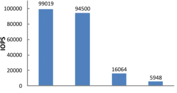
99019 94500 16064 5948 0 20000 40000 60000 80000 100000
seq-reads rand-reads seq-writes rand-writes
IO
P
S
Fig. 2. IOPS for sequential/random reads and writes using 4KB I/O request size on a 160GB fusionIO drive.
as there is no mechanical head movement. A major drawback of the flash memory is that it does not allow in-place updates (i.e., overwrite). Page write operations in a flash memory must be preceded by an erase operation and within a block, pages need be to written sequentially. Thein-place updateproblem becomes complicated as write operations are performed in the page granularity, while erase operations are performed in the block granularity. The typical access latencies for read, write, and erase operations are 25 microseconds, 200 microseconds, and 1500 microseconds, respectively [4].
The Flash Translation layer (FTL) is an intermediate soft-ware layer inside SSD, which makes linear flash memory device act like a virtual disk. The FTL receives logical read and write commands from the applications and converts them to the internal flash memory commands. To emulate disk like in-place update operation for a logical page (𝐿𝑝), the FTL
writes data into a new physical page (𝑃𝑝), maintains a mapping
between logical pages and physical pages, and marks the previous physical location of𝐿𝑝as invalid for future garbage
collection. Although FTL allows current disk based application to use SSD without any modifications, it needs to internally deal with flash physical constraint of erasing a block before overwriting a page in that block. Besides thein-place update
problem, flash memory exhibits another limitation – a flash block can only be erased for limited number of times (e.g., 10K-100K) [4]. FTL uses various wear leveling techniques to even out the erase counts of different blocks in the flash memory to increase its overall longevity [5]. Recent studies show that current FTL schemes are very effective for the workloads with sequential access write patterns. However, for the workloads with random access patterns, these schemes show very poor performance [6], [7], [8], [9], [10], [11], [12]. One of the design goals of BLOOMFLASH is to use flash memory in FTL friendly manner.
III. BLOOMFILTER ONFLASH A. Coping with Flash Constraints
Our design is driven by the need to work around small random write operations that are not efficient on flash media. Small random writes effectively need to update data portions within pages. Since a (physical) flash page cannot be updated in place, a new (physical) page will need to be allocated and
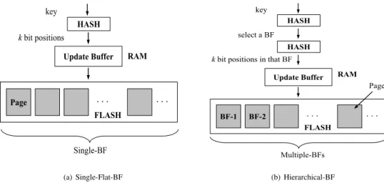
(a) Single-Flat-BF (b) Hierarchical-BF
Fig. 3. Bloom filter designs on flash: Single flat bloom filter vs. hierarchical bloom filter.
the unmodified portion of the data on the page needs to be relocated to the new page.
To validate the performance gap between sequential and random writes on flash, we used Iometer [13], a widely used performance evaluation tool in the storage community, on a 160GB fusionIO SSD [14] attached over PCIe bus to an Intel Core 2 Duo E6850 3GHz CPU. The number of worker threads was fixed at 8 and the number of outstanding I/Os for the drive at 64. The results for IOPS (I/O operations per sec) on 4KB I/O request sizes are summarized in Figure 2. Each test was run for 1 hour. The IOPS performance of sequential writes is about 3x that of random writes and worsens when the tests are run for longer durations (due to accumulating device garbage collection overheads). We also observe that the IOPS performance of (random/sequential) reads is about 6x that sequential writes. (The slight gap between IOPS performance of sequential and random reads is possibly due to prefetching inside the device.)
Given the above, in order to use flash in the most efficient way we have focused on reducing random write operations as much as possible. However, this is very challenging as bloom filter operations are inherently random in nature.
B. BloomFlash Design
BLOOMFLASHstores the bloom filter bits on flash and uses RAM to buffer bit updates resulting from element insertions so as to mitigate flash writing and garbage collection overheads that could result from excessive in-place bit updates to flash. The bloom filter organization on flash is divided into pages corresponding to flash page sizes that are typically 2KB or 4KB. All read and write operations on flash are performed at the page level. We begin with a single flat bloom filter design and then refine it with the objective of localizing read and write operations, corresponding to element lookups and insertions, to within a single flash page. We present and investigate two different policies for flushing buffered page updates to RAM that work with either design.
We begin with some notation. Let𝑚 be the total number of bits in the bloom filter. Let𝑛be the maximum number of
elements (keys) inserted. The insertion of a key into the bloom filter involves selecting𝑘bit positions, using𝑘different hash functions, and setting these𝑘bits to1. A lookup for a key in the bloom filter needs to compute the𝑘bit positions using the
𝑘hash functions and checking whether all these bit positions are 1 – if so, the key is inferred to be in the bloom filter. Clearly, there is a chance of afalse positiveevent here, since these𝑘 positions might have their bits to1by other inserted keys, while the current key may not have been inserted at all. After insertion of 𝑛 keys, the probability,𝐹 𝑃(𝑛, 𝑚, 𝑘) of a false positive during lookup can be shown to be
𝐹 𝑃(𝑛, 𝑚, 𝑘) = ( 1− ( 1− 1 𝑚 )𝑘𝑛)𝑘 ≈(1−𝑒−𝑘𝑛/𝑚)𝑘
Given the maximum number of elements inserted 𝑛 and any one of two quantities𝑚and𝑘, we can minimize the false positive probability by choosing the other quantity as per the equation
𝑘=𝑚
𝑛 ln 2 (1)
C. Single Flat Bloom Filter on Flash
In our first design, the bloom filter is laid out in sequential logical address space on flash as shown in Figure 3(a). With a flash physical page size of𝑃 bytes (typically equal to 2KB or 4KB), each page of flash holds8𝑃 bits, so that the number of flash pages required is 𝑝 = ⌈8𝑚𝑃⌉. Henceforth, we will assume that𝑚is an integral multiple of8𝑃. During an element lookup, the𝑘different bit positions are translated to (logical) flash page ids and offsets. Each flash page is read to check whether the corresponding bit(s) within it is0or1. A lookup can terminate with a negative answer when a bit position is read as0 (in which case the remaining bit positions, if any, need not be read). An element insertion operation needs to set (at most)𝑘bit positions to1(if they are not already set to1). Because flash page writes are inefficient, these bit update operations are deferred using a buffer in RAM. The idea is collect multiple updates for the same page and apply them
at once. Since RAM buffer space is limited, we need to periodically flush some of the buffered updates to flash so as to accommodate new updates. It appears that this flushing policy is critical for designing an efficient flash-based bloom filter. We discuss different buffer flushing policies separately after we describe two designs for bloom filter layout on flash. Due to the random nature of the𝑘bit positions selected for each element, an element lookup will almost always involve
𝑘 different flash page reads. This makes the element lookup time about 𝑘 times that of a single flash page read. Also, an element write involves updates to about 𝑘 flash pages (could be less if some of the 𝑘 bits are already set) – thus each element write leads to bit updates on about 𝑘 different flash pages to be buffered in RAM. Both of these are shortcomings of this first simple design, which we address in the next design that is the choice for BLOOMFLASH.
D. Using Hierarchical Bloom Filter Design to Localize Reads and Writes
The first design suffers from the drawback that a bloom filter lookup (almost always) involves𝑘flash page reads, since the random nature of the 𝑘 bit positions will place them in different flash pages with high probability. Although flash media is good for random reads (vs. hard disk), we aim to improve performance further by targeting just a single flash page read for a lookup operation on the bloom filter.
Our solution approach is to partition the single flat bloom filter into many smaller componentbloom filters, each of the size of one flash page (e.g., 4KB) as shown in Figure 3(b). We call the resulting data structure ahierarchicalbloom filter. With a flash page size of 𝑃 bytes, this gives 𝑝 = ⌈8𝑚𝑃⌉
component bloom filters, each fitting on one flash page. To insert or lookup an element, a first hash function is used to identify the bloom filter it should belong into. Then, 𝑘 bit positions are identified within this bloom filter for setting or checking the bits. Thus, this design requires only one flash page read per element lookup. Moreover, this design also localizes bit position writes associated with an element insertion to within a single flash page – in contrast, in the first design, an element insertion involves setting bits in (almost always) 𝑘 flash pages. Hence, insertion of 𝑛′ elements can make at most𝑛′flash pages dirty in the worst case, while that number is 𝑘𝑛′ in the first design. This aspect of the second design helps to reduce flash page writes.
We next analyze the false positive probability of this com-posite bloom filter data structure.
Analysis of False Positive Probability
In BLOOMFLASH, the overall bloom filter data structure is realized by multiple component bloom filters and each element is assigned to one component bloom filter (using a hash function). We analyze the false positive probability of this composite bloom filter data structure. Suppose that 𝑛 keys are inserted into the hierarchical bloom filter and this leads to 𝑛𝑖 element insertions in the𝑖-th component bloom filter
for𝑖= 1,2, . . . , 𝑝. Let the size of each small bloom filter be
𝑚′= 8𝑃 bits. As before,𝑘is the number of bit positions that is checked in each small bloom filter for an element lookup. The probability of an element hashing to the𝑖-th component bloom filter is1/𝑝 and the false positive probability of that element in that component bloom filter is 𝐹 𝑃(𝑛𝑖, 𝑚′, 𝑘).
Thus, the false positive probability of the hierarchical bloom filter is given by 1 𝑝 𝑝 ∑ 𝑖=1 𝐹 𝑃(𝑛𝑖, 𝑚′, 𝑘)
Using Jensen’s equality for convex functions, it can be shown that the false positive probability of the hierarchical bloom filter is at least that of that of the (equivalent) single flat bloom filter𝐹 𝑃(𝑛, 𝑚, 𝑘)(in the first design), that is
1 𝑝 𝑝 ∑ 𝑖=1 𝐹 𝑃(𝑛𝑖, 𝑚′, 𝑘)≥𝐹 𝑃(𝑛, 𝑚, 𝑘)
with equality if and only if all the 𝑛𝑖’s are equal, i.e., the
hashing of elements to component bloom filters achieves exactly equal distribution of elements across the component bloom filters. In fact, as the distribution of elements across component bloom filters gets more skewed (or, unbalanced), the gap widens between the false positive probabilities of the hierarchical bloom filter and single flat bloom filter designs. A simple way to understand this effect is as follows: as the number of elements inserted into a component bloom filter increases beyond the average of 𝑛/𝑝, its false positive rate increases non-linearly above 𝐹 𝑃(𝑛, 𝑚, 𝑘); hence, the false positive probabilities of above-average occupancy component bloom filters isnotaveraged out by that of other below-average occupancy small bloom filters.
Thus, it might be necessary to enforce fairly equal load balancing of elements across component bloom filters in this design in order to keep the false positive probability comparable to that of the single flat bloom filter design. One simple way to achieve this is to use thepower of two choice ideafrom [15] that has been used to balance a distribution of balls thrown into bins. With a load balanced design for hierarchical bloom filter, each element would be hashed to two candidate component bloom filters and actually inserted into the one that has currently fewer inserted elements. During lookup, each element is looked up in both of its candidate component bloom filters (hence bloom filter lookup times would double).
With the help of our experimental setup (as described in Section IV), we have found that the single-hash based assignment of an element to a component bloom filter achieves fairly equal load balancing of elements across component bloom filters. Hence, a more intricate design for load balancing is not required. We observe in our evaluations (on the data traces used) that the ratio of elements inserted in the maximum occupancy bloom filter to that in the minimum occupancy bloom filter is about 1.1, hence the distribution of each bin is within 10% from the average. Because of this, the false positive probability of the composite bloom filter is about the same as that of the (equivalent) single flat bloom filter. An intuitive explanation for why this fairly equal load balancing
is achieved is that the number of elements inserted is orders of magnitude more than the number of component bloom filters – for example, with a flash page size of 𝑃 = 4096
bytes and𝑚/𝑛= 8, the number of component bloom filters is𝑛/4096. Hence, by deriving analogy from the well studied balls-and-bins problem, we expect the random assignment of balls to bins to achieve a fairly well balanced distribution. (As a side note, using the idea of two choices for inserting an element into a component bloom filter brings down the ratio of elements inserted in the maximum occupancy bloom filter to that in the minimum occupancy bloom filter to about 1.001.)
E. Buffering Updates in RAM to Reduce Flash Writes
We can buffer updates in RAM for each of the bloom filter designs above so as to reduce the number of flash writes. Since in-place updates to (logical) flash pages actually lead to new (physical) pages being allocated and written and increases garbage collection activity, this strategy can help to reduce write amplification and garbage collection overheads. Additionally, the latency of bloom filter reads could also decrease somewhat since a bit position (write) that is buffered in RAM can be read with reading the containing page on flash. Insertion Group the buffered updates by the page id.
To realize this strategy, we group and store in RAM bit position updates (changes from0to1as a result of element insertion) for the same flash page – each update records a bit position offset within the page and all updates within a page share a common page id information. These updates are flushed to flash when the turn arrives to flush the correspond-ing page. When multiple contiguous flash pages in logical address page are flushed together (vs. each page separately when their turn arrives), the write performance improves due to the large (sequential) nature of the writes. Hence, we apply the scheduling of pages flushed to flash in the granularity of
contiguous (logical) page groupsrather than individual pages. We evaluate the performance of different page group sizes in Section IV and fix a page group size of 16 in our system implementation.
We investigate two page group flushing policies as follows: ∙ Dirtiest group first: Under this policy, the page group that contains the largest number of bit position updates (i.e., contains the maximum dirty bits) is given priority for flushing to flash. This greedy policy minimizes the total number of write operations. Since write operations more expensive than read operations on flash media, this is the conventional buffering policy. However, this policy ignores the performance degradation that can result from writing page groups in arbitrary order (vs. their ordering in the logical address space) since this results in random write operations to flash.
∙ Groups in sequential order: Under this policy, page groups are flushed out in sequential order in logical address space (with wraparound when the last page group is reached). This treats the bloom filter storage area on flash like an append log (with wraparound) and aims to reap the write performance benefits of using flash in a
log-structured manner (the latter has been reported in earlier work [10], [11], [12], [16], [17], [18]).
Flushing of a page group is triggered when a bit position update, resulting from an element insertion process, needs to be buffered in RAM and a pre-configured space threshold in RAM for storing buffered updates is exceeded. Only one page group is flushed at a time and is chosen in accordance with either of the above flushing policies. We investigate the impact of varying buffer space thresholds on bloom filter performance.
IV. EVALUATION
In this section, we evaluate the design of BLOOMFLASHin Fusion-IO [14] and Samsung [19] Solid State Drives (SSDs) with the help of two real-world applications.
A. Applications Used
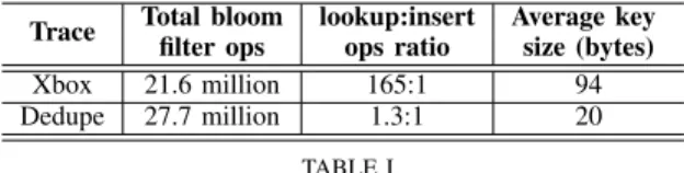
We describe two real-world data center applications that use bloom filters to reduce data lookup latencies in the system. Data traces obtained from real-world instances of these applications is used to drive and evaluate the design of BLOOMFLASH. The properties of the two traces in terms of associated bloom filter operations are summarized in Table I. Online Multi-player Gaming
Online multi-player gaming technology allows people from geographically diverse regions around the globe to participate in the same game. The number of concurrent players in such a game could range from tens to hundreds of thousands and the number of concurrent game instances offered by a single on-line service could range from tens to hundreds. An important challenge in online multi-player gaming is the requirement to scale the number of users per game and the number of simultaneous game instances. At the core of this is the need to maintain server-side state so as to track player actions on each client machine and update global game states to make them visible to other players as quickly as possible. These functionalities map tosetandgetkey operations performed by clients on server-side state. The real-time responsiveness of the game is, thus, critically dependent on the response time and throughput of these operations.
In such online multi-player gaming applications, front-end caching servers are used to scale a back-end of partitioned database servers implementing a key-value store. Specifically, we consider the Microsoft Xbox LIVE Primetime online mul-tiplayer game [20]. This application frequently uses lookups on non-existing keys to implement the game logic. Key writes arriving at a end server are broadcast to all other front-ends so that they can insert that key into their local bloom filters. For a key read operation, if the key is not in the local bloom filter of the front-end, that frontend can return null to the client; otherwise, the read is sent to the appropriate back-end database server.
We evaluate the performance of BLOOMFLASHon a large trace of get-set key operations obtained from real-world instances of Xbox LIVE Primetime [20] in which the key is a dot-separated sequence of strings with total length averaging
Trace Total bloomfilter ops lookup:insertops ratio Average keysize (bytes)
Xbox 21.6 million 165:1 94 Dedupe 27.7 million 1.3:1 20
TABLE I
BLOOM FILTER OPERATION STATISTICS IN THE TWO TRACES USED IN THE PERFORMANCE EVALUATION. THEXBOX TRACE IS A LOOKUP INTENSIVE TRACE WHILE THEDEDUPE TRACE IS AN
INSERT(I.E.,UPDATE)INTENSIVE TRACE.
94 bytes. The ratio of bloom filter lookup to insert operations in the trace is about 165:1.
Storage Deduplication
Deduplication is a recent trend in storage backup systems that eliminates redundancy of data across full and incremental backup data sets [21]. It works by splitting files into multiple chunks using a content-aware chunking algorithm like Rabin fingerprinting and using SHA-1 hash signatures for each chunk to determine whether two chunks contain identical data [21]. In inline storage deduplication systems, the chunks (or their hashes) arrive one-at-a-time at the deduplication server from client systems. The server needs to lookup each chunk hash in an index it maintains for all chunk hashes seen so far for that backup location instance – if there is a match, the incoming chunk contains redundant data and can be deduplicated; if not, the (new) chunk hash needs to be inserted into the index.
Because storage systems currently need to scale to tens of terabytes to petabytes of data volume, the chunk hash index is too big to fit in RAM, hence it is stored on hard disk. Index operations are thus throughput limited by expensive disk seek operations. Since backups need to be completed over windows of half-a-day or so (e.g., nights and weekends), it is desirable to obtain high throughput in inline storage deduplication systems. Typical in such systems (e.g., [22], [21]) is the use of a bloom filter to determine if a chunk hash has been seen earlier so that disk access latencies can be avoided for chunks that are seen for the first time (which is the majority of chunks in the first full backup of a dataset).
To obtain a chunk hash trace from real-world datasets, we have built a storage deduplication analysis tool that can crawl a root directory, generate the sequence of chunk hashes for a given average chunk hash size, and compute the number of deduplicated chunks and storage bytes. We use traces generated from this tool on an enterprise backup dataset to evaluate bloom filter performance. In this application, the key is a 20-byte SHA-1 hash of the corresponding chunk. The trace contains 27,748,824 total chunks and 12,082,492 unique chunks. Using this, we obtain the ratio of bloom filter lookup to insert operations in the trace as 1.3:1.
B. C Implementation
We have prototyped BLOOMFLASHin approximately 3000 lines of C code. To implement the𝑘hash functions for bloom filter access, we use MurmurHash [23]. We store the bloom filter data in the file system and turn off operating system buffering of file blocks so as to avoid any favorable effects due
3520 2275 4890 3044 5005 3056 0 1500 3000 4500 6000 XBox Dedupe ops per sec
No-Buffer Dirtiest-Group Sequential-Group-Order
Fig. 4. Single Flat BF Design on Fusion-IO (𝐶𝑎𝑐ℎ𝑒𝑆𝑖𝑧𝑒𝐹 𝑎𝑐𝑡𝑜𝑟= 4
and𝐺𝑟𝑜𝑢𝑝𝑆𝑖𝑧𝑒= 16)
to it. The value of𝑘is chosen to be6. Since the number of keys in each trace is known (i.e., the value of𝑛), we use equation(1) to determine the size𝑚of the bloom filter (single or hierarchi-cal). In the rest of this section, the value𝐶𝑎𝑐ℎ𝑒𝑆𝑖𝑧𝑒𝐹 𝑎𝑐𝑡𝑜𝑟= 𝑥implies that 𝑆𝑖𝑛𝑔𝑙𝑒𝐹 𝑙𝑎𝑡𝐵𝑙𝑜𝑜𝑚𝐹 𝑖𝑙𝑡𝑒𝑟𝑆𝑖𝑧𝑒∗𝑥
𝐹 𝑙𝑎𝑠ℎ𝑃 𝑎𝑔𝑒𝑆𝑖𝑧𝑒 number of update
entries are buffered in the RAM cache. We set the value of
𝐹 𝑙𝑎𝑠ℎ𝑃 𝑎𝑔𝑒𝑆𝑖𝑧𝑒to 4KB.
C. Evaluation Platforms
We use two different Solid State Drives (SSDs) to evaluate the performance of BLOOMFLASH. The first one is a Fusion-IO flash SSD [14] of capacity 80GB. The second one is a Samsung flash SSD [19] of capacity 100GB. The CPU is an Intel Core 2 Duo E6850 with a clock speed of 3GHz per core. We log the average number of ops/sec at a period of every 10,000 get-set operations during each run and then take the overall average over a run to obtain throughput numbers. To calculate latency, we divide total execution time by the total number ofget-setoperations.
D. Result Analysis
In this section, we first evaluate the effect of buffering in the
single flat BF design. Next, we evaluate the improvement of thehierarchical BF design. During these set of experiments, we have used𝐶𝑎𝑐ℎ𝑒𝑆𝑖𝑧𝑒𝐹 𝑎𝑐𝑡𝑜𝑟= 4and𝐺𝑟𝑜𝑢𝑝𝑆𝑖𝑧𝑒= 16, since this combination provides better throughput. Finally, we evaluate the impact of group size and cache size on the
hierarchical BFdesign.
Single Flat BF Design
Buffering helps to improve the performance of this design by 34%-42%. Figure 4 shows the performance trends of
single flat BFdesign for Xbox and dedupe traces running in Fusion-IO drive.
Xbox Trace.Buffering helps to improve throughput by 39%-42%. Without any buffering, we achieve only 3,520 ops/sec. However, with buffering, we achieve higher throughput. For the dirtiest-groupflushing policy, we achieve 4,890 ops/sec, while for the sequential-group-ordering, we achieve 5,005 ops/sec. The average key lookup time is 282.07𝜇sec, 202.78
24653 12318 26736 15640 26663 15630 0 7500 15000 22500 30000 XBox Dedupe ops per sec
No-Buffer Dirtiest-Group Sequential-Group-Order
(a) Fusion-IO 12829 4042 12757 5276 12973 4826 0 3500 7000 10500 14000 XBox Dedupe ops per sec
No-Buffer Dirtiest-Buffer Sequential-Group-Order
(b) Samsung Fig. 5. Hierarchical BF Design (𝐶𝑎𝑐ℎ𝑒𝑆𝑖𝑧𝑒𝐹 𝑎𝑐𝑡𝑜𝑟= 4and𝐺𝑟𝑜𝑢𝑝𝑆𝑖𝑧𝑒= 16)
𝜇sec, and 198.29 𝜇sec for no-buffering, the dirtiest-group
flushing, and thesequential-group-orderingflushing policies, respectively. As explained in Section III-E, buffering helps to reduce expensive flash write operations by applying the changes due to update operations in bulk to the underlying flash device, which consequently helps to improve throughput. In particular, buffering helps to reduce the total number of flash write operations approximately by 77% for the dirtiest-group policy and 75% for the sequential-group-ordering
policy.
Dedupe Trace.Buffering improves throughput approximately by 34%. It helps to improve throughput by reducing the total number of expensive flash write operations. It reduces write operations approximately by 87% for both the flushing policies. The dirtiest-group flushing policy achieves 3,044 ops/sec and the sequential-group-ordering achieves 3,056 ops/sec, while without any buffering, we achieve only 2,275 ops/sec. The average key lookup time is 422.63𝜇sec, 326.55
𝜇sec, and 325.15 𝜇sec for no-buffering, the dirtiest-group
flushing, and thesequential-group-orderingflushing policies, respectively.
From Figure 4, it is clear that the throughput is higher for Xbox compared to dedupe case. The main reason behind this trend is that Xbox workload is read-intensive, while dedupe workload is write-intensive. Since current flash-based SSDs provide comparatively faster read performance, certainly we achieve higher throughput for read-intensive Xbox trace. On the other hand, the average key lookup time is higher for dedupe case due to frequent garbage collection operations inside SSDs incurred by excessive write operations.
Hierarchical BF Design
Hierarchical design improves the performance compared to the Single BF design since it localizes read and write operations to a single place for each lookup and insert operation. The improvement gain is linearly related with the value chosen for
𝑘(i.e., number of hash functions).
Figure 5 shows the performance trends of hierarchical design for Xbox and dedupe traces running in Fusion-IO and Samsung drives. The trends in Figure 5(a) show that
thehierarchical BF designimproves throughput 5.11x-7.00x and latency 5.60x-7.38x, compared to the Single Flat BF design for the Fusion-IO drive. The main reason for this improvement is the following. Thesingle flat BF designuses
𝑘= 6different hash functions for the bloom filter operations and these hash functions mostly perform random I/Os in the six different flash locations. In contrast, thehierarchical BF design uses one I/O per bloom filter operation, irrespective of the value of𝑘. In addition, this design inherently localizes the updates in the buffer, which consequently helps to further improve throughput by reducing random write operations. This is also evident from the result trend that on average,
hierarchical BF design provides approximately six times more throughput. Table II and III give summaries of the improvement in hierarchical BF design for the Fusion-IO drive. We also observe similar trends for the Samsung drive.
Xbox Trace.Compared to single flat BF design, throughput improves by 5.33x-7.00x and latency improves by 5.60x-7.38x for the Fusion-IO drive. In particular, Figure 5(a) shows that with hierarchical BF design for Xbox, dirtiest-groupflushing policy achieves 26,736 ops/sec and sequential-group-ordering achieves 26,663 ops/sec, while without any buffering, we achieve only 24,653 ops/sec. Thus, both dirtiest-groupandsequential-group-orderingflushing policies improve throughput by 8%, compared to having no buffer. Unlike, thesingle flat BF case, here buffering does not significantly help to improve throughput. Buffering helps to reduce total number of flash write operations by 3%. This occurs due to impact of hierarhical BF design as it localizes the update operations from six different flash locations to single flash location, consequently reducing the total number of flash I/O operations. Compared to single flat BF in Figure 4, dirtiest-group flushing, sequential-group-ordering flushing, and no buffering policies achieve 5.45x, 5.33x, and 7.00x higher throughput, respectively. The average key look up time is 35.35𝜇sec, 35.36𝜇sec, and 38.20𝜇sec, respectively.
Figure 5(b) shows that with Samsung drive, for Xbox, the
dirtiest-group flushing policy achieves 12,757 ops/sec and
sequential-group-ordering achieves 12,973 ops/sec, while without any buffering, we achieve only 12,829 ops/sec. Thus,
Single-Flat-BF Hierarchical-BF Improvement Xbox Dedupe Xbox Dedupe Xbox Dedupe (ops/sec) (ops/sec) (ops/sec) (ops/sec)
No-Buffer 3,520 2,275 24,653 12,318 7.00x 5.41x
Dirtiest-Group 4,890 3,044 26,736 15,640 5.47x 5.13x
Sequential-Group-Order 5,005 3,056 26,663 15,630 5.33x 5.11x
TABLE II
THROUGHPUT: SINGLEFLATBF DESIGN VS. HIERARCHICALBF DESIGN(FORFUSION-IODRIVE WITH𝐶𝑎𝑐ℎ𝑒𝑆𝑖𝑧𝑒𝐹 𝑎𝑐𝑡𝑜𝑟= 4AND 𝐺𝑟𝑜𝑢𝑝𝑆𝑖𝑧𝑒= 16)
Single-Flat-BF Hierarchical-BF Improvement Xbox Dedupe Xbox Dedupe Xbox Dedupe (𝜇sec) (𝜇sec) (𝜇sec) (𝜇sec)
No-Buffer 282.07 422.63 38.20 58.95 7.38x 7.17x
Dirtiest-Group 202.78 326.55 35.35 56.73 5.74x 5.76x
Sequential-Group-Order 198.29 325.15 35.36 56.75 5.60x 5.73x
TABLE III
LATENCY: SINGLEFLATBF DESIGN VS. HIERARCHICALBF DESIGN(FORFUSION-IODRIVE WITH𝐶𝑎𝑐ℎ𝑒𝑆𝑖𝑧𝑒𝐹 𝑎𝑐𝑡𝑜𝑟= 4AND 𝐺𝑟𝑜𝑢𝑝𝑆𝑖𝑧𝑒= 16)
in this case buffering does not help much to improve the performance. The main reason is that during flushing, we need to perform read operations in order to fetch old page from flash, need to merge buffered update with it, and finally need to write the updated page back to flash. Clearly, flushing has some overhead in terms of flash read opeations. For Samsung drive, this overhead compensated the gain from buffering due to writing updates in bulk to the underlying flash storage.
Dedupe Trace. Compared to the single flat BF design, throughput improves by 5.11x-5.41x and latency improves by 5.73x-7.17x. Figure 5(a) shows that withhierarchical BF de-sign, thedirtiest-groupflushing policy achieves 15,640 ops/sec and the sequential-group-ordering achieves 15,630 ops/sec, while without any buffering, we achieve only 12,318 ops/sec by using Fusion-IO drive. Thus, both dirtiest-group and
sequential-group-orderingflushing policies improve through-put by 27% compared to having no buffer. Compared to the
single flat BFin Figure 4,dirtiest-groupflushing, sequential-group-ordering flushing, and no buffering policies achieve 5.13x, 5.11x, and 5.41x higher throughput, respectively. The average key lookup time is 56.73𝜇sec, 56.75𝜇sec, and 58.95
𝜇sec, respectively.
Figure 5(a) shows that with Samsung drive, the dirtiest-group flushing policy achieves 5,276 ops/sec and the
sequential-group-ordering achieves 4,826 ops/sec, while without any buffering, we achieve only 4,042 ops/sec. Thus,
dirtiest-groupandsequential-group-orderingflushing policies improve throughput by 31% and 19%, respectively, compared to having no buffer.
Overall, forhierarchical BF design, Xbox achieves higher throughput compared to the dedupe case. This is due to the read intensive nature of Xbox trace and relatively faster read performance of the current generations of flash-based SSDs.
Since hierarchical BF design provides significant improve-ment in throughput and latency compared to the single flat BF design, in the rest of this section we focus only on the hierarchical design.
Group Size Effect on Flushing Policies
Now, we study the impact of flushing polices in the hierar-chical BF designby varying the group size. Figure 6 shows the performance trends due to various flushing policies. When group size = 1, every time we flush updates for only one page. Whereas, for group size = 16, every time we flush the updates for 16 consecutive pages. During this set of experiments, we use𝐶𝑎𝑐ℎ𝑒𝑆𝑖𝑧𝑒𝐹 𝑎𝑐𝑡𝑜𝑟= 4.
For dedupe with Fusion-IO, with 𝐺𝑟𝑜𝑢𝑝𝑆𝑖𝑧𝑒 = 1, the
dirtiest-groupandsequential-group-orderingflushing policies achieve 9% and 3% higher throughput, respectively, com-pared to no buffering. While with 𝐺𝑟𝑜𝑢𝑝𝑆𝑖𝑧𝑒 = 16, both
dirtiest-groupandsequential-group-orderingflushing policies achieve 27% higher throughput compared no buffering case. By increasing group size, we can utilize the better sequential write performance of the flash memory, consequently through-put increases. In Samsung drive, compared to no buffering case, for𝐺𝑟𝑜𝑢𝑝𝑆𝑖𝑧𝑒 = 1, the dirtiest-groupflushing policy achieves 16% higher throughput. While, for 𝐺𝑟𝑜𝑢𝑝𝑆𝑖𝑧𝑒 = 16, bothdirtiest-groupandsequential-group-orderingflushing policies achieve 31% and 19% higher throughput, respectively, compared no buffering case. Clearly, for both SSDs, larger group size helps to achieve higher throughput.
For dedupe with Fusion-IO, compared to no buffering case, for 𝐺𝑟𝑜𝑢𝑝𝑆𝑖𝑧𝑒 = 1, both dirtiest-group and sequential-group-orderingflushing policies achieve 1% higher through-put. While for 𝐺𝑟𝑜𝑢𝑝𝑆𝑖𝑧𝑒 = 16, both dirtiest-group and
sequential-group-orderingflushing policies achieve 8% higher throughput compared no buffering case. In Samsung drive, group size does not have much impact on throughput for the dedupe trace.
13434 15640 12731 15630 0 4500 9000 13500 18000 1 16 ops per sec Group Size Dirtiest-Group Sequential-Group-Order
(a) Dedupe on Fusion-IO
4713 5276 3986 4826 0 1500 3000 4500 6000 1 16 ops per sec Group Size Dirtiest-Group Sequential-Group-Order (b) Dedupe on Samsung 25006 25076 26736 26663 0 7500 15000 22500 30000 1 16 ops per sec Group Size Dirtiest-Group Sequential-Group-Order (c) Xbox on Fusion-IO 12794 12750 12757 12973 0 3500 7000 10500 14000 1 16 ops per sec Group Size Dirtiest-Group Sequential-Group-Order (d) Xbox on Samsung
Fig. 6. Effect of Group size in the hierarchical BF design (𝐶𝑎𝑐ℎ𝑒𝑆𝑖𝑧𝑒𝐹 𝑎𝑐𝑡𝑜𝑟= 4)
𝐺𝑟𝑜𝑢𝑝𝑆𝑖𝑧𝑒= 16provides higher throughput. Cache Size Effect
Figure 7 shows the effect of increasing cache size on the Xbox trace performance running in Fusion-IO drive. In this set of experiments, we set𝐺𝑟𝑜𝑢𝑝𝑆𝑖𝑧𝑒= 16.
As expected with the increase of cache size, throughput also increases. This trend occurs as larger cache helps to reduce the total number of expensive write operations. However, the improvement rate is slow. This is due to the read intensive nature of Xbox trace. Since update operations are not frequent, increasing cache size does not help much. For dedupe trace, increasing cache size helps to improve performance due to its write-intensive nature.
V. RELATEDWORK
Our hierarchical bloom filter design is inspired by the blocked bloom filter design in [24], which uses a set of CPU cache line sized (about 64 bytes) smaller bloom filters. The latter design goes back further in the literature and is adapted from [25]. In our case, each smaller bloom filter is sized to fit into a flash page. In the blocked bloom filter case, lots of bloom filters are needed due to relative smaller size of cache-lines. As a result, the probability of some smaller bloom filters getting overloaded is very high. In contrast, due to relatively larger size of flash pages, we need to use fewer number of bloom filters and the probability of overloading is quite low.
5000 10000 15000 20000 25000 30000 1 2 4 8 16 ops per sec
Cache Size Factor (log scale) Dirtiest-Group Sequential-Group-Order
Fig. 7. Effect of cache size for Xbox in the hierarchical BF design (for Fusion-IO with𝐺𝑟𝑜𝑢𝑝𝑆𝑖𝑧𝑒= 16)
Multiple bloom filters have been used to dynamically “grow” a bloom filter when the number of keys to be inserted is not known a priori. The method in [26] starts with a single standard bloom filter. When insertion of an additional element will increase the false positive probability beyond a threshold, a new bloom filter is instantiated and insertions happen in that one. At any given time, only one bloom filter is active for insertions. A lookup on an element proceeds by searching in
allbloom filters. In contrast, all component bloom filters in BLOOMFLASHare always active and a hash function is used to assign an element to a component bloom filter. Also, the
element lookup process in BLOOMFLASHinvolves searching in only one component bloom filter.
Recently, several studies including BufferHash [27], FAWN [28], ChunkStash [11], FlashStore [10], SkimyStash [12], and MicroHash [18] use flash memory to design key-value store using hash table based data structure. Although bloom filter also uses hash functions to insert and lookup keys, but these systems cannot be directly used to design an efficient bloom filter as it is based on different design principles compared to the hash table. Bloom filter gives probabilistic answer, while hash table gives exact answer for a lookup query.
Our work in this paper first appeared as a technical report in [29]. Since then, there has been further interest in the literature on designing bloom filters for flash memory. The authors in [30] also propose a hierarchical design for bloom filters on flash. However, they optimize the bloom filter for batch processing scenarios. Their design operates in two phases: build phase and probe phase. In the build phase, a bloom filter is created for a set of keys, but no lookups are performed. In the probe phase, they lookup the bloom filter for keys, but no insertions are performed. This is a common scenario in database query processing. In contrast, our design is more generic and can handle simultaneous key insert and lookup operations.
In addition, their design [30] uses a dedicated buffer in RAM for each small bloom filter. During the build phase, when a buffer is full, it is flushed to flash, hence the buffer flushing policy is random, which increases random write operations to flash memory. The key lookups in the probe phase are also batched, unlike our design. During probe phase, keys to be looked up are first buffered in the dedicated buffer in RAM. After this is full, all keys are looked up simultaneously (in batch) in the respective small bloom filters. In contrast, our design uses a flash-friendly flushing policy which helps to reduce random write operations to flash. Moreover, our design supports an online model for key lookups and insertions.
VI. CONCLUSION
We designed and evaluated BLOOMFLASH, a bloom filter data structure on flash-based storage, that can tradeoff access times for a very slim RAM footprint. For server applications that need to use bloom filters for Internet scale datasets, this frees up constrained RAM space for other computation and lowers system cost. BLOOMFLASHwas carefully designed to be flash aware and work with the constraints of flash storage media. BLOOMFLASH exploits two key design decisions: (i) buffering bit updates in RAM and applying them in bulk to flash (using two different flush-to-flash policies) that helps to reduce random writes to flash, and (ii) ahierarchical bloom filter design consisting of component bloom filters, stored one per flash page, that helps to localize reads and writes on flash. Evaluations on real-world data traces taken from representative bloom filter applications show that BLOOMFLASH achieves bloom filter access times in the range of few tens of𝜇sec on currently available flash SSDs, thus allowing up to approxi-mately 28,500 operations per sec.
REFERENCES
[1] A. Broder and M. Mitzenmacher, “Network Applications of Bloom Filters: A Survey,” vol. 1, no. 4, 2003.
[2] S. Quinlan and S. Dorward, “Venti: A New Approach to Archival Data Storage,” inFAST, 2002.
[3] F. Chang, J. Dean, S. Ghemawat, W. C. Hsieh, D. A. Wallach, M. Bur-rows, T. Chandra, A. Fikes, and R. E. Gruber, “Bigtable: A Distributed Storage System for Structured Data,” inOSDI, 2006.
[4] N. Agrawal, V. Prabhakaran, T. Wobber, J. Davis, M. Manasse, and R. Panigrahy, “Design Tradeoffs for SSD Performance,” inUSENIX, 2008.
[5] E. Gal and S. Toledo, “Algorithms and Data Structures for Flash Memories,” inACM Computing Surveys, vol. 37, no. 2, 2005. [6] A. Gupta, Y. Kim, and B. Urgaonkar, “DFTL: A Flash Translation Layer
Employing Demand-Based Selective Caching of Page-Level Address Mappings,” inASPLOS, 2009.
[7] H. Kim and S. Ahn, “BPLRU: A Buffer Management Scheme for Improving Random Writes in Flash Storage,” inFAST, 2008. [8] I. Koltsidas and S. Viglas, “Flashing Up the Storage Layer,” inVLDB,
2008.
[9] S. Nath and P. Gibbons, “Online Maintenance of Very Large Random Samples on Flash Storage,” inVLDB, 2008.
[10] B. Debnath, S. Sengupta, and J. Li, “FlashStore: High Throughput Persistent Key-Value Store,” inVLDB, 2010.
[11] ——, “ChunkStash: Speeding Up Inline Deduplication Using Flash Memory,” inUSENIX ATC, 2010.
[12] ——, “SkimpyStash: A RAM Space Skimpy Key-Value Store on Flash-based Storage,” inSIGMOD, 2011.
[13] Iometer. http://www.iometer.org/.
[14] Fusion-IO Drive Datasheet . http://www.fusionio.com/PDFs/Data Sheet ioDrive 2.pdf.
[15] Y. Azar, A. Broder, A. Karlin, and E. Upfal, “Balanced Allocations,” in SIAM Journal on Computing, 1994.
[16] S. Chen, “FlashLogging: Exploiting Flash Devices for Synchronous Logging Performance,” inSIGMOD, 2009.
[17] A. Kawaguchi, S. Nishioka, and H. Motoda, “A Flash-Memory Based File System,” inUSENIX, 1995.
[18] D. Zeinalipour-yazti, S. Lin, V. Kalogeraki, D. Gunopulos, and W. A. Najjar, “Microhash: An Efficient Index Structure for Flash-based Sensor Devices,” inFAST, 2005.
[19] Samsung SSD. http://www.samsung.com/global/business/ semiconductor/productInfo.do?fmly id=161&partnum=
MCCOE64G5MPP.
[20] “Xbox LIVE 1 vs 100 game,” http://www.xbox.com/en-US/games/1/ 1v100/.
[21] B. Zhu, K. Li, and H. Patterson, “Avoiding the Disk Bottleneck in the Data Domain Deduplication File System,” inFAST, 2008.
[22] M. Lillibridge, K. Eshghi, D. Bhagwat, V. Deolalikar, G. Trezise, and P. Camble, “Sparse Indexing: Large Scale, Inline Deduplication Using Sampling and Locality,” inFAST, 2009.
[23] MurmurHash Fuction. http://en.wikipedia.org/wiki/MurmurHash. [24] F. Putze, P. Sanders, and J. Singler, “Cache-, Hash-, and Space-Efficient
Bloom Filters,” ACM Journal of Experimental Algorithmics, vol. 14, 2009.
[25] U. Manber and S. Wu, “An algorithm for approximate membership checking with application to password security,”Information Processing Letters, vol. 50, no. 4, 1994.
[26] D. Guo, J. Wu, H. Chen, Y. Yuan, and X. Luo, “The Dynamic Bloom Fil-ters,”IEEE Transactions on Knowledge and Data Engineering, vol. 22, no. 1, January 2010.
[27] A. Anand, C. Muthukrishnan, S. Kappes, A. Akella, and S. Nath, “Cheap and Large CAMs for High Performance Data-Intensive Networked Systems,”NSDI, 2010.
[28] D. Andersen, J. Franklin, M. Kaminsky, A. Phanishayee, L. Tan, and V. Vasudevan, “FAWN: A Fast Array of Wimpy Nodes,” inSOSP, 2009. [29] B. Debnath, S. Sengupta, J. Li, D. Lilja, and D. Du, “BloomFlash: Bloom Filter on Flash-based Storage,”Microsoft Research Technical Report, no. MSR-TR-2010-161, March 2010.
[30] M. Canim, G. Mihaila, B. Bhattacharjee, C. Lang, and K. Ross, “Buffered Bloom Filters on Solid State Storage,” inFirst International Workshop on Accelerating Data Management Systems Using Modern Processor and Storage Architectures (ADMS), September 2010.