WMR Control Via Dynamic Feedback Linearization:
Design, Implementation, and Experimental Validation
Giuseppe Oriolo, Member, IEEE, Alessandro De Luca, Member, IEEE, and Marilena Vendittelli
Abstract—The subject of this paper is the motion control problem of wheeled mobile robots (WMRs) in environments without obstacles. With reference to the popular unicycle kine-matics, it is shown that dynamic feedback linearization is an efficient design tool leading to a solution simultaneously valid for both trajectory tracking and setpoint regulation problems. The implementation of this approach on the laboratory prototype SuperMARIO, a two-wheel differentially driven mobile robot, is described in detail. To assess the quality of the proposed controller, we compare its performance with that of several existing control techniques in a number of experiments. The obtained results provide useful guidelines for WMR control designers.
Index Terms—Asymptotic stability, feedback linearization, mo-bile robots, motion control, nonholonomic systems, nonlinear sys-tems, tracking.
I. INTRODUCTION
W
HEELED mobile robots (WMRs) are increasinglypresent in industrial and service robotics, particularly when autonomous motion capabilities are required over reasonably smooth grounds and surfaces. Several mobility configurations (wheel number and type, their location and actuation, single- or multibody vehicle structure) can be found in the applications, see, e.g., [1]. The most common for single-body robots are differential drive and synchro drive (both kinematically equivalent to a unicycle), tricycle or car-like drive, and omnidirectional steering. A detailed analytical study of the kinematics of WMRs is found in [2].
Beyond the obvious relevance in applications, the problem of motion planning and control of WMRs has attracted the interest of researchers in view of its theoretical challenges. In fact, these systems are a typical example of nonholonomic mechanisms [3] due to the perfect rolling constraints (no longitudinal or lateral slipping of the wheels).
In the absence of workspace obstacles, the basic motion tasks assigned to a WMR may be formulated as 1) following a given trajectory and 2) moving between two robot postures. From a control viewpoint, the peculiar nature of nonholonomic kine-matics makes the first problem easier than the second; in fact, it is known [4] that feedback stabilization at a given posture cannot be achieved via smooth time-invariant control. This indicates
Manuscript received February 8, 2001; revised October 24, 2001. Manuscript received in final form April 22, 2002. Recommended by Associate Editor K. Dawson. This work was supported by MURST under Project RAMSETE.
The authors are with the Dipartimento di Informatica e Sistemistica, Università di Roma “La Sapienza,” 00184 Roma, Italy (e-mail: [email protected]; [email protected]; [email protected]).
Digital Object Identifier 10.1109/TCST.2002.804116
that the problem is truly nonlinear; linear control is ineffective, and innovative design techniques are needed.
After a preliminary attempt at designing local controllers, the trajectory tracking problem was globally solved in [5] by using a nonlinear feedback law, and independently in [6] and [7] through the use of dynamic feedback linearization. A recur-sive technique for trajectory tracking of nonholonomic systems in chained form can also be derived from the backstepping para-digm [8]. As for posture stabilization, both discontinuous and/or time-varying feedback controllers have been proposed. Smooth time-varying stabilization was pioneered by Samson [9], [10], while discontinuous control was used in various forms, see, e.g., [11]–[15].
Although the problem of controlling certain classes of non-holonomic systems is virtually solved from a theoretical view-point, for the WMR control designer there are still many is-sues that deserve further attention. For example, a drawback of many posture stabilizing controllers is a poor transient per-formance. Another difficulty which has often been overlooked is the necessity of using two different control laws for trajec-tory tracking and posture stabilization. This is particularly un-desirable during sensor-based operation, where the robot is ex-pected to switch continuously between the two, or in the exe-cution of docking maneuvers. Recently, the problem of synthe-sizing controllers which can be used for both control tasks has been explicitly addressed in [16], where exponential tracking is, however, achieved only for persistently exciting trajectories, and in [17], through an approach similar to Samson’s original idea [9] of obtaining (unfortunately very slow) convergence to a desired posture by solving an auxiliary tracking problem for a suitably designed trajectory. Other controllers with simulta-neous tracking/stabilization capabilities are those presented in [18] and [19], where, however, only practical stability (i.e., ul-timate boundedness of the error) is achieved.
The objective of this paper is to present a method for solving trajectory tracking as well as posture stabilization problems, based on the unifying framework of dynamic feedback lin-earization. In particular, we show that the same controller achieves zero error in both cases, provided that simple condi-tions are satisfied. The control design is carried out for the case of unicycle kinematics, the most common among WMRs, and implemented on our prototype SuperMARIO. Its performance is satisfactory, for the generated trajectories are fast, natural, and predictable.
To allow a critical assessment, we compare the results of the proposed method with those achieved by using other techniques, namely two trajectory tracking and three posture stabilization 1063-6536/02$17.00 © 2002 IEEE
(a)
(b)
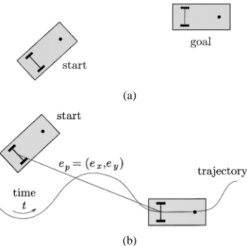
Fig. 1. Basic motion tasks for a WMR. (a) Point-to-point motion. (b) Trajectory following.
controllers, highlighting potential implementation problems re-lated to kinematic or dynamic nonidealities, e.g., wheel slip-page, discretization and quantization of signals, friction, back-lash, actuator saturation, and dynamics. This is to be regarded as a contribution in itself: in fact, while comparative simulations of control methods are given in [20] for a unicycle and in [21] for a car-like vehicle, an extensive experimental testing on a single benchmark vehicle was absent in the literature so far.
This paper is organized as follows. In Section II, we classify the basic control tasks for a WMR. Modeling and control prop-erties are summarized in Section III, where linearization via dy-namic feedback is mainly discussed. In Section IV, the experi-mental setup used in our tests is described in detail.
After discussing the generation of feedforward commands (Section V-A), a trajectory tracking controller based on feed-back linearization is described in Section V-B. Experimental results of tracking an eight-shaped trajectory are presented in Section V-C; the performance of the method is compared with that of a linear and a nonlinear controller, respectively, designed via approximate linearization along the reference trajectory and via Lyapunov analysis.
The use of dynamic feedback linearization for solving posture stabilization problems is studied in Section VI-A. Experimental results for forward and parallel parking tasks are reported in Section VI-B; for comparison, the same tasks are executed with three well-known controllers: a time-varying smooth feedback, a nonsmooth feedback, and a control law based on polar coor-dinates transformation.
Finally, in Section VII the obtained results are summarized and compared in terms of performance, ease of parameters tuning, sensitivity to nonidealities, and generalizability to other WMRs. In this way, guidelines are proposed to end-users interested in implementing control laws for WRMs. Open problems for further research are pointed out.
II. BASICMOTIONTASKS
The basic motion tasks that we consider for a WMR in an obstacle-free environment are (see Fig. 1) the following.
• Point-to-point motion: A desired goal configuration must be reached starting from a given initial configuration.
Fig. 2. Relevant variables for the unicycle (top view).
• Trajectory following: A reference point on the robot must follow a trajectory in the Cartesian space (i.e., a geometric path with an associated timing law) starting from a given initial configuration.
Execution of these tasks can be achieved using either feedfor-ward or feedback control (or a combination of the two); obvi-ously, the latter is to be preferred in view of its intrinsic degree of robustness. When executed under a feedback strategy, the point-to-point motion task leads to a regulation control problem for a point in the robot state space—posture stabilization is the expression used in this paper. Without loss of generality, the goal can be taken as the origin of the -dimensional robot configu-ration space.
Instead, trajectory following leads naturally to a tracking problem, which may be asymptotic in the presence of an initial error (i.e., an off-trajectory start for the vehicle). In the following, the term trajectory tracking will be adopted,
referring to the problem of stabilizing to zero ,
the two-dimensional Cartesian error with respect to the position of a moving reference robot [see Fig. 1(b)].
The design of posture stabilization laws for nonholonomic systems has to face a serious structural obstruction, that will be discussed in Section III. As a consequence, opposite to the usual situation, tracking is easier than regulation for a nonholonomic WMR. An intuitive explanation of this can be given through a comparison between the number of inputs and outputs. For the unicycle-like vehicle introduced in Section III, two input com-mands ( and ) are available, while three variables ( , , and ) are needed to determine its configuration. Thus, regulation of the WMR posture to a desired configuration implies zeroing three independent configuration errors. When tracking a trajec-tory, instead, the output has the same dimension as the input and the control problem is square.
III. MODELING ANDCONTROLPROPERTIES
Let be the -vector of generalized coordinates for a wheeled mobile robot. Pfaffian nonholonomic systems are char-acterized by nonintegrable linear constraints on the gen-eralized velocities. For a WMR, these arise from the rolling without slipping condition for the wheels.
The simplest model of a nonholonomic WMR is the unicycle, i.e., a single upright wheel rolling on the plane (top view in Fig. 2). The generalized coordinates are
( ). The constraint that the wheel cannot slip in the lateral direction is
By expressing all the feasible velocities as a linear combination of vector fields spanning the null space of matrix , one obtains the so-called first-order kinematic model
(1)
where and (respectively, the linear velocity of the wheel and its angular velocity around the vertical axis) are taken as control inputs ( ). As we will show in Section IV, this model is equivalent to that of SuperMARIO.
The driftless nonlinear system (1) has several control proper-ties, most of which actually hold for the whole class of WRMs and nonholonomic mechanisms in general.
A. Controllability and Stabilizability at a Point
The approximate linearization of (1) at any point is clearly not controllable. Hence, a linear controller cannot achieve posture stabilization, not even locally. However, denoting by the Lie bracket of and , it is easy to verify that the accessibility rank condition [22]
rank (2)
is globally satisfied. As the system is driftless, this guarantees its controllability—although in a nonlinear sense.
A severe limitation on the point stabilizability of system (1) is that Lyapunov stability cannot be achieved by using smooth (in fact, even continuous) time-invariant feedback laws. This neg-ative result is established on the basis of a necessary condition due to Brockett [23]: smooth stabilizability of a driftless regular system (i.e., such that the input vector fields are well defined and linearly independent at ) requires a number of inputs equal to the number of states. As a consequence, to obtain a posture sta-bilizing controller it is either necessary to give up the continuity requirement and/or to resort to time-varying control laws. B. Controllability and Stabilizability About a Trajectory
Given a desired Cartesian motion for the unicycle, many tracking methods require the generation of the corresponding
state trajectory and control inputs
(see Section V-A). In order to be feasible, the former must satisfy the nonholonomic constraint on the vehicle motion, that is, be consistent with (1).
Assume that the approximate linearization of (1) is computed about . Since the linearized system is time-varying, a nec-essary and sufficient controllability condition is that the control-lability Gramian is nonsingular. Although we do not give details here, it is relatively easy to show that such condition is indeed
satisfied as long as or ; this implies that smooth
stabilization is possible and, in particular, linear design tech-niques can be used to achieve local stabilization for arbitrary feasible trajectories, as long as they do not come to a stop.
C. Static Feedback Linearizability
The nonholonomic kinematic model (1) cannot be trans-formed into a linear controllable system using static (i.e., time-invariant) state feedback. In fact, the controllability condition (2) means that the distribution generated by vector fields and is not involutive, thus violating the necessary condition for full state feedback linearizability [22].
However, system equations can be transformed via feed-back into simple integrators (input–output linearization and de-coupling). The choice of the linearizing outputs is not unique. An interesting example is the following.
For the kinematic model (1), the globally defined coordinate transformation
and static state feedback
(3) lead to the so-called (2, 3) chained form
(4)
with and as linearizing outputs. Note that is the
unicycle position in a rotating left-handed frame having the axis aligned with the vehicle orientation (see Fig. 2).
More in general, it is known [24] that a two-input driftless nonholonomic system with states can always be trans-formed in chained form by static feedback, while for a set of necessary and sufficient conditions is available. In prac-tice, most WMR kinematic models can be put in chained form; a notable exception is the car–trailer system with two or more trailers hitched at some distance from the midpoint of the pre-vious wheel axle.
D. Dynamic Feedback Linearizability
For exact linearization purposes, one may also resort to dy-namic state feedback [6], [7]. In this case, the conditions for full state linearization are less stringent and are satisfied for a large class of nonholonomic WMRs (e.g., those transformable in chained form), including the unicycle.
With reference to a generic driftless nonlinear system (5) the dynamic feedback linearization problem consists in finding, if possible, a feedback compensator of the form
(6)
with state and input , such that the closed-loop
system (5) and (6) is equivalent, under a state transformation , to a linear system. Only necessary or sufficient
(but no necessary and sufficient) conditions exist for the solution of this problem. Constructive algorithms are essentially based on input-output decoupling [22].
The starting point is the definition of an -dimensional output , to which a desired behavior can be assigned. One then proceeds by successively differentiating the output until the input appears in a nonsingular way. At some stage, the addition of integrators on some of the input channels may be necessary to avoid subsequent differentiation of the original inputs. This dynamic extension algorithm builds up the state of the dynamic compensator (6). If the system is invertible from the chosen output, the algorithm terminates after a finite number of differentiations. If the sum of the output differentiation orders equals the dimension of the extended state space, full input–state–output linearization is obtained.1 The closed-loop system is then equivalent to a
set of decoupled input–output chains of integrators from to .
We illustrate this exact linearization procedure for the uni-cycle model (1). Define the linearizing output vector as
. Differentiation with respect to time then yields
showing that only affects , while the angular velocity cannot be recovered from this first-order differential informa-tion. To proceed, we need to add an integrator (whose state is denoted by ) on the linear velocity input
being the new input the linear acceleration of the unicycle. Differentiating further, we obtain
and the matrix multiplying the modified input is nonsin-gular if . Under this assumption, we define
so as to obtain
(7) The resulting dynamic compensator is
(8)
Being , it is , equal to the output
differentiation order in (7). In the new coordinates
1In this case, is also called a flat output [25].
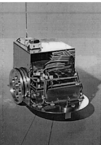
Fig. 3. WMR SuperMARIO.
(9) the extended system is, thus, fully linearized and described by the two chains of integrators in (7), rewritten as
(10) The dynamic compensator (8) has a potential singularity at , i.e., when the unicycle is not rolling. The occur-rence of such singularity in the dynamic extension process is structural for nonholonomic systems [6]. This difficulty must be obviously taken into account when designing control laws on the equivalent linear model.
IV. TARGETVEHICLE: SUPERMARIO
The experimental validation of the proposed control method and its comparison with existing controllers has been performed on our prototype SuperMARIO (Fig. 3).
A. Physical Description
SuperMARIO is a two-wheel differentially driven vehicle. The wheels have a radius of cm and are mounted on an axle cm long. The wheel radius includes the o-ring used to prevent slippage; the rubber is stiff enough that point con-tact with the ground can be assumed. A small passive caster is placed in the front of the vehicle at 29 cm from the rear axle. The
aluminum chassis of the robot measures 46 32 cm
(l/w/h) and contains two motors, transmission elements, elec-tronics, and four 12-V batteries. The total weight of the robot is about 20 kg and its center of mass is located slightly in front of the rear axle. This design limits the disturbance induced by sudden reorientation of the caster. Each wheel is driven by an MCA dc servomotor supplied at 24 V with a peak torque of 0.56 Nm. Each motor is equipped with an incremental encoder
counting pulses/turn and a gearbox with reduction
ratio . On-board electronics multiplies by a factor the number of pulses/turn, representing angular increments with 16 bits.
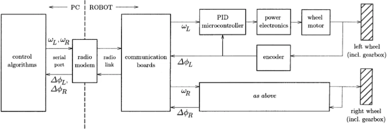
Fig. 4. Control architecture of SuperMARIO.
SuperMARIO is a low-cost prototype and presents, therefore, the typical nonidealities of electromechanical systems, namely friction, gear backlash, wheel slippage, actuator deadzone, and saturation. These limitations clearly affect the control perfor-mance.
B. Control System Architecture
SuperMARIO has a two-level control architecture (see Fig. 4). High-level control algorithms (including reference motion generation) are written in C and run with a sampling
time of ms on a remote server (a 300-MHz Pentium
II), which also provides a user interface with real-time visual-ization and a simulation environment. The PC communicates through a radio modem with serial communication boards on the robot. The maximum speed of the radio link is 4800 b/s. Wheel angular velocity commands and are sent to the
robot and encoder measures and are received for
odometric computations.
The low-level control layer is in charge of the execution of the high-level velocity commands. For each wheel, an eight-bit ST6265 microcontroller implements a digital PID with a cycle time of ms. Two power amplifiers drive the motors with a 51-KHz PWM voltage.
Custom interpolation algorithms were developed on the PC to reduce the effect of quantization errors and communication delays in the reconstruction of the robot posture from the odometric data. Additional filtering of high-level velocity commands is included to account for vehicle and actuator dynamics: simple first-order linear filters smooth possible discontinuities in the velocity profiles.
C. Kinematics
The kinematic model of SuperMARIO is given by (1), i.e., is equivalent to that of a unicycle. However, the actual commands are the angular velocities and of the right and left wheel, respectively, rather than the driving and steering velocities and . There is, however, a one-to-one mapping between these velocities
(11)
A calibration procedure has also been developed to estimate the actual wheel radii and axle length.
The reconstruction of the current robot configuration is based
on incremental encoder data (odometry). Let and be
the angular wheel displacements measured during the sampling time by the encoders. From (11), the robot linear and angular displacements are
The posture estimated at time is
(12)
where2 . Robot localization using the above
odometric prediction (commonly referred to as dead reckoning) is quite accurate in the absence of wheel slippage and backlash. These effects are largely reduced when the velocity is kept rea-sonably small and the number of backup maneuvers is limited. D. Control Constraints
In view of the bounded velocity of the motors, each wheel can achieve a maximum angular velocity . Through (11), the bounds on driving and steering velocities are
There is, however, a more stringent constraint due to the lim-ited resolution of the digital low-level control layer. In fact, the linear displacement resolution of the robot can be com-puted from the previous data as
cm This value corresponds to the least significant bit of the encoder, so that the average quantization error will be less than 0.02 mm. In view of the eight-bit resolution of the on-board velocity mi-crocontroller and of the PWM circuit (having
2The use of the average value of the robot orientation is equivalent to the
Hz as minimum pulse frequency), the actual linear velocity command has the following threshold and saturation levels:
cm/s cm/s
To prevent as much as possible wheel slippage, in our control software we have imposed even more conservative bounds on high-level velocity commands
m/s rad/s
In view of these saturations, we perform a velocity scaling so as to preserve the curvature radius corresponding to the nominal
velocities and . The actual commands and are then
computed by defining
and letting
sign if
sign if
if
This procedure implements a low-level post-processing of the outputs of any controller implemented on SuperMARIO. Since the curvature of the Cartesian path is locally preserved, this will not affect the correct execution of regulation tasks, while it may prevent perfect trajectory tracking. On the other hand, this is per-fectly reasonable, since it will only happen when the reference trajectory is not compatible with the vehicle velocity bounds.
V. TRAJECTORYTRACKING
The solution of the tracking problem requires the combina-tion of a nominal feedforward command with a feedback accombina-tion on the error. In the control scheme to be presented, this error will be defined with respect to the reference output trajectory (output error). In other tracking controllers, such as those used for comparison in Section V-C, the tracking error is defined with respect to the reference state trajectory associated to the output trajectory (state error).
A. Feedforward Command Generation
Assume the representative point of the unicycle must
follow the trajectory , for (possibly,
). From the kinematic model, (1) one has
ATAN2 (13)
where ATAN2 is the four-quadrant inverse tangent function (un-defined only if both arguments are zero). Therefore, the nominal feedforward commands are
(14) (15) having differentiated (13) with respect to time in order to com-pute . The chosen sign for will determine forward or
backward motion of the vehicle. In order to be exactly
repro-ducible using and , the desired Cartesian motion
should be twice differentiable in .
A remarkable property of the unicycle is that, given an initial posture and a consistent output trajectory , there is a unique associated state
trajec-tory , which can be computed
in an algebraic way—a consequence of being a
linearizing output under dynamic feedback. In fact, we have
ATAN2 (16)
where is chosen so that , being the initial value
of the orientation. If , a backward motion will result. Hence, if needed by the tracking control scheme, the nominal orientation may be computed off-line.
Note the following facts.
• When the desired linear velocity is zero for some , nei-ther nor are defined from (15) and (16), respec-tively. This may occur at the initial instant, if a smooth start is specified, or at a cusp along the geometric path underlying
the trajectory . In the first case, one can use
higher order differential information about at
to determine the consistent initial orientation and an-gular velocity command. For the second case, continuous motion is guaranteed by keeping the same orientation at-tained at ; by using de L’Hôpital analysis in (15), one can
also compute .
• More in general, the reference trajectory may be specified by separating the geometric aspects of the path
(parameter-ized by a scalar ) from the timing law used for
path execution. The driftless nature of the kinematic model of a WMR allows to overcome in this way the above “zero velocity” problem. For the unicycle, we can rewrite purely geometric relationships as
where time commands are recovered as ,
. Zero-velocity points with well-defined tangent (e.g., cusps) are obtained for . The
feed-forward pseudo-velocities and are computed by
replacing time with space derivatives in (14) and (15). B. Feedback Design
A nonlinear controller for output trajectory tracking based on dynamic feedback linearization is easily devised. Assume the
robot must follow a smooth trajectory which is
persistent, i.e., such that the nominal control input
along the trajectory never goes to zero. On the equivalent linear and decoupled system (10), it is straightforward to design an exponentially stabilizing feedback for the desired trajectory (with linear Cartesian transients) as
with proportional-derivative (PD) gains chosen as , , for . These signals should be fed to the dy-namic compensator (8) in order to obtain the actual control in-puts.
The above result is valid provided that the dynamic feedback
compensator (8) does not meet the singularity . In
view of the persistency of the reference trajectory, this may only happen during the initial transient of an asymptotic tracking problem. Below, we give sufficient conditions under which the singularity does never occur.
Theorem 1: Let and be, respectively, the eigenvalues of the closed-loop dynamics of the two tracking error components
Assume that, for , it is (negative real
eigenvalues) and sufficiently small. If
(18)
with and , then the singularity
is never met. Proof: Being
the singularity is avoided if
(19) Using the solution of the closed-loop error dynamics
where the constants depend on the initial conditions
and on the chosen eigenvalues, a tedious but simple analysis shows that the norm of the velocity error is upper bounded by
its value at , provided that , , is sufficiently
small. From this fact and (19), the thesis follows.
Note that the left-hand side of (18) is always positive due to the persistency of the reference trajectory. Hence, in order to apply Theorem 1, one must 1) choose the PD gains so as to sat-isfy the assumption on and and 2) select, if possible, an initial value for the dynamic compensator state that satisfies condition (18), where
As a matter of fact, the existence of a suitable is guaranteed under the additional sufficient condition
(20)
In fact, in this case one may easily check that letting
the following is automatically satisfied:
We emphasize that the sufficient condition (20) can be always enforced through a suitable velocity scaling procedure along the reference path. Clearly, this will not affect the asymptotic tracking of the original reference trajectory as long as the scaled trajectory approaches the latter as .
We conclude the discussion on trajectory tracking via dy-namic feedback linearization with some remarks.
• Instead of resorting to the above sufficient conditions for sin-gularity avoidance, one may envisage a more naive solution that consists in resetting the state of the compensator when-ever its value falls below a given threshold. This strategy results in a bounded velocity input with isolated discon-tinuities with respect to time, which in our implementation will be, however, smoothed out by the linear filters (see Sec-tion IV-B).
• To obtain exact trajectory tracking for a matched initial
pos-ture of the robot, i.e., , and (or
), the dynamic compensator should be correctly
initialized at (or ).
• Being based on the output tracking error, this method does not require the explicit computation of .
• The PD control law (17) requires the velocities and . To compute these, there are two possible options, both based on the availability of the robot posture as reconstructed from the odometry: either use the state of the dynamic com-pensator together with the last two rows in (9), or numerically
differentiate [with the increments directly
provided by the odometric sensors]. In ideal conditions, the two solutions are equivalent, whereas the second is expected to be more robust with respect to unmodeled dynamics. C. Experiments
We now report experimental results of SuperMARIO tracking the eight-shaped trajectory of Fig. 5, defined by
The trajectory starts from the origin with rad; this information is not needed by the dynamic feedback linearizing controller, but it is needed to generate in the two other tracking controllers used for comparison [see (21) and (22)].
The initial velocities are m/s, rad/s.
A full cycle is completed in s.
To assess the performance of the feedback linearization controller, we also present experimental results of two state tracking methods. The first is obtained by performing a preliminary change of inputs in the unicycle model, then approximately linearizing the error dynamics with regard to the reference trajectory, and finally imposing a desired closed-loop characteristic polynomial with a simple linear design for the
Fig. 5. Eight-shaped reference trajectory.
transformed control inputs. In terms of the original control inputs, this leads to the following equations:
sign
(21) A convenient choice (see [20] for details) of the gains is
with , .
The second tracking controller is the outcome of a nonlinear design based on an appropriate Lyapunov function [9]
(22) Inspired to the previous linear design, one can choose the gain functions and and the constant gain as
In the first set of experiments, the robot starting configura-tion is matched with the reference trajectory [i.e., ]. Figs. 6–8 show the results obtained by the dynamic feedback
linearization controller (8)–(17), with ,
and . Here, as in all the experiments,
, and are reconstructed from encoder data using the odo-metric model (12), while and are the reference velocities computed by the controller. The tracking of the reference trajec-tory is very accurate; residual errors are mainly due to quantiza-tion and discretizaquantiza-tion of velocity commands. Note that the de-sired Cartesian trajectory is followed with the robot in forward
Fig. 6. Trajectory tracking via dynamic feedback linearization:x (0 0), y (0 1) (m), and (—) (rad) versus time (s).
Fig. 7. Trajectory tracking via dynamic feedback linearization: driving velocityv (m/s).
Fig. 8. Trajectory tracking via dynamic feedback linearization: steering velocity! (rad/s).
Fig. 9. Trajectory tracking via dynamic feedback linearization: norm of Cartesian error (m).
Fig. 10. Trajectory tracking with linear feedback design: norm of Cartesian error (m).
motion. The achieved performance can be compared with those
of the other two controllers (both with and )
looking at Figs. 9–11, which show for each case the norm of the Cartesian error, obtained using the reconstructed , and the reference , . Note in Fig. 10 the large transient error in-duced by the vehicle/actuator dynamics in the presence of an ini-tial nonzero value of . Both the feedback linearization and the nonlinear design controller are more effective in reducing this error. On the whole trajectory, the mean value of the error ranges from 1 cm (linear design) to 0.5 cm (nonlinear design) and to 0.38 cm (feedback linearization design).
A second set of experiments was performed letting (m, m, rad), i.e., starting with an initial state error with respect to the assigned trajectory (asymptotic tracking). Only the linearly designed controller and the dy-namic feedback controller were compared (see Figs. 12 and 13), using the same control parameters as before. The obtained transients are quite similar, although a smaller overshoot is
Fig. 11. Trajectory tracking with nonlinear feedback design: norm of Cartesian error (m).
Fig. 12. Asymptotic trajectory tracking via dynamic feedback linearization: Cartesian errorse and e (m).
Fig. 13. Asymptotic trajectory tracking with linear feedback design: Cartesian errorse and e (m).
experienced with dynamic feedback linearization, as implied by the choice of the PD gains.
VI. POSTURESTABILIZATION
As mentioned in Section III, point stabilization of nonholo-nomic WMRs cannot be achieved by smooth static feedback. Below, we show that the tracking scheme (8)–(17) based on dy-namic linearization provides a discontinuous controller that is effective for posture stabilization, and compare its performance with three existing controllers.
A. Feedback Design
To extend the tracking controller based on feedback lineariza-tion to the posture stabilizalineariza-tion problem one must avoid the sin-gularity not only during the transient (as in the trajec-tory tracking case) but also asymptotically, i.e., as the robot ap-proaches the final destination. Again, this simply requires an appropriate choice of the PD gains and a suitable initialization of the dynamic compensator state .
Assume w.l.o.g. that the origin is the desired final posture, and denote by
OR OR
a subset of which will require special attention. The remaining part of the configuration space can be parti-tioned in two regions
Theorem 2: Consider the unicycle system (1) under the
ac-tion of dynamic compensator (8). Setting in the
PD control law (17), i.e., choosing
(23) yields exponential convergence from any starting configuration
to the origin, under the following assumptions.
A1. Gains , ( ) satisfy the conditions (24) (25)
A2. The initial state of the compensator is chosen as (backward motion) if
(forward motion) if
but its value is otherwise arbitrary, except for the additional con-dition
(26)
Proof: Use of control (23) in (10) implies that coordinates and converge to zero exponentially, provided that the orig-inal control inputs and given by (8) remain bounded. To show this, we must prove that 1) does not go to zero in finite time, and 2) tends to zero for , in spite of its denomi-nator vanishing.
1) Since from (9) it is , one has iff
, for a generic . Integrating the closed-loop system (10) under control (23), we have
(27) (28) where eigenvalues and coefficients are functions of initial state and PD gains
From these expressions and condition (24), it is easy to show
that a finite such that exists iff
with . From this, a quadratic equation
in is derived which has the single nonzero root
Once rewritten in terms of the PD gains, this expression leads to the forbidden initialization condition (26).
2) Assumption A1 implies that the eigenvalues are real and
ordered as . From (8), we
rewrite as
and using (23), (27), and (28), the numerator of takes the form
with . Its asymptotic convergence rate is larger than due to the eigenvalue ordering. As for the denomi-nator, squaring and adding (27) and (28) gives
with . Since the asymptotic rate of convergence of this quantity is exactly , we conclude that tends exponentially to zero as .
To finish the proof, consider the following facts.
• The unicycle reaches the origin with a horizontal tangent
( or ), because approaches zero faster than in
view of the eigenvalue ordering.
• Motion inversions do not occur since never crosses zero, as shown in the first part of the proof.
• The trajectory is confined to the region (either or ) from which the unicycle starts. In fact, and never change sign because the eigenvalues are real and thanks to the choice of sign for in assumption A2.
Their immediate consequence is that also the orientation converges to zero. As for its rate of convergence, it is exponen-tial in view of the fact that the derivative of converges ex-ponentially to zero.
Some remarks are needed at this point.
• As the Cartesian position transients are linear, the unicycle trajectories obtained with the proposed controller are com-pletely predictable and can be easily shaped by choosing the PD control gains. Note that the unicycle can reach the goal either with a forward or with a backward motion.
• The equality part of condition (24) in Theorem 2 is by no means necessary; it is only used for deriving a closed form for the forbidden initialization (26) of the dynamic compen-sator. Other choices are possible and will lead to different forbidden initializations. The inequality part of the same con-dition implies that the eigenvalues that characterize the tran-sient are real, so that no oscillations are experienced during the approach to the destination.
• In view of the discontinuity at the origin of the linearizing
controller with respect to the state of the
ex-tended system, as well as of the fact that the initial configu-ration should belong to , the proposed feedback con-troller does not yield Lyapunov stability in a strict sense, but simply exponential convergence.
If the initial configuration belongs to , Theorem 2 cannot be applied. In fact, control (23) would bring the unicycle to the origin with the wrong orientation, namely, if
, if , if ,
and if . In such a situation, it is necessary to
reset the compensator state at some time , so as to invert
the motion at a configuration . A simple way to
obtain this is to introduce a via point
in the regulation procedure, as illustrated below by the parallel parking experiment. Convergence to the origin is then obtained in two phases: in the first, is the desired setpoint, and converges exponentially to based on Theorem 2. Thus, in a finite predictable time will enter a sufficiently small
neighborhood of contained in , where the second phase can be safely started by resetting the setpoint to the origin.
Clearly, the choice of will affect the shape of the generated path. For example, in the case , a reasonable strategy is
to set , , , which yields a
symmet-rical maneuver spanning equal lengths on both and axes. The necessity of adding a via point when belongs to does not necessarily represent a drawback of the method; a suitable choice of the via point allows better control of the path shape while approaching the goal configuration. In particular, the re-sulting stabilization motion contains at most one backup ma-neuver. With this modification, our method guarantees global exponential convergence of the vehicle to the desired configu-ration.
B. Experiments
To show the performance of the feedback linearization con-troller (23) for posture stabilization, we report the results of Su-perMARIO executing first a forward parking task from
(m, m, rad) to the origin. For comparison, we also executed the same task with three additional posture stabilizing controllers.
The first [9] is a smooth time-varying feedback control, which has exactly the same structure of the trajectory tracking con-troller (22). To achieve posture stabilization, however, the ref-erence signals (state trajectory and control inputs) must be ap-propriately chosen. One possibility is to set, for all , ,
[and thus ] and
with an auxiliary error vector and a so-called heating function
We also implemented on SuperMARIO a nonsmooth time-varying feedback [13] designed on the chained form (4). The control law, designed on the basis of the backstepping principle, is nonsmooth with respect to the state, which is fed back only
at uniformly sampled instants. At ( ),
one lets
(29)
where , , and
with , and . Equation (29)
should be used in conjunction with (3) in order to generate the actual velocity inputs and .
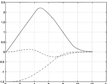
Fig. 14. Posture stabilization using dynamic feedback linearization (forward parking):x (– –), y (–1) (m), and (—) (rad) versus time (s).
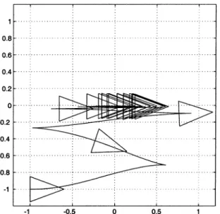
Fig. 15. Posture stabilization via dynamic feedback linearization (forward parking): Cartesian motion(x; y) (m).
The third posture stabilizing controller used for comparison overcomes the obstruction of Brockett condition for smooth sta-bilizability by applying a change of coordinates such that the input vector fields of the transformed equations are singular at the origin [12]. In particular, defining the polar coordinate trans-formation
ATAN2
a Lyapunov-like technique is used to design the following con-trol law:
(30) with and positive constants. Also this feedback, once rewritten in terms of the original state variables, is discontin-uous at the origin of the configuration space .
Fig. 16. Posture stabilization via dynamic feedback linearization (forward parking): driving velocityv (m/s).
Fig. 17. Posture stabilization via dynamic feedback linearization (forward parking): steering velocity! (rad/s).
For all controllers, the accuracy in regulation to the origin is determined by the satisfaction of the following terminal bounds:
cm cm rad
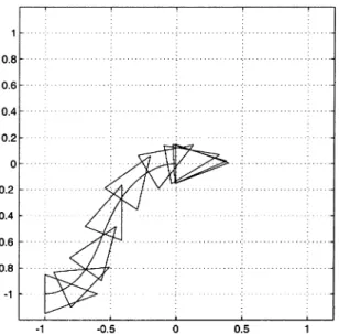
Figs. 14–17 refer to the results of the dynamic feedback lin-earization controller (23) with gains chosen as ,
, , , and compensator initialization
(m/s). The convergence to the goal is fast and very natural, as shown in Fig. 15, a stroboscopic view of the robot motion sampled every 1.5 s. Note that saturation occurs on both inputs during the transient phase.
The performance of the smooth time-varying controller is
shown in Fig. 18. The gains have been set to , ,
, , and , while has been initialized
at . After a relatively fast approach, the convergence becomes extremely slow when the unicycle is close to the goal. In particular, this is evident in Fig. 19, a stroboscopic view of the robot motion sampled every 10 s. An inherent limitation of
Fig. 18. Posture stabilization with smooth time-varying feedback (forward parking):x (– –), y (–1) (m), and (—) (rad) versus time (s).
Fig. 19. Posture stabilization with smooth time-varying feedback (forward parking): Cartesian motion(x; y) (m).
this control design is the large number of backup maneuvers, executed with the unicycle approximately aligned with the final desired orientation.
Fig. 20 displays the outcome of the application of the control
law (29), with s, , and . The
rate of convergence of the nonsmooth time-varying controller is somewhat improved but still quite slow. A stroboscopic view of the unicycle motion sampled every 5 s is reported in Fig. 21. Note that the approach in the direction is very uniform, while maneuvers in the vicinity of the goal are aimed at adjusting rather than . This is intrinsic in the structure of the chained form used for the control design.
Finally, the results obtained with the polar coordinates
con-troller (30), with gains , , and , are reported
in Fig. 22. The convergence to the goal is very fast and natural. In Fig. 23, a stroboscopic view of the unicycle motion sampled every 1 s is given.
Fig. 20. Posture stabilization with nonsmooth time-varying feedback (forward parking):x (– –), y (–1) (m), and (—) (rad) versus time (s).
Fig. 21. Posture stabilization with nonsmooth time-varying feedback (forward parking): Cartesian motion(x; y) (m).
Fig. 22. Posture stabilization using feedback in polar coordinates (forward parking):x (– –), y (–1) (m), and (—) (rad) versus time (s).
Fig. 23. Posture stabilization using feedback in polar coordinates (forward parking): Cartesian motion(x; y) (m).
Fig. 24. Posture stabilization via dynamic feedback linearization (parallel parking):x (– –), y (–1) (m), and (—) (rad) versus time (s).
We also executed a parallel parking from
(m, m, rad) to the origin. The results obtained with the feedback linearization controller (23) are shown in Fig. 24–27. As
, a via point (m, m, rad) has been added.
The PD gains are the same as before, while the compensator state initialization is chosen here as for the first
phase, performed in backward motion, and for
the second phase, which is started in a neighborhood of and performed in forward motion. The simple first-order linear filter introduced to account for actuator dynamics is also effective in smoothing the discontinuity in the driving velocity generated by the reset procedure. On the other hand, the presence of the same filter for the steering velocity, coupled with the software velocity saturation, neutralizes the effect of the singularity in due to the zero crossing of the filtered driving velocity.
For comparison, we have executed a similar experiment with the polar coordinates controller (30), using the same gains as before; here, the starting configuration is chosen as
Fig. 25. Posture stabilization via dynamic feedback linearization (parallel parking): Cartesian motion(x; y) (m).
Fig. 26. Posture stabilization via dynamic feedback linearization (parallel parking): driving velocityv (m/s).
Fig. 27. Posture stabilization via dynamic feedback linearization (parallel parking): steering velocity! (rad/s).
Fig. 28. Posture stabilization using feedback in polar coordinates (parallel parking):x (– –), y (–1) (m), and (—) (rad) versus time (s).
Fig. 29. Posture stabilization using feedback in polar coordinates (parallel parking): Cartesian motion(x; y) (m).
(m, m, rad). The performance is shown in Fig. 28 and 29 and indicate that there is no backup maneuver in this case. If the robot had been initially closer to the positive axis, this control law would have automatically driven the robot backward and then in forward motion to the goal. This is a general property of controller (30): in the final phase, the vehicle will always approach the goal in forward motion, having executed at most one backup maneuver. Finally, note that the behavior of the controlled system is not continuous with respect to the initial state. For example, assume that the
initial configuration is , and .
Positive and negative arbitrarily small values of will lead to different transient motions to the goal (in fact, symmetric with respect to the axis).
VII. GUIDELINES FOREND-USERS A. Summary and Comparison
We have performed several motion tasks with SuperMARIO using the proposed control law based on feedback linearization
as well as the other controllers. The experimental tests presented in this paper are representative of the average performance of the controllers. We summarize our acquired experience in general observations that can be useful guidelines for implementation of the same control strategies on other vehicles.
First, the computational load for all methods is quite similar in the case of the unicycle. Basically, both trajectory tracking and posture stabilization controllers can be implemented with on-board computing power. Our choice of separating high-level control routines, performed on a remote server, from low-level control loops in charge of realizing the reference velocity com-mands reflects the choice of a modular structure. Such decom-position is expected become even more convenient for WMRs with more complex kinematics, such as a tractor vehicle towing trailers.
All the implemented trajectory tracking methods can be generalized to more complex vehicles, provided their models are transformable in chained form. Such generalizations can be found in [10] and [21]. From the point of view of control parameters tuning, especially for more complex WMRs, the dynamic feedback linearization technique appears to be simpler since it boils down to the choice of stabilizing gains for a chain of integrators; in any case, it can be always carried out on the original equations without resorting to the transformation in chained form.
In Table I, posture stabilization controllers are compared in terms of performance, ease of parameter tuning, sensitivity to nonidealities, generalizability to more complex WMRs, and re-lation with tracking controllers.
Time-varying controllers, both smooth and nonsmooth, ex-hibit a rather slow convergence to the goal. In general, the non-smooth controller should behave better due to its exponential rate of convergence, but the dependence of this rate on the con-trol gains is critical. The oscillatory behavior of the vehicle during the approach to the goal, which makes the motion er-ratic, is an intrinsic characteristic of both time-varying control laws. The presence of several motion inversions makes these methods sensitive to mechanical nonidealities (e.g., backlash) of the wheels, and may introduce a remarkable difference be-tween the movement computed from the odometry and the ac-tual vehicle displacement. In our experience, this behavior was confirmed also in experiments performed with a car-like vehicle (the MARIO robot [26]), where a nonnegligible backlash on the steering angle of the front wheels led to a substantial error in the final positioning. Another potential problem with the presented nonsmooth controller is that, being based on a low-rate sampled state feedback [see (29)], the robot could in principle “miss” the final goal even if passing through it. A positive feature of time-varying control laws is that they can readily be general-ized to any WMR allowing a chained-form representation [10], [13].
The controller based on polar coordinates transformation per-formed very well. The resulting vehicle path is very natural (in the sense that is similar to that followed by an experienced human driver) and convergence is quite fast, with a weak depen-dence on the choice of the few control gain parameters. Since at most one backup maneuver is needed, disturbances due to
TABLE I
A COMPARISON OF THEPOSTURESTABILIZATIONCONTROLLERSIMPLEMENTED ONSUPERMARIO
wheel backlash are minimized. Unfortunately, a direct exten-sion of such controller is not yet available for vehicles with more complex kinematics. The idea of using a state-space transforma-tion that is singular at the goal configuratransforma-tion, however, stands on its own and has been exploited by other researchers, e.g., in [27]. Similar positive comments can be drawn on the performance of the posture stabilization method designed via dynamic feedback linearization. In particular, this scheme allows par-allel parking with backward–forward motion, which is a very natural maneuver. The control tuning requires the choice from a very large feasible set of PD gains. The relationship with the analogous controller for trajectory tracking is very simple: it is sufficient to add the feedforward terms, i.e., the reference output position, velocity, and acceleration [compare (17) with (23)].
As for the use of an additional dynamics within the control law, it has pros and cons. On one side, this design compensates for the use of a first-order kinematic model of the unicycle, by bringing linear acceleration into the picture. On the other side, it is necessary to prevent zeroing of the compensator state and the consequent singularity of the control commands; this may be guaranteed by enforcing additional conditions (such as those of Theorem 1 for tracking and of Theorem 2 for stabilization) or may be achieved in practice by resetting the compensator state whenever its value falls below a given threshold. In our implementation, the simple strategy of filtering plus saturating the velocity commands keeps the actual commands bounded in any case.
The generalization to point-to-point motion tasks for WMRs with more complex kinematics is under way. It basically con-sists in extending the idea of suitably shaping the transient be-havior on the linear side of the problem by appropriate selection of the gain structure (a PD for generalized coordinates), so as to achieve a smooth and correct “entrance” into the goal for the two outputs representing the robot Cartesian position.
All the controllers mentioned in this paper use a measure of the state reconstructed on the basis of the robot odometry.
In principle, the actual motion of SuperMARIO on the ground may be quite different and should be computed with the aid of exteroceptive sensors. However, in our experiments, this difference was not visually appreciable, as shown by the videos on the web page http://labrob.ing.uniroma1.it/projects/ram-sete.html. The satisfactory performance of dead reckoning localization is of course related to the execution of relatively slow motions.
A final remark is needed about the application of the control methods of this paper when workspace obstacles are present. In a completely known environment, it may be convenient to tackle the navigation problem of a WMR using a three-layer control structure. The highest layer is devoted to motion planning and takes care of the nominal avoidance of obstacles; the nonholo-nomic motion constraints of the WMR may or may not be taken into account at this stage. The second layer takes charge of mo-tion execumo-tion and uses one of the trajectory tracking controllers given in this paper. In the vicinity of the goal, fine posture reg-ulation (docking) can be obtained at the lowest layer by means of one of the presented stabilizing controllers.
B. Future Directions
From an application viewpoint, there are some important is-sues that deserve further research.
Inclusion of dynamics. In this paper, the control problem—as very often done—has been addressed on the first-order kine-matic model of the unicycle. This situation should not only be regarded as a simplification of the problem: it also reflects the fact that the control architecture of our mobile robot (as with most robots and manipulators) does not allow the user to impose acceleration or torque inputs. As explained in Section IV-B, only the reference velocities , can be fed to the propor-tional-integral-derivative (PID) microcontrollers of the actua-tors. The linear velocity input imposed to the robot, which coincides with the state of the dynamic compensator, is used to compute , through (11). If the actual linear velocity of
the vehicle is different from (as it may be, particularly at the beginning of motion), it is the low-level PID control which will bring it to the value specified by the high-level control.
However, for massive vehicles and/or at high speeds, consid-eration of robot dynamics is necessary for realistic control de-sign. The dynamics of general nonholonomic systems is thor-oughly analyzed in [28] and, more specifically for WMRs, in [29]. Interestingly, nonlinear static state feedback can be used to cancel, in the nominal case, all inertial parameters so as to lead to the second-order kinematic model
(31)
with as the -dimensional state and acceleration
as the new control input. The control laws used in this paper do not directly apply to this case (they may have finite jumps in the velocity). However, we are currently working out an extension of the present approach, which can be sketched as follows.
Feedback linearization of model (31) for the unicycle requires again a one-dimensional dynamic controller, but leads to a closed-loop linear system consisting of two chains of three input–output integrators. As with the first-order model, the singularity may occur when the linear velocity of the vehicle (now a state variable) goes to zero at a finite time. For a trajec-tory tracking task, there is virtually no difference with respect to the theory presented here. For a posture stabilization task, using the linearizing coordinate and control transformations, one should seek conditions on the control gains of the linear controller (now a PD for each chain) so as to guarantee the correct relative rates of exponential convergence for the state variables, in such a way that does not go to zero in finite time and is always bounded (compare with the proof of Theorem 2).
Robust control design. Very few papers have addressed ro-bustness issues in the control of nonholonomic systems. Robust stabilization of WMRs in chained form was obtained in [30] and [31] by applying iteratively an open-loop command; exponen-tial convergence to the desired equilibrium is obtained for small perturbations in the kinematic model. Another solution to the regulation problem based on the backstepping framework was proposed in [32]. A conceptually different approach to the de-sign of effective control laws in the presence of nonidealities and uncertainties is represented by learning control, as shown in [26]. We also note that perturbations acting on nonholonomic mobile robots are not of equal importance: a deviation in a di-rection compatible with the vehicle mobility is clearly not as severe as a deviation which violates the kinematic constraints of the system (e.g., lateral sliding).
Use of exteroceptive feedback. Proprioceptive sensors, such as encoders, become unreliable in the presence of wheel slip-page. As a result, the robot may progressively “lose” itself in the environment. A solution is to close the feedback loop with exteroceptive sensors providing absolute information about the robot localization in its workspace; sensor fusion techniques are relevant at this stage. The design of sensory feedback for non-holonomic robots is at the beginning stage but growing fast. Preliminary results with visual feedback from a fixed camera system are described in [33].
WMRs not transformable in chained form. Among the open problems in controlling general WMRs, we mention the case of multibody vehicles that do not admit a transformation in chained form, such as a unicycle or car-like tractor with two or more trailers hitched at some distance from the midpoint of the pre-vious wheel axle. A possible approach to posture stabilization, using iterative steering of a nilpotent approximation model, can be found in [34].
ACKNOWLEDGMENT
The authors thank Prof. Giovanni Ulivi of the Università di Roma Tre for participating in the design of SuperMARIO.
REFERENCES
[1] J. L. Jones and A. M. Flynn, Mobile Robots: Inspiration to
Implementa-tion. Wellesley, MA: A. K. Peters, 1993.
[2] J. C. Alexander and J. H. Maddocks, “On the kinematics of wheeled mobile robots,” Int. J. Robot. Res., vol. 8, no. 5, pp. 15–27, 1989. [3] J. I. Neimark and F. A. Fufaev, Dynamics of Nonholonomic
Sys-tems. Providence, RI: Amer. Math. Soc., 1972.
[4] G. Campion, B. d’Andrea-Novel, and G. Bastin, “Modeling and state feedback control of nonholonomic mechanical systems,” in Proc. 30th
IEEE Conf. Decision Contr., Brighton, U.K., 1991, pp. 1184–1189.
[5] C. Samson and K. Ait-Abderrahim, “Feedback control of a nonholo-nomic wheeled cart in Cartesian space,” in Proc. 1991 IEEE Int. Conf.
Robot. Automat., Sacramento, CA, 1991, pp. 1136–1141.
[6] A. De Luca and M. D. Di Benedetto, “Control of nonholonomic systems via dynamic compensation,” Kybernetica, vol. 29, no. 6, pp. 593–608, 1993.
[7] B. d’Andrea-Novel, G. Bastin, and G. Campion, “Control of nonholo-nomic wheeled mobile robots by state feedback linearization,” Int. J.
Robot. Res., vol. 14, no. 6, pp. 543–559, 1995.
[8] Z.-P. Jiang and H. Nijmeijer, “A recursive technique for tracking con-trol of nonholonomic systems in chained form,” IEEE Trans. Automat.
Contr., vol. 44, pp. 265–279, Feb. 1999.
[9] C. Samson, “Time-varying feedback stabilization of car-like wheeled mobile robots,” Int. J. Robot. Res., vol. 12, no. 1, pp. 55–64, 1993. [10] , “Control of chained systems. Application to path following
and time-varying point-stabilization of mobile robots,” IEEE Trans.
Automat. Contr., vol. 40, pp. 64–77, Jan. 1995.
[11] C. Canudas de Wit and O. J. Sørdalen, “Exponential stabilization of mobile robots with nonholonomic constraints,” IEEE Trans. Automat.
Contr., vol. 37, pp. 1791–1797, Nov. 1992.
[12] M. Aicardi, G. Casalino, A. Bicchi, and A. Balestrino, “Closed loop steering of unicycle-like vehicles via Lyapunov techniques,” IEEE
Robot. Automat. Mag., vol. 2, pp. 27–35, 1995.
[13] O. J. Sørdalen and O. Egeland, “Exponential stabilization of nonholo-nomic chained systems,” IEEE Trans. Automat. Contr., vol. 40, pp. 35–49, Jan. 1995.
[14] R. T. M’Closkey and R. M. Murray, “Exponential stabilization of driftless nonlinear control systems using homogeneous feedback,”
IEEE Trans. Automat. Contr., vol. 42, pp. 614–628, May 1997.
[15] P. Morin and C. Samson, “Application of backstepping techniques to time-varying exponential stabilization of chained systems,” European
J. Contr., vol. 3, pp. 15–36, 1997.
[16] W. Dixon, D. Dawson, F. Zhang, and E. Zergeroglu, “Global exponential tracking control of mobile robot system via a PE condition,” IEEE Trans.
Syst., Man, Cybern. B, vol. 30, pp. 129–142, Feb. 2000.
[17] T.-C. Lee, K.-T. Song, C.-H. Lee, and C.-C. Teng, “Tracking control of unicycle-modeled mobile robots using a saturation feedback controller,”
IEEE Trans. Contr. Syst. Technol., vol. 9, pp. 305–318, Mar. 2001.
[18] P. Morin and C. Samson, “Practical stabilization of a class of nonlinear systems: Application to chain systems and mobile robots,” in Proc. 39th
IEEE Conf. Decision Control, Sydney, Australia, 2000, pp. 2144–2150.
[19] W. Dixon, D. Dawson, E. Zergeroglu, and A. Behal, Nonlinear Control
of Wheeled Mobile Robots. London, U.K.: Springer-Verlag, 2001, vol. 262.
[20] C. Canudas de Wit, H. Khennouf, C. Samson, and O. J. Sørdalen, “Non-linear control design for mobile robots,” in Recent Trends in Mobile
Robots, Y. F. Zheng, Ed. Singapore: World Scientific , 1993, vol. 11, pp. 121–156.
[21] A. De Luca, G. Oriolo, and C. Samson, “Feedback control of a non-holonomic car-like robot,” in Robot Motion Planning and Control, J.-P. Laumond, Ed. London, U.K.: Springer-Verlag, 1998, vol. 229, Lecture Notes in Computer and Information Sciences, pp. 171–253.
[22] A. Isidori, Nonlinear Control Systems, 3rd ed. London, U.K.: Springer Verlag, 1995.
[23] R. W. Brockett, “Asymptotic stability and feedback stabilization,” in
Differential Geometric Control Theory, R. W. Brockett, R. S. Millman,
and H. J. Sussmann, Eds. Boston, MA: Birkhäuser, 1983, pp. 181–191. [24] R. M. Murray, “Control of nonholonomic systems using chained forms,”
Fields Inst. Commun., vol. 1, pp. 219–245, 1993.
[25] M. Fliess, J. Lévine, P. Martin, and P. Rouchon, “Design of trajectory stabilizing feedback for driftless flat systems,” in Proc. 3rd European
Control Conf., Rome, Italy, 1995, pp. 1882–1887.
[26] G. Oriolo, S. Panzieri, and G. Ulivi, “An iterative learning controller for nonholonomic robots,” Int. J. Robot. Res., vol. 17, no. 9, pp. 954–970, 1998.
[27] A. Astolfi, “Discontinuous control of nonholonomic systems,” Syst.
Contr. Lett., vol. 27, pp. 37–45, 1996.
[28] A. M. Bloch, M. Reyhanoglu, and N. H. McClamroch, “Control and stabilization of nonholonomic dynamic systems,” IEEE Trans. Automat.
Contr., vol. 37, pp. 1746–1757, Nov. 1992.
[29] G. Campion, G. Bastin, and B. d’Andrea-Novel, “Structural properties and classification of kinematic and dynamic models of wheeled mobile robots,” IEEE Trans. Robot. Automat., vol. 12, pp. 47–62, Jan. 1996. [30] M. K. Bennani and P. Rouchon, “Robust stabilization of flat and chained
systems,” in Proc. 3rd European Control Conf., Rome, Italy, 1995, pp. 2642–2646.
[31] P. Lucibello and G. Oriolo, “Robust stabilization via iterative state steering with an application to chained-form systems,” Automatica, vol. 37, no. 1, pp. 71–79, 2001.
[32] Z. P. Jiang, “Robust exponential regulation of nonholonomic systems with uncertainties,” Automatica, vol. 36, no. 2, pp. 189–209, 2000. [33] A. De Luca, G. Oriolo, L. Paone, and P. Robuffo Giordano,
“Experi-ments in visual feedback control of a wheeled mobile robot,” in Proc.
2002 IEEE Int. Conf. Robot. Automat., Washington, DC, 2002, pp.
2073–2078.
[34] M. Vendittelli and G. Oriolo, “Stabilization of the general two-trailer system,” in Proc. 2000 IEEE Int. Conf. Robot. Automat., San Francisco, CA, 2000, pp. 1817–1823.
Giuseppe Oriolo (S’89–M’91) received the Laurea
degree in electrical engineering in 1987 and the Ph.D. degree in systems engineering in 1992, both from the University of Rome “La Sapienza,” Rome, Italy.
Since 1998, he has been an Associate Professor of Automatic Control at the Department of Computer and System Science of the same university. He has published more than 70 papers in international jour-nals, books, and conferences. His research interests are in the area of nonlinear control and robotics.
Dr. Oriolo has been Associate Editor of the IEEE TRANSACTIONS ONROBOTICS ANDAUTOMATIONsince 2001.
Alessandro De Luca (S’81–M’82) was born in
Rome, Italy, in 1957. He received the Laurea degree in electrical engineering and the Ph.D. degree in systems engineering, both from the University of Rome “La Sapienza,” Rome, Italy, in 1982 and 1987, respectively.
Since 2000, he has been a Full Professor in the De-partment of Computer and System Science, teaching industrial robotics and automatic control. He has pub-lished more than 100 papers in journals, books, and conferences on modeling, planning, and control of different robotic systems, including nonholonomic wheeled mobile robots, ma-nipulators with elastic joints or flexible links, kinematically redundant arms, and underactuated robots.
Dr. De Luca has been Associate Editor from 1994 to 1998 and has been Editor of the IEEE TRANSACTIONS ONROBOTICS ANDAUTOMATIONsince 1998.
Marilena Vendittelli received the Laurea degree in
electrical engineering in 1992 and the Ph.D. degree in systems engineering in 1997, both from the Uni-versity of Rome “La Sapienza,” Rome, Italy.
From April 1995 to January 1996, she was a Visiting Scholar at LAAS-CNRS, Toulouse, France, where she also held a postdoctoral position from April 1997 to October 1998. From November 1998 to October 2001, she was with the Department of Computer and Systems Science (DIS) of the University of Rome “La Sapienza” as a Research Associate. Since November 2001, she has been a Researcher in the same university. Her main research interests are in the area of motion planning and control of autonomous mobile robots.