Obstacle Avoiding Robot using Infrared Sensor
1
Dr. Gayathri S, 2Abhinandan. K, 3Adithya, 4Supreeth. L. Y, 5Vachana. M. Prabhu
1
Associate Professor, 2, 3, 4,5U.G. Student
Department of Electronics & Communication Engineering Sri Jayachamarajendra College of Engineering
JSS Science and Technology University Mysuru, Karnataka, India
Email: [email protected]
Abstract
Obstacle avoiding robot is basically a robot designed to detect obstacles and move on an obstacle free path. In this project an obstacle avoiding robot is designed and implemented. It is basically designed for the detection and avoidance of the various obstacles found in the environment. Design of robot is carried out sequentially starting from sensor to detection of obstacle. These sensors are used to sense the obstacles. The signals obtained from the sensors are given to motor driver. The motor driver then implements the action based on the signal sensed and the motor helps to run the robot. The proposed concept provides successful detection of obstacle and triggers necessary action to ensure free path for the robot.
Keywords: Obstacle; hardware; T sensor driver INTRODUCTION
Robot is a machine that work like a human based on predefined instruction. The sequence of operations to be performed by the robot to tackle a specific task is stored in computer. With the help of hardware the tasks are performed by the robot automatically. As technology is advancing rapidly, more and more robots are deployed to handle complicated and risky tasks to save people working in such environment.
Characteristics of a robot are mobility, autonomy and perception ability. Robots can perform in the absence of obstacle, but the scenario in the presence is not easy. To avoid obstacles robots require additional information.Obstacle avoidance robot without critical circuit and programming is developed.
Often robots are intelligent which minimizes damages and accidents since high level coding in structured way is adopted.
There is a great demand for intelligent robots in transportation system to load/unload heavy goods.
In industries instead of humans robots are deployed to handle chemicals in manufacturing process. For such application free path is essential for robot movement. Hence obstacle avoidance robot is much needed for carry out industrial applications.
Intelligent robots perform tasks in unstructured environment. They are deployed in industries to perform risky and hazardous tasks. For such applications, robots are often automated. Thus by using this technology driving can be made safe. For wireless application infrared sensor are used for sensing and remote control operations. Infrared lasers and Infrared LED’s of specific wavelength can be used as infrared sources. The range for IR sensor is from 700 nm to 1400 nm.
Media for IR transmission could be vacuum, atmosphere, optical fibers etc. IR receivers possess photo-sensitivity and photo-detection. Examples to IR receivers are photodiodes, phototransistors etc. The main aim of the proposed work is to design and develop a robot that avoids the obstacles in its path using infrared sensor. RELATED WORK
Advancement in technology looks for improved vehicle design with traffic safety. To achieve this several driving models were available for the designer. The energy required for driving is taken from solar panel is discussed in [1]. The work is based on microcontroller with relay circuit and IR sensor.
Hierarchical control of navigation to avoid obstacle based on kinematics is proposed in [2]. It makes use of the microcontroller module, the electronic driver module, and the IR sensors module. The functional similarity through software is compared with the real navigation of the mobile robot.
A low cost obstacle detection system is presented in [3] for wheeled mobile robot. It uses infra-red sensors to detect obstacle in front of it and avoid collision with the help of software.
Microcontroller based mobile robot with Omni-wheels for following people is presented in [4]. Image processing with fuzzy logic controller is used to control the movement of mobile robot.
Robots are replacing persons to perform very difficult and risky tasks in industry. Embedded C program with multi sensor technique is used to design an intelligent robot is proposed in [5]. The sensor is integrated with microcontroller to achieve collision free navigation of robot.
Obstacle avoidance algorithm to assist the blind people is presented in [6]. It consists of electronic stick mounted with low cost infrared sensors to detect obstacles in the path.
Differential wheeled autonomous robot to avoid short distance obstacles is proposed in [7]. Genetic algorithm with CodeWarrior 7.2.2 IDE is used to prove the viability of the proposed concept. Computer controlled intelligence wireless mobile surveillance robot is designed in [8]. The low cost autonomous robot is intended for educational and surveillance purposes.
METHODOLOGY Infrared sensors
An infrared sensor detects infrared light/white light from a particular object and then converts light energy to electrical energy. An IR sensor pair consists of an emitter and a detector as shown in Fig.1.
Fig. 1: IR Module IR Emitter
It consists of three basic components: an infrared source, a transmission medium, infrared detectors or receivers.
An Infrared emitter is a light emitting diode made from Gallium-Arsenide .It detects IR energy at a wavelength of 880 nm and emits the same as shown in Fig.2.
Fig. 2: Infrared detection system IR photo-transistor acts as a variable current source. Magnitude of the current increase as intensity of light falling on photo-transistor increases. The variable current travelling through the resistor causes a voltage drop in the pull up resistor. This voltage is measured as the output of the device.
IR Detector
It is a photo detector that detects IR energy emitted by emitter and converts into electrical energy based on the principle of photoelectric effect.
Voltage regulator
Voltage sources in a circuit may have fluctuations resulting unstable voltage outputs. Irrespective of variation in input voltage or variation in load IC regulator provides constant output voltage.
IC 7805 as shown in Fig.3, is a voltage regulator integrated circuit maintains constant output irrespective of such fluctuations and provides + 5V at the output.
Fig. 3: IC 7805 Inverter
IC 7404 as shown in Fig. 4 is logic NOT gate IC used to perform logical inversion. It consists of six inverters. The output of
each inverter is the compliment of its input.
Fig. 4: PIN diagram of IC 7404 Motor Driver
L 293 D as shown in Fig.5 is a dual H bridge motor driver act a current amplifier and is used to drive the motors. It has two in-built drivers which works in-phase and out-of phase mode. In in-phase mode enable input is high two motors are operated in phase and produces an output. For logic 01 and 10 the motors rotate in clockwise directions. For logic 00 and 11 they rotate in anti-clockwise directions. Otherwise for low enable, drivers are disabled, their outputs are off and motor stops rotation.
Pins 2 & 7 and 10 & 15 are at high-impedance state logic. Enable pins 1 and 9 (corresponding to the two motors) must be high for motors to start operating. When an enable input is high, the associated driver gets enabled.
Fig. 5: PIN diagram of IC L293D DC Motor
DC motors can be run both forwards and backwards depending on the direction of the applied current. The speed rating of a DC motor is the top speed it can run at.
The actual speed the motor runs at is a function of how strong the current is that is applied to the motor.
Most of the DC motors have high speed ratings. The speed of the Dc motor is converted into torque, which is required by the robot to move or lift heavy loads.
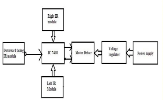
Fig .6: Obstacle avoiding Robot The block diagram of Obstacle avoidance robot is as shown in Fig. 6. The outputs of the IR sensors are given as input to 7408 IC (AND gate).The logical output from 7408 IC and its compliment acts as input to motor driver. Motor driver is powered through the supply voltage which is regulated by a voltage regulator.
ANALYSIS
The outcome of the analysis is listed in Table. The analysis is carried for two cases presence and absence of obstacle.
Case 1: Presence of Surface to Travel When there is surface for the robot to tread, the downward facing IR module outputs LOW which is inverted and then inputed to the IC 7408.
Case 1a: Absence of obstacle
When there is no obstacle the robot should move forward. During this case IR receiver receives no signal hence the output of IR module is HIGH. This signal is fed into IC 7408.
In this case HIGH output is given by the IC 7408 along with its compliment which is given to the L293D IC which makes
both the motors rotate in the clockwise direction and make the robot move forward.
Case 1b: Presence of obstacle
When there is an obstacle the robot should move away from it. During this case IR receiver receives a signal hence the output of IR module is LOW. This signal is fed into the IC 7408.
In this case LOW output is given by the IC 7408 along with its compliment which is given to the L293D IC which makes one of the motors rotate in the anti-clockwise direction and make the robot move in the other direction.
Case 2: Absence of Surface to Travel When there is no surface for the robot to tread, the downward facing IR module outputs HIGH which is inverted and then inputed to the IC 7408. This makes both the motors rotate in anticlockwise direction and stops.
Table: Movement of robot
Output of IR module
Presence of surface to travel with
obstacle Absence of surface to travel on left on right on left & right No obstacle Left Low High Low High X Right High Low Low High X middle Low Low Low Low High Motor1 (left) Moves faster Slows down Stops Moves forward Stops Motor2 (right) Slows down Moves faster Stops Moves forward Stops Robot
movement Right Left Stop Forward Stop
CONCLUSION
An obstacle avoiding robot has been designed and developed using IR sensor. Simple logic with MOSFETS is used without microcontroller to control the movement of robot in the presence of obstacle. As well the robot is designed to detect the edge of the surface so that it will not fall. The control logic of the robot movement is verified which is found to be satisfactory.
Further, Microcontroller can be used to control the movements of the wheels of the robot instead of MOSFETs. Arduino uno board with Ultrasonic sensors can be used instead of IR sensors.
REFERENCES
1. K.Vasavi and M.V.S.Praveen,“ Obstacle Detection and Avoidance Autonomous Car”, International Journal of Engineering Trends and Technology (IJETT) – Volume 9 Number 15 , 2014, pp 783-790.
2. Chokri Abdelmoula, Mohamed
Masmoudi and Fakher Chaari,
“Obstacle Avoidance of a Mobile Robot Using a Hierarchical Control”, IEEE, 3rd International Conference on Design & Technology of Integrated Systems in Nanoscale Era,2008, pp 1-5.
3. Ibrahim Alsonosi Nasir “Low Cost Obstacle Detection System for Wheeled Mobile Robot” UKACC International Conference on Control 2012,pp 529-533
4. Wen-June Wang and Jun-Wei Chang, “Implementation of a mobile robot for people Following”, International
Conference on System Science and Engineering, 2012, pp 112-116.
5. Meha Sharma, Rewa Sharma,
Gaurangi Kaushik and Swati Jha, “Design and implementation of obstacle detection algorithms in Robotics”,IEEE International Advance Computing Conference, 2014, pp 205-208.
6. Ernesto P. Lopes, Eliana P.L. Aude, Julio T.C. Silveira, Henrique Serdeira, “Obstacle Avoidance Strategy Based on Adaptive Potential Fields Generated by an Electronic Stick” International Symposium on Intelligent Signal Processing and Communications Systems, 2012, pp 2626-2631.
7. Adriana Sîrbu1 and Dan-Marius Dobrea1, “Real-Time Genetic Obstacle Avoidance Controller for a Differential
Wheeled Exploratory Robot”,
International Symposium on Signals, Circuits and Systems , 2013, pp 1 – 4. 8. T.C. Manjunath, “Novel design of a
wireless communication based
automatic surveillance system for detection of suspicious objects”, First Asian Himalayas International Conference on Internet, 2009, pp1 – 7.