Effect of grain size on the indentation hardness for polycrystalline
materials by the modified strain gradient theory
Bong-bu Jung
a, Hun-kee Lee
b, Hyun-chul Park
a,⇑ aDepartment of Mechanical Engineering, POSTECH, Pohang, Gyeongbuk 790-784, Republic of Korea
b
Department of Materials Science and Engineering, MIT, 77 Massachusetts Avenue, Cambridge, MA 02139-4307, USA
a r t i c l e
i n f o
Article history:
Received 30 January 2013
Received in revised form 24 April 2013 Available online 15 May 2013
Keywords:
Indentation test GNDs
Indentation size effect Grain boundary effect
a b s t r a c t
Numerous indentation tests in the micrometer and nanometer scale have shown that the measured hard-ness decreases significantly with increasing indentation depth, and this is known as the indentation size effect (ISE). However, several other nanoindentation results for polycrystalline materials show that the indentation hardness increases with increasing indentation depth because of the grain boundary (GB) effect. In this work, we propose a new model for the indentation test using the modified strain gradient plasticity theory. The GB effect is considered by evaluating the density of GNDs on the GB. Using the pro-posed model, the indentation hardness of polycrystalline materials in micrometer-scale structures is investigated, and compared with experimental results from other researchers.
Ó2013 Elsevier Ltd. Published by Elsevier Ltd.
1. Introduction
Indentation tests are commonly used to measure the mechani-cal properties of thin films and small volumes because of their fast, convenient and nondestructive characteristics (Oliver and Pharr, 1992). However, indentation experiments exhibit the indentation size effect (ISE) for the micrometer and nanometer scale. Numer-ous indentation tests in the micrometer and nanometer scale have shown that the measured indentation hardness increases signifi-cantly with decreasing indentation depth (Abu Al-Rub and Voyia-djis, 2004; Cao et al., 2006). The classical plasticity cannot predict the size effect because the constitutive equation of classical mechanics does not involve an intrinsic materials length scale as a parameter for the deformation.
Nix and Gao model (1998)based on the geometrically necessary dislocations (GNDs) with the Taylor dislocation model (Taylor, 1938), together with indentation results for various materials, have led to the development of the mechanism-based strain gradient (MSG) plasticity theory. In this model, the ISE model was suggested as the linear dependence of the square of the indentation hardness to the reciprocal of the indentation depth by considering the GNDs, and agrees with many experimental results. However, several other nanoindentation results show that the Nix and Gao model
cannot predict the indentation hardness with a small indentation depth, in particular because of the tip rounding, grain boundary (GB) effect and change in the storage volume for GNDs (Elmustafa and Stone, 2002; Feng and Nix, 2004; Xue et al., 2002; Yang and Vehoff, 2007)
Yang and Vehoff (2007)performed the nanoindentation test in the center of individual grains to study the effect of indentation size and grain size on the nanohardness. In this test, for larger grains the hardness always decreases with the increase in indenta-tion depth, the classical ISE. However, for smaller grains the hard-ness exhibited a behavior opposite to that of coarse grains: it increases with increase in the indentation depth, because of the GB effect. In the Nix and Gao model, the GB effect is not considered because the constitutive equation does not include the constituent grain size as a parameter for deformation.
In this paper, a model for the grain size and the ISE is proposed and compared with experimental results for polycrystalline mate-rials using the modified MSG plasticity. This model can explain both the hardening and softening effects experienced in the poly-crystalline materials by considering the GB effect.
2. Gradient plasticity theories 2.1. MSG plasticity
Taylor’s dislocation model (Taylor, 1938) gives the shear flow stress in terms of a dislocation density as:
s
¼al
b L ¼al
b ffiffiffiffiq
p ; ð1Þ0020-7683Ó2013 Elsevier Ltd. Published by Elsevier Ltd.
http://dx.doi.org/10.1016/j.ijsolstr.2013.05.002
⇑ Corresponding author. Tel.: +82 54 279 2167; fax: +82 54 279 5899.
E-mail address:[email protected](H.-c. Park).
Contents lists available atSciVerse ScienceDirect
International Journal of Solids and Structures
j o u r n a l h o m e p a g e : w w w . e l s e v i e r . c o m / l o c a t e / i j s o l s t r
Open access under CC BY-NC-ND license.
where
a
is an empirical constant usually ranging from 0.2 to 0.5,l
the shear modulus,bthe magnitude of the Burgers vector andq
the dislocation density.The dislocation density is composed of the density of the statis-tically stored dislocations (SSDs), which accumulate by trapping each other in a random way, and the density of the GNDs, which is required for the compatible deformation of various parts of the specimen.
Nix and Gao (1998) started from Taylor’s hardening law be-tween the shear strength and the dislocation density in a material:
s
¼a
l
b ffiffiffiffiffiffiq
Tp
¼
a
l
b ffiffiffiffiffiffiffiffiffiffiffiffiffiffiffiffiffiq
Sþq
G p; ð2Þ
where
q
Tis the total dislocation density, andq
Sandq
Gare the den-sities of the SSDs and GNDs, respectively. If the Taylor factor,m, is used, the uniaxial flow stress of the material can be described as:r
¼ms
¼ma
l
b ffiffiffiffiffiffiffiffiffiffiffiffiffiffiffiffiffiq
Sþq
Gp
: ð3Þ
The Taylor factormacts as an isotropic interpretation of the crystalline anisotropy at the continuum level:m¼pffiffiffi3for an iso-tropic solid andm¼3:08 for the face-centered cubic (fcc) poly-crystalline material.
In the absence of
q
G, the flow stress can be derived using the power-law hardening rule (Bishop and Hill, 1951a,b):r
¼r
refe
N¼mal
b ffiffiffiffiffiq
sp
; ð4Þ
where
r
refis the reference stress for the uniaxial tension,e
the effec-tive strain and N the work hardening exponent (06N< 1). Theeffective strain in the deformation theory of the MSG plasticity can be defined as:
e
e¼ ffiffiffiffiffiffiffiffiffiffiffiffiffi 2 3e
ije
ij r : ð5ÞThe gradient in the strain field is accommodated by the GNDs, so the effective strain gradient is described by the deformation shape:
g
¼ ffiffiffiffiffiffiffiffiffiffiffiffiffiffiffiffiffiffiffi 1 4uk;ijuk;ij r ¼ ffiffiffiffiffiffiffiffiffiffiffiffiffiffiffiffiffi 1 4g
ijkg
ijk r : ð6ÞFrom Eqs.(4)–(6), the flow stress for the MSG plasticity is ob-tained as (Nix and Gao, 1998):
r
¼r
refffiffiffiffiffiffiffiffiffiffiffiffiffiffiffiffiffi
e
2Nþlg
q; ð7Þ
wherelis the material characteristic length described as:
l¼m2
a
2l
r
ref2
b: ð8Þ
Generally, the flow theory of MSG plasticity theory is needed for complex indentation test (Qiu et al., 2003). However, in this study, deformation theory of MSG plasticity was used for simplicity be-cause the difference between deformation and flow theory of MSG plasticity is vanishingly small.
2.2. Modified strain gradient theory
The modified strain gradient theory proposed by Lee et al. (2009)is based on the assumption that the metallic polycrystalline materials are plastically nonhomogeneous. When a material de-forms, each grain in the material deforms by different amounts depending on its orientation. Thus, overlaps and voids tend to oc-cur on the GBs, and are corrected by shear displacement. This shear displacement is interpreted as local shear by the GNDs (Ashby, 1970). Therefore, two types of GNDs are considered during defor-mation in this theory: one type occurs in the slip system because of the strain gradient and the other on the GB because of
incompat-ibilities associated with potential overlaps and voids. To calculate the density of the GNDs on the GB, the following assumptions are used.
1. The grains are approximately cubic and arranged randomly. 2. The density of the GNDs on the GB is proportional to the small
strain.
For deformation of the polycrystalline materials, the two types of the GNDs are generated (Lee et al., 2009). Then the total density of the GNDs is:
q
G¼q
GSþq
GG; ð9Þwhere
q
GSandq
GGare the densities of the GNDs on the slip planes and the GB, respectively. Each density of the GNDs is related to the effective strain gradient as:q
GS¼ rg
S b ; ð10Þq
GG¼g
G b; ð11Þwhere
g
Sandg
Gare the strain gradients caused by the slip plane and the GB, respectively, andris the Nye factor, which depends on the deformation shape and the slip plane. The Nye factor is em-ployed to relate the macroscopic strain gradient to scalar measures of the GNDs density in polycrystalline materials. In general, the fac-tor has a value of 1 for single crystals and 1.85 for the bending deformation and 1.93 for the torsion deformation of FCC polycrys-talline materials (Arsenlis and Park, 1999). A value of 1.9 is assumed in this paper in order to determine the characteristic length for the polycrystalline materials in nanoindentation test.The effective strain gradient caused by the density of the GNDs on the slip plane,
g
S, is generally calculated from Eq.(6).From Eqs.(4)–(6)and Eqs.(9)–(11), we propose the flow stress relationship for the polycrystalline materials as:
r
MSG¼r
ref ffiffiffiffiffiffiffiffiffiffiffiffiffiffiffiffiffiffiffiffiffiffiffiffiffiffiffiffiffiffiffiffiffiffie
2Nþlðg
Sþg
GÞ q : ð12ÞThen, the corresponding indentation hardness can be obtained by choosing the Tabor’s factor of 3:
HMSG¼3rMSG¼3rref
e
NP ffiffiffiffiffiffiffiffiffiffiffiffiffiffiffiffiffiffiffiffiffiffiffiffiffiffiffiffiffiffiffiffiffiffiffiffiffiffiffi 1þlðg
Sþg
GÞ=e
2PN q ¼HA ffiffiffiffiffiffiffiffiffiffiffiffiffiffiffiffiffiffiffiffiffiffiffiffiffiffiffiffiffiffiffiffiffiffiffiffiffiffiffiffiffiffiffiffiffiffiffiffiffiffiffiffiffiffiffiffiffiffiffiffiffiffiffiffiffiffiffiffi 1þ 9 H2A ! ðm2a
2l
2bÞðg
Sþg
GÞ v u u t ; ð13Þwhere the classical indentation hardness value,HA, is given by:
HA¼3rref
e
NP: ð14Þ3. Indentation model for polycrystalline materials
For the nanoindentation model, the indenter tip was assumed as a rigid circular cone.Fig. 1shows the simplified axisymmetric indentation model, whereais the radius of the contact area and hthe indentation depth. The angle between the tip and the surface of the specimen wash. In this study, the indenter tip angle was converted to 19.68°, which is equivalent to the Berkovich tip. The relationships betweena,handhare given as:
A¼24:56h2¼
p
a2; tanh¼h=a: ð15Þ
Nix and Gao developed the equation for the ISE in single crys-tals by considering the density of the GNDs around a conical in-denter. In this model, to calculate the density of the GNDs they assumed that the indentation is accommodated by circular loops
of the GNDs with the Burgers vectors normal to the surface plane. As the indenter penetrates into the surface, the GNDs on the slip system are required to account for the permanent shape change at the surface. Then, the total length of injected dislocation loops to form the shape of conical indenter is given as:
k¼
p
hab ¼
p
a2tanhb ; ð16Þ
wherebis the Burgers vector.
It is assumed that the evolution of GNDs during the indenta-tion is primarily governed by a large hemispherical volume with the radius of contact areaa. However, the GNDs will spread yond the hemispherical, because of the strong repulsive force be-tween GNDs for very small indentation depth. To modify the plastic zone radius, Durst et al. (2006)proposed that the radius of the plastic zone is assumed to be fa, where fP1 can be interpreted as the ratio of the radii of the plastic zone and the contact. It is assumed that all injected GNDs loops remain within a hemisphere with radiusc. Then, the volume of the plastic zone is: VP¼ 2 3
p
c 3¼2 3p
f 3a3: ð17ÞTherefore, the density of the GNDs on the slip systems is deter-mined as:
q
GS¼ k Vp ¼ 3 2f3bhtan 2 h: ð18ÞFrom Eqs.(10) and (18), the strain gradient caused by the slip plane is given as:
g
S¼ 3 2f3h 1 rtan 2 h: ð19ÞFor a conical indenter, it is assumed that the displacement is proportional to the indentation depthhand the strain field should depend only on the normalized indentation depth,h/abased on the assumption of a self-similar deformation field (Biwa and Storakers, 1995; Storakers et al., 1997). Then, the average plastic strain is gi-ven by:
e
P¼kðh=aÞ ¼ktanh; ð20Þwherekis the constant usually ranging from 0.2 to 0.4. A value of 0.2 is assumed in this paper. The average strain is independent of the indentation depth.
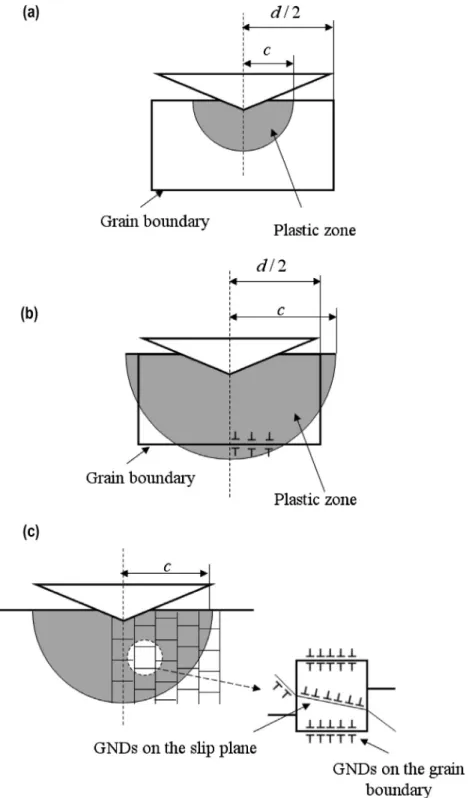
It is assumed that the GNDs on the GB are considered in the plastic region only to calculate the density of the GNDs on GB. The radius of the plastic zone varies directly with the indentation depth. Therefore, the density of the GNDs on the GB changes with
the range of indentation depth as shown inFig. 2. For a radius of plastic zone, c, is smaller than half of the grain size, d/2, as the GB is not included within the plastic zone as shown inFig. 2(a), the GNDs is not generated on the interface. Then, density of the GNDs on the GB is defined as:
q
GG¼0: ð21ÞFor this case, one can assume that there is no GB effect, and be-cause the grain can be treated as single crystal in this range, the Nye factor, r, and Taylor factor, m, have values for single crystals:
r¼1; m¼pffiffiffi3: ð22Þ
From Eqs.(13), (19), (21), and (22), the indentation hardness can be obtained by:
HMSG¼HA ffiffiffiffiffiffiffiffiffiffiffiffiffiffiffiffiffiffiffiffiffiffiffiffiffiffiffiffiffiffiffiffiffiffiffiffiffiffiffiffiffiffiffiffiffiffiffiffiffiffiffiffiffiffiffiffiffiffiffiffiffiffiffiffiffiffiffiffi 1þ 27 H2 A ! 3a 2
l
2btan2h 2f3 1 h v u u t : ð23ÞFord=26c<pffiffiffi2d=2, parts of the GB are contained within the plastic zone, as seen in Fig. 2(b) and increase with increasing indentation depth. Assuming that the normal strain in the direc-tion of indentadirec-tion is the dominant component, we consider that the GNDs are generated on the GB, which is perpendicular to the indentation direction. Because the number of the GNDs on the polycrystalline GB is given as
e
Pd=4bbased on theAshby relation-ship (1970), the total length of the GNDs on the GB betweenrand r + drcan be calculated as:dlG¼2pr
e
p4bdr: ð24Þ
Integration of Eq. (24) from 0 to
ffiffiffiffiffiffiffiffiffiffiffiffiffiffiffiffiffiffiffiffiffi
c2d2=4 q
yields the total length using the probability of the GBs in the plastic zone, N0¼ c d=2, as: lG¼2 Z ffiffiffiffiffiffiffiffiffiffiffiffiffic2d2= 4 p 0 2pr
e
p 4bdr c d=2 ¼pe
p b c3 d cd 4 ; ð25ÞThe density of the GNDs can be obtained as:
q
GG¼ lG VP ¼ 3ep bf3a3 c3 d cd 4 : ð26ÞAs the Nye factor,r, and Taylor factor,m, have values for the polycrystalline material, the indentation hardness can be obtained from Eqs.(13), (19), and (26):
HMSG¼HA ffiffiffiffiffiffiffiffiffiffiffiffiffiffiffiffiffiffiffiffiffiffiffiffiffiffiffiffiffiffiffiffiffiffiffiffiffiffiffiffiffiffiffiffiffiffiffiffiffiffiffiffiffiffiffiffiffiffiffiffiffiffiffiffiffiffiffiffiffiffiffiffiffiffiffiffiffiffiffiffiffiffiffiffiffiffiffiffiffiffiffiffiffiffiffiffiffiffiffiffiffiffiffiffiffiffiffiffiffiffiffiffiffiffiffiffi 1þ 81 2
a
2l
2b H2 A ! 3 3:8f3htan 2hþ 3ep bf3a3 c3 d cd 4 ! v u u t : ð27ÞAs seen in Eq.(27), the indentation hardness increases with the increase in the indentation depth because of the GB effect in this depth range.
ForcPpffiffiffi2d=2 as shown inFig. 2(c), the GB probability in the plastic zone isN0¼1þðcd=2Þ
d . Therefore, using the procedure pro-posed byLee et al. (2009), the length and density of the GNDs on the GBs are given by:
lG¼2 Z c 0 2pr
e
p 4bdr ðN 0 Þp
4¼p
2e
p 8 c2 bN 0 ; ð28Þq
GG¼ lG VP¼ 3pep 16bf3a3N 0: ð29ÞThe indentation hardness can be obtained from Eqs.(13), (19), and (29): HMSG¼HA ffiffiffiffiffiffiffiffiffiffiffiffiffiffiffiffiffiffiffiffiffiffiffiffiffiffiffiffiffiffiffiffiffiffiffiffiffiffiffiffiffiffiffiffiffiffiffiffiffiffiffiffiffiffiffiffiffiffiffiffiffiffiffiffiffiffiffiffiffiffiffiffiffiffiffiffiffiffiffiffiffiffiffiffiffiffiffiffiffiffiffiffiffiffiffiffiffiffiffiffiffiffiffiffiffi 1þ 81 2
a
2l
2b H2A ! 3 3:8f3htan 2 hþ 3pep 16bf3a3N 0 ! v u u t : ð30ÞAs seen in Eqs.(23), (27), and (30), the proposed model consid-ers the GNDs on both the slip plane and Gb.
4. Results and discussion
Fig. 3compares the hardness predictions by the proposed mod-el with the experiment result of Yang for the Ni plate specimen (Yang and Vehoff, 2007). In this test, the dependence of the hard-ness on indentation size and on grain size was studied by perform-ing a nanoindentation test at the center of the individual grains and by varying the grain size and indentation depth. As seen in
Fig. 3, the hardness decreases monotonically with increasing indentation depth for a grain size of 80
lm which is considered a
Fig. 2.The occurrence of GNDs on the grain boundary according to relation between the radius of plastic zone and the grain size. (a) Forc<d=2, (b) Ford=26c<pffiffiffi2d=2, (c) Forc>pffiffiffi2d=2.large grain. However, for smaller grain sizes, hardness increases with increasing indentation depth at a specific range. Nix and Gao model cannot predict this result because it does not consider the GB effect. Generally, for small indentation depth as shown in
Fig. 2(a), the flow stress is governed by the continued nucleation and activation of new sources because the grain is considered as single crystals in this case. Then the flow stress in this range is
soft-ened by the presence of dislocations as in the case of the Nix and Gao model. Plasticity is initiated by dislocation nucleation at theo-retical shear stress. As plastic deformed volume is contacted with GBs as shown in Fig. 2(b), the hardening is preceded due to the GB. The GBs are regarded as obstacles to dislocation motion or a source of dislocations. Therefore the dislocation pileup or disloca-tion forest is generated in regions close to the GBs. Then higher stress is required to move dislocations through these pileup or for-est. This effect caused by the GB is considered by calculating the density of the GNDs on the GB in this model. The proposed model agrees with experiments, as shown inFig. 3.
In calculating the hardness, the material parameters were determined by curve fitting and the results are shown inTable 1. The relationship betweenHAand the grain size inTable 1follows the Hall–Petch relation (Hall, 1951; Petch, 1953). Generally, for indentation test, value of the empirical constant
a
= 0.5 is chosen due to the complex stress field dislocation substructures (Durst et al., 2007). Therefore, fitted empirical constanta
has from 0.43 to 0.48 in our study, which is reasonable. The average calculated shear modulus is about 81.67 GPa, which agrees well with that inMeyers and Chawla (1999), and the range of the parameter fis from 3.2 to 4.3, which agrees well with the reference value. ( Ty-miak et al., 2001)
To estimate the size effect using the proposed model, the inden-tation hardness in Eq.(30)was normalized by the classical inden-tation hardness,HA. The normalized indentation hardness is then given as: HMSG HA ¼ ffiffiffiffiffiffiffiffiffiffiffiffiffiffiffiffiffiffiffiffiffiffiffiffiffiffiffiffiffiffiffiffiffiffiffiffiffiffiffiffiffiffiffiffiffiffiffiffiffiffiffiffiffiffiffiffiffiffiffiffiffi 1þl0 A dþ A 2fþ 3 tanh 4f3 1 h s for cPpffiffiffi2d=2 )l0¼81a 2
l
2b H2 A ; A¼3pep 16 : ð31ÞAs shown in Eq.(31), the normalized hardness is related to the grain size and the indentation depth. This relation shows a linear relationship betweenHMSGand 1=h, which corresponds to the Nix and Gao model, and agrees with the indentation data for the poly-crystalline material with fine grains byCao et al. (2006). This rela-tion also predicts that the specimen with smaller grains has higher hardness at the same indentation depth, which agrees with the Hall–Petch relation.
5. Conclusions
We have investigated the indentation hardness for polycrystal-line materials in micrometer and nanometer scale structures. The following conclusions are drawn.
1. We propose a new model for predicting indentation hardness of the polycrystalline materials using the modified MSG theory. The density of the GNDs is calculated based on the nonhomoge-neity of the polycrystalline materials and the slip plane. 2. The total density of the GNDs changes with indentation depth.
For small indentation depth (c<d=2), the grain can be consid-ered as single crystals because the GNDs is not generated on the GBs. However, for middle depth range (d=26c<pffiffiffi2d=2), the
GB effect is considered by the density of the GNDs on GBs, Fig. 3.Comparison of the experimental data and the predicted indentation
hardness by proposed bending model for (a) 0.85lm grain size, (b) 1.35lm grain size, and (c) 80lm grain size.
Table 1
Mechanical parameters derived by fitting of experimental data (by Yang and Vehoff).
d(lm) a HA(GPa) l(GPa) f
80 0.48 2.15 83 3.2
1.35 0.44 3.52 83 4.3
which act as obstacles to dislocation movement. Then, the hard-ness increases with the increase in indentation depth in this range. For a larger depth (c>pffiffiffi2d=2), the GNDs density decreases with increasing indentation depth and increases with the decrease in the grain size. The predicted hardness by the proposed model agrees fairly well with the experimental results conducted byYang and Vehoff (2007).
3. We have demonstrated that the proposed model can explain the indentation hardness in polycrystalline materials. The pro-posed model shows that the grain size is an important factor in estimating the ISE for the polycrystalline materials in the micrometer and nanometer scale.
References
Abu Al-Rub, R.K., Voyiadjis, G.Z., 2004. Analytical and experimental determination of the material intrinsic length scale of strain gradient plasticity theory from micro- and nano-indentation experiments. Int. J. Plast. 20, 1139–1182.
Arsenlis, A., Park, D.M., 1999. Crystallographic aspects of geometrically necessary and statistically stored dislocation density. Acta Mater. 47, 1597–1611.
Ashby, M.F., 1970. The deformation of plastically non-homogeneous mateials. Philos. Mag. 21, 399–424.
Bishop, J.F.W., Hill, R., 1951a. A theory of the plastic distortion of a polycrystalline aggregate under combined stresses. Philos. Mag. 42, 414–427.
Bishop, J.F.W., Hill, R., 1951b. A theoretical derivation of the plastic properties of a polycrystalline face-centered metal. Philos. Mag. 42, 1298–1307.
Biwa, S., Storakers, B., 1995. An analysis of fully plastic brinell indentation. J. Mech. Phys. Solids 43, 301–330.
Cao, Y., Allameh, S., Nankivil, D., Sethiaraj, S., Otiti, T., Soboyejo, W., 2006. Naonindentation measurements of the mechanical properties of polycrystalline Au and Ag thin films on silicon substrates: effects of grain size and film thickness. Mater. Sci. Eng. A 427, 232–240.
Durst, K., Backes, B., Franke, O., Göken, M., 2006. Indentation size effect in metallic materials: modeling strength from pop-in to macroscopic hardness using geometrically necessary dislocations. Acta Mater. 54, 1668–1686.
Durst, K., Franke, O., Böhner, A., Göken, M., 2007. Indentation size effect in Ni–Fe solid solutions. Acta Mater. 55, 6825–6833.
Elmustafa, A.A., Stone, D.S., 2002. Indentation size effect in polycrystalline FCC metals. Acta Mater. 50, 3641–3650.
Feng, G., Nix, W.D., 2004. Indentation size effect in MgO. Scr. Mater. 51, 599–603.
Hall, E.O., 1951. The deformation and aging of mild steel: III. Discussion of results. Proc. Phys. Soc. London B64, 747–753.
Lee, H., Bong, B., Kim, Y., Hwang, W., Park, H., 2009. Analysis of flow stress and size effect on polycrystalline metallic materials in tension. Mater. Sci. Eng. A 527, 339–343.
Meyers, M.A., Chawla, K.K., 1999. Mechanical Behaviors of Materials. Prentis-Hall, p. 92.
Nix, W.D., Gao, H., 1998. Indentation size effect in crystalline materials: a law for strain gradient plasticity. J. Mech. Phys. Solids 46, 411–425.
Oliver, W.C., Pharr, G.M., 1992. An improved technique for determining hardness and elastic modulus using load and displacement sensing indentation experiments. J. Mater. Res. 7, 1564–1583.
Petch, N.J., 1953. The cleavage strength of polycrystals. J. Iron Steel Inst. 174, 25–28.
Qiu, X., Huang, Y., Wei, Y., Gao, H., Hwang, K.C., 2003. The flow theory of mechanism-based strain gradient plasticity. Mech. Mater. 35, 245–258.
Storakers, B., Biwa, S., Larsson, P.L., 1997. Similarity analysis of inelastic contact. Int. J. Solids Struct. 34, 3061–3083.
Taylor, G.I., 1938. Plastic strain in metals. J. Inst. Met. 62, 307–324.
Tymiak, N.I., Kramer, D.E., Bahr, D.F., Wyrobek, T.J., Gerberich, W.W., 2001. Plastic strain and strain gradients at very small indentation depths. Acta Mater. 49, 1021–1034.
Xue, Z., Huang, Y., Hwang, K.C., Li, M., 2002. The influence of indenter tip radius on the micro-indentation hardness. J. Eng. Mater. Technol. Trans. ASME 124, 371– 379.
Yang, B., Vehoff, H., 2007. Dependence of nanohardness upon indentation size and grain size – a local examination of the interaction between dislocations and grain boundaries. Acta Mater. 55, 849–856.