Design and Construction of Passively
Articulated Ornithopter Wings
Alexander Timothy Mastro
A thesis submitted to the faculty of the University of North Carolina at Chapel Hill in partial fulfillment of the requirements for the degree of Master of Science in the Department of Biomedical Engineering
Chapel Hill 2012
c
2012
Alexander Timothy Mastro All Rights Reserved
Abstract
Alexander Timothy Mastro : Design and Construction of Passively Articulated Ornithopter Wings
(Under the direction of Robert Dennis, PhD)
Birds, bats, and insects are able to fly efficiently and execute impressive in-flight,
landing, and takeoff maneuvers with apparent ease through actuation of their highly
articulated wings. This contrasts the approach used to enable the flight of
compar-atively simple man-made rotary and fixed wing aircraft. The complex aerodynamics
underlying flapping-based flight pose an everpresent challenge to scienctists hoping
to reveal the secrets of animal flight. Despite this, interest in engineering aircraft
on the bird and insect scale is higher than ever. Herein, I present my attempt to
design and construct bioinspired passively articulated ornithopter wings. Two
differ-ent hinge-based joint design concepts are investigated across several design iterations.
The advantages and disadvantages of each implentation are discussed. Finally, the
necessary instrumentation to analyze the performance of the wings is designed and
fabricated, followed by testing of the wings.
Acknowledgements
I would like to thank Ty for sponsoring my research assistantship and giving me
the opportunity to work on so many cool projects in his lab. I have become a better
engineer through my time there. Thank you, Rungun, for your collaboration. Thanks,
Bob, for your invaluable advice. Steve, thanks for teaching me how to make things.
To my parents.
Table of Contents
List of Tables . . . viii
List of Figures . . . ix
List of Abbreviations and Symbols . . . x
1 Introduction 1 1.1 Motivation . . . 1
1.2 Background . . . 2
1.3 Thesis Overview . . . 3
2 System Design 4 2.1 Specifications and Requirements . . . 4
2.2 Preliminary Simulation . . . 5
2.3 Design Implementation and Iterations . . . 6
2.3.1 Flapping Platform . . . 6
2.3.2 The Hinge . . . 7
2.3.3 Structural Members . . . 10
2.3.4 Wing Membrane . . . 12
2.4 Measuring Apparatus . . . 13
2.4.1 Cantilevered Beam . . . 14
2.4.2 Morehouse Proving Ring . . . 15
2.4.3 Measurement Results . . . 18
3 Discussion 21
3.1 Further Testing . . . 21
3.2 Wing Design Improvements . . . 22
3.3 Conclusion . . . 23
Bibliography 25
List of Tables
2.1 Results of the load cell frequency study in SolidWorks . . . 16
2.2 Spring constants used for testing . . . 19
2.3 Wingbeat frequency (Hz) vs driving voltage (Vdrive) . . . 19
2.4 Average lift (mN) vs driving voltage (Vdrive) . . . 20
List of Figures
2.1 Assembly for simulating flapping of a passive joint in SolidWorks . . . 6
2.2 Mk1 hinge . . . 8
2.3 Mk1 hinge front view . . . 8
2.4 Mk2 hinge . . . 9
2.5 Mk2 hinge shim detail . . . 9
2.6 Mk3 hinge flexed . . . 9
2.7 Mk3 hinge straight . . . 9
2.8 Graphite rods bonded with a cross joint . . . 10
2.9 Graphite rods bonded with a butted joint . . . 10
2.10 Wing structure layout . . . 11
2.11 Rigid wing structure and membrane prior to assembly . . . 13
2.12 Wheatstone bridge . . . 14
2.13 Load cell strain simulation in SolidWorks . . . 16
2.14 Load cell frequency study in SolidWorks . . . 17
2.15 Load cell gage locations . . . 17
2.16 Data acquisition flowchart . . . 19
List of Abbreviations and Symbols
µS microstrain (= strain×10−6)
CA cyanoacrylate
DC direct current
Hz Hertz
mN milliNewton
USB Universal Serial Bus
Chapter 1
Introduction
1.1
Motivation
The aerodynamics of flapping flight are complex and poorly understood in
com-parison to those of the fixed and rotary wing aircraft in common use today. The
mechanisms that fixed wing aircraft and birds use to control flight are
fundamen-tally different. Instead of adjusting thrust output and the orientation of discrete
flight control surfaces, birds modify the flapping kinematics of their wings to control
velocity, position and attitude. Using their wings, birds are able to effortlessly
exe-cute complex in-flight, landing, and takeoff maneuvers that would be challenging for
human-engineered, fixed-wing aircraft to replicate.
Recently, there has been resurgence of interest in building small-scale aircraft
capable of achieving the efficient, agile flight exhibited by flying birds, bats and
insects. As engineers attempt to design air vehicles on this scale, it makes sense
to look to nature for inspiration. Bioinspired design leverages the results of the
entirety of evolutionary history to better engineer concepts that nature has already
optimized. By building wings that achieve greater similarity to the highly articulated
wings present in biology and analyzing their performance, we may gain a better
understanding of how to implement these wings in a flying machine that is one step
1.2
Background
Flying birds exist in sizes ranging across orders of magnitude in weight and wingspan,
yet retain similar musculoskeletal structures. Flying locomotion, by animal or
ma-chine, is efficient in terms of energy expenditure per distance traveled, but is costly
per unit time [1], [2]. Birds have evolved to mitigate this cost by moving the control
structures necessary for flight as close to the pivot as possible to minimize the moment
of inertia [3].
Past research has shown that underactuation of bird wings can yield flight.
Headley (1895) demonstrated over 100 years ago that just the shoulder provides the
musculature necessary to extend and flex the wing. By extending the shoulder of a
dead bird, he observed automatic extension of the wrist joint and spreading of the
feathers [4]. Fisher (1957), later discovered that pigeons were still capable of flight
even after severing the tendons responsible for wrist extension and flexion [5].
Current engineering approaches, such as the Festo SmartBird [6] and other U.S.
patents [7], [8], attempt to fully actuate the wrist joint with stiff mechanical linkages
instead of allowing compliant flexing under aerodynamic and inertial loading. One of
the problems with this approach is that energy is wasted coercing the joint to do what
it otherwise might accomplish naturally. This contrasts the underactuated approach
that birds use to fly [5]. Another advantage of underactuation is that control tasks
are shifted from the electronic or neural control circuitry to the intrinsic mechanical
structures of the wing [9]. These factors make underactuation attractive from both an
energetic cost and control complexity standpoint and suggest that bioinspired design
using principles of underactuation is appropriate for constructing biologically-similar
bird wings.
1.3
Thesis Overview
I present my attempt to design, construct, and test ornithopter wings that are able to
flex about a joint passively, without additional actuation. Chapter 2 covers the design
and construction of the wings and measurement apparatus. Section 2.4.3 provides a
brief overview of the testing procedures and results. Further testing, potential design
improvements, and concluding remarks are detailed in Chapter 3.
Chapter 2
System Design
2.1
Specifications and Requirements
The most successful flapping wings are those built by nature. One of the most
no-ticeable aspects of wing movement during bird flight, especially during takeoff, is the
high degree of wing flexion that occurs during upstroke. Wing flexion occurs at the
wrist to minimize air resistance during upward movement [10], [11]. In an attempt to
bring the performance of engineered wings closer to that of bird wings, the following
requirements were proposed for the ornithopter wing design:
• Lightweight with mass distributed as close to the proximal end of the wing as
possible.
• Adaptable to an existing flapping platform.
• Wingspan comparable to ringed turtle-dove (Streptopelia risoria).
• 2D profile roughly similar to that of Streptopelia risoria.
• The wing should have a single, flexing, passive degree of freedom.
• Joint requirements:
– Located analogously toStreptopelia risoria’s wrist.
– Able to withstand high-impact, cyclical loading.
– Integrated spring element to restore wing to extension at the end of
up-stroke.
– Lightweight.
2.2
Preliminary Simulation
Before embarking on construction of the wings, we wanted validation of whether a
wing actuated only at the base with a single passive joint could produce qualitatively
“good” flapping. A rough model of flapping behavior was simulated in SolidWorks
using a Motion Study. Simulation parameters were estimated, then adjusted based
on the simulation output. The simulation included the following:
• gravity
• mass and inertia of the assembly parts
• a rotary spring constant at the joint to simulate the spring element contained
within the hinge
• a rotary damping constant at the joint to simulate the effect of air resistance
on the distal portion of the wing
• the driving frequency of the motors
• crankshaft-like translation of rotary to reciprocating motion.
We decided that full extension at the top of upstroke and flexion greater than
40◦ at the end of downstroke would be indicative of good flapping performance. We were able to successfully simulate this behavior via slight variation in the driving
frequency and changes to the damping and spring constants. The simulation
sug-gested that there was a relationship between the wingbeat frequency and the spring
Figure 2.1: Assembly for simulating flapping of a passive joint in SolidWorks
constant required to return the distal portion of the wing to full extension at the
end of upstroke. For a given wing, higher flapping frequencies necessitated larger
spring constants to return the distal portion of the wing to extension at the end of
upstroke. If the wingbeat frequency was excessively high, or the spring constant too
low, the wing would remain bent at the top of upstroke. These results made
intu-itive sense because higher flapping frequencies necessitated larger joint moments to
produce greater angular accelerations to extend the wing.
2.3
Design Implementation and Iterations
2.3.1
Flapping Platform
The flapping platform used to conduct the lift experiments implemented driving
hard-ware from the commercial Cybird ornithopter [12]. The ornithopter driving hardhard-ware
was mounted to a rigid rod, which was in turn mounted to a custom load cell.
Be-hind the driver assembly, a Delrin plate allowed the integration of a 200
pulse-per-revolution rotary encoder with the flapping drivetrain for closed-loop control of the
wingbeat frequency via a Polulu Jrk 21v3 Universal Serial Bus (USB) motor controller
with feedback.
2.3.2
The Hinge
The design and implementation of the hinge was perhaps one of the most important
determinants of the performance of the passively articulated wings. To be able to
fly successfully, the hinge needed to satisfy several requirements located on opposing
ends of the engineering spectrum. Impact resistance over thousands of loading cycles,
low rotational resistance, adaptable to the rest of the wing frame, and low weight.
Shim-based Flexure Hinge
The shim-based hinge was initially attractive for a variety of reasons. Because the
design was free of sliding parts typical of captured-pin hinges, the flexure hinge could
allow rotation of the distal portion of the wing about the joint with zero frictional
losses. The shim material used to implement the flexure hinge was 0.002 in thick 1095
blue tempered spring steel shim stock from Lyon Industries. Due to its high yield
strength, the spring steel shim was able to deform considerably before entering the
plastic deformation region. Because the essential component of the hinge, the shim,
weighed 0.44 g, a very lightweight hinge could have been constructed that satisfied
the low rotational resistance, low weight and integrated spring requirements.
The first implementation of the flexure hinge, the Mk1 hinge, depicted in
fig-ures 2.2 and 2.3, was constructed using a simple clamp design with a stop bolted
to the front section of the top half of the hinge. The clamping action of the hinge
mechanically secured the joint by compressing the shim and the mounting sections of
the wing structure between the clamp halves. During initial testing of Mk1 hinge, we
found that the mounting location of the stop resulted in asymmetrical forces acting
about the hinge as extension of the distal portion of the wing at the top of upstroke
brought the hinge to its fully extended position. At the top of upstroke, the contact
force of the stop was localized to the front half of the hinge, causing torsion of the
distal portion of the wing about an axis roughly parallel to the main spar axis.
Ad-ditionally, because the stop of the Mk1 hinge was not constrained from moving in
the extended position, the flexibility of the shim allowed the hinge to buckle, causing
hyperextension of the joint at the end of upstroke. Besides allowing inappropriate
degrees of freedom in the wing, torsion and hyperextension of the joint lead to rapid
wear and cracking of the shim steel flexure element.
Figure 2.2: Mk1 hinge. The shim ma-terial is colored purple for clarity.
Figure 2.3: Mk1 hinge front view
The Mk2 hinge, shown in figures 2.4 and 2.5, was designed with an integrated stop
along its entire length to solve the problem of torsion at the top of upstroke. The
integrated stop eliminated the torsional and hyperextension issues of the Mk1, but
the additional material required to implement the feature compounded the extant
problem of weight in the shim-based flexure hinge. Although both produced passable
flapping performance, the weight of the shim-based hinges proved to be too excessive
for continued use without a redesign of the rest of the wing structure to allow better
integration of the shim steel stock.
Figure 2.4: Mk2 hinge Figure 2.5: Mk2 hinge shim detail
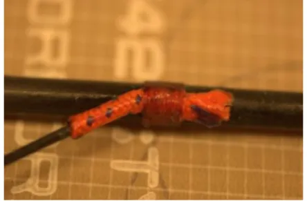
Barrel Hinge
To address the problem of weight in the Mk1 and Mk2 hinges, the Mk3 hinge was
de-veloped using a more traditional captured-pin hinge design. The Mk3 hinge, shown in
figures 2.6 and 2.7, was implemented using off-the-shelf barrel hinges from WoodRiver
that were bored to fit the graphite rods used to construct the wing structure. Each
wing included a pair of barrel hinges with stops to prevent torsion at the top of
up-stroke. The stops were made from sections of brass tubing soldered to the distal end
of the joint. Because the barrel hinges lacked integrated springs, mounting hooks to
attach external springs were bonded to the stops using cyanoacrylate (CA) soaked
nylon thread. Steel music wire extension springs from McMaster Carr ranging in
stiffness from 0.57 to 3.03 lbs/in were tested later on to determine the relationship
between joint spring constants and flapping performance.
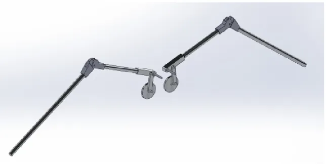
Figure 2.6: Mk3 hinge flexed Figure 2.7: Mk3 hinge straight
2.3.3
Structural Members
The structural members for the wings were made from 3.2 mm and 1.6 mm diameter
graphite rods bonded together using a combination of nylon thread, fishing line,
hollow-cored utility cord, and CA glue. There were two types of joints in the wing:
butt and cross joints. Each type of joint was constructed with its own bonding
technique. The cross joints were secured with CA-soaked thread that was wrapped
around the cross both ways. An example cross joint is shown in figure 2.8. To
construct the butted joints, a short section of 1/8 in hollow cored utility cord was
slipped over the end of the member to be butted against a straight section. This
hollow cord was temporarily secured to the butted member with a small amount of
CA glue. The free section of cord extending past the graphite rod was lashed to
the straight member using 15 lb polyvinyl fishing line, yielding a result similar to
the butted joint in figure 2.9. After the lashing was secured with knots, the entire
joint was soaked in CA glue and hardened with INSTA-SET CA accelerant from Bob
Smith Industries. The CA accelerant enabled faster assembly of the wing structure by
shortening curing times, which allowed the structure to be handled without disrupting
the CA polymerization. The spars were bonded together according to the layout
depicted in figure 2.10. The bonding technique for assembling the joints was derived
from ornithopter construction methods developed by K. Kakuta [13].
Figure 2.8: Graphite rods bonded with a cross joint
Figure 2.9: Graphite rods bonded with a butted joint
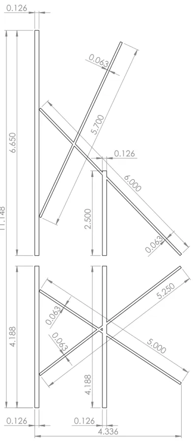
Figure 2.10: Wing structure layout. The layout was used as a template during bonding of the graphite rods. The top half of the figure shows the structure of the distal portion of the wing, while the proximal portion is depicted on the bottom. Units are in inches.
4.188
6.650
2.500
6.000
5.700
4.188
5.250
5.000 0.063
0.063
0.126 0.126
0.126
0.063
0.063
0.126
11.148
4.336
2.3.4
Wing Membrane
The wing membrane was assembled from two components: Orcon AN-36W film, and
3M 9460PC VHB adhesive transfer tape. The Orcon film is a metalized polyvinyl
flu-oride film reinforced on one side with nylon yarns intended to be used as a lightweight
insulation covering film. The lightweight, reinforced nature of the film made it a good
candidate for wing membrane material. The 3M adhesive transfer tape allowed
ap-plication of strips of a pressure-sensitive adhesive to the Orcon film. The process for
assembling the wing membrane was as follows:
1. Laser cut the outline of the wing allowing enough extra material to fold over
the main spar.
2. Cut out sections of 0.5 in width in lengths proportional to the non-main spar
members. Make these sections slightly longer than the member length.
3. After cutting the membrane, bond the transfer tape to the section of the wing
to be folded over the main spar.
4. Bond the transfer tape to the backing membrane material
5. Fold the extra material at the top of the wing outline over the main spar.
6. Secure the rest of the membrane material to the wing by sandwiching the
graphite rods in between the wing outline material and the backing material.
7. Reinforce the edges of the wing and the edges of any holes in the wing with
additional layers of Orcon film and adhesive transfer tape.
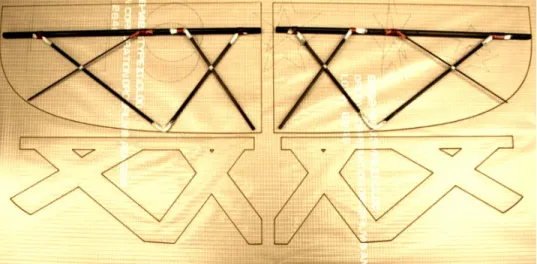
Figure 2.11 shows a rigid wing prototype resting on the laser cut film prior to assembly.
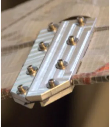
Figure 2.11: Rigid wing structure and membrane prior to assembly. The graphite wing structure is resting on the top half of the wing membrane. The structure will be sandwiched between the top and bottom membrane cutouts. The Orcon AN-36W membrane was laser cut, then bonded to the wing structure using 3M 9460PC adhesive transfer tape.
2.4
Measuring Apparatus
To measure net lift generated by the flapping assembly, it was necessary to use a
transducer to convert the forces produced to a voltage that could be recorded using a
data logging scheme. One of the most widely used force transduction techniques is to
measure the strain that a deformable object experiences under load using strain gages.
Strain gages are made from a network of foil wires epoxied to a polyimide or Kapton
film. The film is then bonded to the material at the desired strain measurement
point. It is important to ensure that the strain gage experiences the same strain
as the material to be able to produce an accurate measurement. A low viscosity
CA adhesive is commonly used when the measurements occur in a relatively clean
environment. To convert the changes in resistance of the strain gages into measurable
voltages, a circuit arrangement called the Wheatstone bridge, shown in figure 2.12,
can be used. A direct current (DC) voltage, VAC, is applied across the bridge to
produce the output,VG, which is dependent on the resistances of the bridge elements.
VG is calculated below:
IR1R2 =
VAC
R1+R2
IR3R4 =
VAC
R3+R4
VD =IR1R2R2 VB =IR3R4R4
VD =
R2
R1+R2
VAC VB =
R4
R3+R4
VAC
VG=VD −VB VG =
R2
R1+R2
− R4
R3+R4 VAC R1 R4 R2 VG R3 A B D C
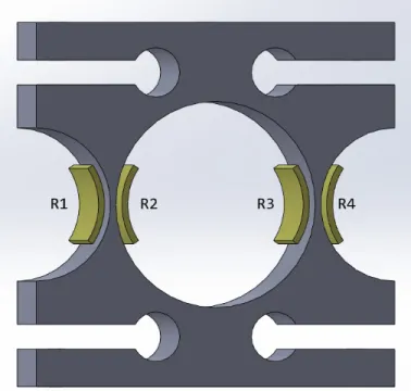
Figure 2.12: Wheatstone bridge [14]. A DC potential is applied across A and C to yield the output,VG. In a half-bridge configuration,R1 andR2 are strain gages, while
R3 and R4 are used to balance the bridge. In a full-bridge configuration, R1, R2, R3, and R4 are strain gages and offset nulling is required. In both cases, the strain gages are arranged to experience opposing strains when the substrate is deformed.
2.4.1
Cantilevered Beam
The initial force measurements were conducted using KFG-3-120-C1-11L1M2R strain
gages from Omega mounted in a half-bridge configuration to a cantilevered beam
made from 6061-T6 aluminum. The gages were bonded with SG401 ethyl-based CA
from Omega. To avoid corruption of the force measurements due to resonance of the
cantilevered structure, the beam length were shortened to increase the structure’s
base resonant frequency. Three cantilevered beam lengths were tested, all of whose
resonant frequencies (12 Hertz (Hz), 24 Hz, 50 Hz) were higher than the tested
flap-ping frequencies (2 Hz – 8 Hz). Interestingly, as the cantilever structure became
stiffer, the portion of the signal in the Fourier transform corresponding to the
reso-nant frequency increased, contrary to expectations. One possible explanation for this
phenomena was that the abrupt contact forces produced at the hinge stop resulted in
impulse-like stimulation of cantilever, leading to repeated excitation of the structure’s
resonant frequencies.
2.4.2
Morehouse Proving Ring
Morehouse Proving Rings have typically been used as instruments for the static
cal-ibration of other load sensors. Traditional operation of the ring involves moving a
micrometer-controlled surface up toward a vibrating reed until damping of the reed’s
movement is observed. To enable dynamic load measurements, a faster transducer is
required. The ring is well-suited for use with strain gages since placement of gages
on the sides of the ring in a full-bridge configuration results in the cancellation of
uneven axial strain effects from the bridge output. A modified ring design was
cho-sen to facilitate mounting of the flapping assembly [15]. The ring was machined from
6061-T6 aluminum. The critical design dimensions were modified to achieve sufficient
levels of surface strain based on loading simulations conducted in SolidWorks (see
fig-ure 2.13). Table 2.1 shows the load cell’s top five resonant modes calculated using
a SolidWorks frequency simulation. The dominant resonant mode at 540 Hz, shown
in figure 2.14, suggested that the resonance of the load cell was high enough so as
not to interfere with dynamic load measurements. After the load cell was machined,
KFG-10-120-C1-11L1M2R strain gages from Omega were bonded to the locations
shown in figure 2.15 with SG401 CA adhesive from Omega. The gages were wired in
a full-bridge configuration with the output, VG leading to the amplification, filtering
and data recording stage.
Mode No. Frequency (Hz)
1 540
2 706
3 1366
4 1476
5 1994
Table 2.1: Results of load cell frequency study in SolidWorks. The top five resonant modes of the load cell are listed. The main resonant mode is shown in figure 2.14.
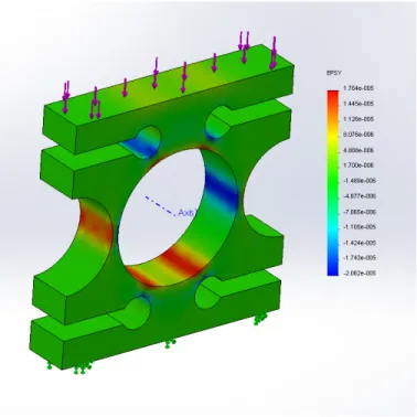
Figure 2.13: Load cell strain simulation in SolidWorks. When a downward force of 9.8 N is applied to the top surface of the load cell, it experiences 14 µS on the outer measurement surfaces and -20µS on the inner measurement surfaces. Warmer colors correspond to tensile strains and cooler colors correspond to compressive strains.
Figure 2.14: Load cell frequency study in SolidWorks. The figure shows the exagger-ated main deformation mode (mode no. 1 in table 2.1) of the load cell that produces a resonant frequency of 540 Hz. Warmer colors correspond to greater displacement.
Figure 2.15: Load cell gage locations. The yellow blocks represent the mounting locations of the Omega KFG-10-120-C1-11L1M2R strain gages. The gages are enu-merated with their symbolic resistances in a full-bridge configuration consistent with the terminology of figure 2.12.
2.4.3
Measurement Results
Instead of testing both wings simultaneously, only one was tested at a time for two
reasons. First, the flapping platform was able to drive a single wing at higher
wing-beat frequencies compared to both wings, enabling a wider range of test conditions.
Second, differences in the Mk3 joint behavior in the wing pair caused significant,
vi-sually observable differences in wing flexion and extension angles. To compensate for
these differences, subtle adjustment of the joint spring preloads was required. In order
to remove as many confounding variables as possible and achieve more meaningful
measurements, it was better to simply perform testing with a single wing. Preliminary
evaluation of the flapping platform with the Polulu motor controller did not allow
driving of the wings at the desired wingbeat frequencies due to its current sourcing
limitations. Instead, the terminals of the DC drive motor were connected directly to
the outputs of a regulated bench-top power supply and the wings were driven at the
voltages listed in tables 2.3 and 2.4.
National Instruments hardware and software was used to amplify, filter and record
data from the output of the load cell’s Wheatstone bridge. The data acquisition
schematic is shown in figure 2.16. The SCXI-1600 strain gage module was configured
to record output from the full-bridge at sampling frequency of 1 kHz and apply a
fourth-order Butterworth low-pass filter with a 100 Hz cutoff to decrease noise. This
configuration was made with the assumption that the signal components of interest
all resided below 100 Hz. To convert the recorded data to forces, calibration weights
up to 100 g were placed on the load cell to yield a conversion factor between the units
of strain reported by LabVIEW SignalExpress and milliNewton (mN) force.
The effect of four different spring constants (table 2.2) on the flapping performance
at varying driving voltages were analyzed. The results obtained from the test setup
are somewhat surprising. Unexpectedly, table 2.4 shows the rigid wings consistently
SCXI-1000 Chassis SCXI-1600 SCXI-1520 SCXI-1314 LabVIEW SignalExpress
Figure 2.16: Data acquisition flowchart. The output of the Wheatstone bridge con-nects to the SCXI-1314 adapter, which interfaces with the SCXI-1520 strain gage input module. The strain gage module communicates via the SCXI-1000 chassis with the SCXI-1600 USB data acquisition module, which in turn outputs data to a computer running LabVIEW SignalExpress.
generated low-levels of positive lift across flapping conditions. Most unusual are the
highly negative average lift values observed for the 2 V and 3 V driving conditions
across spring stiffnesses. This points a source of systematic error in the measurement
procedure, as there is no logical reason for why this should occur. Aside from this, the
results of springs,k3andk4hint at fact that the spring constant needs to tightly tuned
to either the driving forces or wingbeat frequency, or both. This finding is consistent
with the results of the simulation in Section 2.2. Improvement and debugging of the
load cell hardware and data acquisition stages of this experimental setup are required
to continue analysis.
k1 k2 k3 k4
0.6 1.2 2.1 3.0
Table 2.2: Spring constants (lbs/in) used for wing testing.
Wing Configuration
Vdrive rigid k1 k2 k3 k4
2 V 3.2 3.2 3.2 3.2 3.2 3 V 4.6 4.9 4.9 4.9 4.4 4 V 5.9 6.1 6.1 5.4 5.9 5 V 6.8 n/a n/a 7.0 6.9
Table 2.3: Wingbeat frequency (Hz) vs driving voltage (Vdrive)
Wing Configuration
Vdrive rigid k1 k2 k3 k4
2 V 18 -128 -115 -85 -122 3 V 39 -72 -84 -82 -120 4 V 12 -68 -7 58 -67 5 V 30 n/a n/a -30 95
Table 2.4: Average lift (mN) vs driving voltage (Vdrive)
Chapter 3
Discussion
3.1
Further Testing
The measurements made in Section 2.4.3 are flawed and far from exhaustive. Even
so, there are testing modifications that can be made to improve measurement of the
variables that have already been analyzed. The response of the ring load cell was
calibrated in one direction with the assumption that it had an equal response along
the opposite axial direction. While this assumption should theoretically hold true,
factors such as asymmetrical placement of the strain gages on the load cell could cause
it to be more sensitive in one direction. The load cell should be calibrated in both
directions to ensure validity of the data. To obtain force measurements of greater
accuracy, the walls of the load cell where the strain measurements occur should be
made thinner to further concentrate the stress and magnify levels of surface strain.
By exhibiting higher strain per unit force, the bridge output will vary more and
exercise the amplification stage over a greater portion of its dynamic range. With a
main resonant frequency of 540 Hz, the load cell structure can tolerate a reduction
of stiffness and lowering of the resonant frequency while still exhibiting resonance far
above the signal frequencies of interest.
So far, only the effects of wingbeat frequency and spring stiffness on average lift
variable that necessitates modification of the test setup to analyze. One option for
measuring thrust is to simply add another load cell oriented along the thrust axis
in series with the existing test setup. While this is theoretically feasible, it relies
heavily on the ability of the load cells to reject off-axis forces from affecting their
output. A potential alternative to the series arrangement is to allow the flapping
platform to float along the lift (Z) and thrust (Y) axes and perform the respective
force measurements in parallel. This could be accomplished by building a testing stage
where the flapping platform is allowed to move within the YZ plane using a system
of linear bearings and springs [16]. A test stage such as this could be placed within a
wind tunnel section to enable thrust and lift measurements at varying wind speeds,
adding another dimension of data for analysis. Within this new testing paradigm, the
angle of the flapping platform relative to the direction of airflow could be modified
to investigate the effect of angle of attack of articulated, flapping wings on lift and
thrust production. Finally, with the integration of high speed video, the new data
could be correlated with the wingbeat phase to uncover how the wing is generating
lift and thrust.
3.2
Wing Design Improvements
To improve wing performance, it may be worth revisiting the shim-based flexure hinge
concept. One of the main problems with the Mk3 hinge was flapping differences within
the wing pair caused by variability in part clearances between individual barrel hinges.
Each barrel hinge is composed of three separate parts: the two hinge halves and the
pin. Small differences in the dimensioning of any two mating parts lead to enough
of a difference in the behavior of the joint to cause the wings to perform differently.
Because the flexure hinge is a monolithic element, geometric tolerancing is a non-issue
and would yield more consistent joint performance. A redesign of the wing structure
would be needed to couple it in a lightweight manner to the shim-based hinge.
Taking inspiration from the Festo SmartBird [6], one possibility could be to
ma-chine the structure out of laminated carbon fiber sheets. The carbon sheeting would
provide a convenient, flat surface onto which a flexure element could be bonded with
adhesives. To reduce stress concentration at the bonding site, one could design the
flexure to be thicker along the mounting edges and transition to a thin, flexing section
in the middle. Instead of laminating the structure with a thin membrane to construct
the wing surface, thin carbon sheets could be arranged perpendicularly along the wing
structure to produce an airfoil cross section. The entire wing could be enveloped in
a flexible polyurethane film sleeve, such as Epurex’s PlatilonU [17], with allowances
for movement of the joint. A wing cross section more similar to the ones observed
in nature could make a dramatic difference in performance. To optimize the flapping
performance over a range of wingbeat frequencies, a servo-pulley system could
dy-namically adjust the spring preload within the joint by relaxing the preload at lower
frequencies and tightening it at higher ones. Lastly, eliminating the abrupt contact
forces resulting from full extension at the end of upstroke is critical to lessening wear
and improving efficiency of the wing. It may be possible to cushion the contact with
a deformable material and store the left over kinetic energy of the extending wing in
elastic deformation of wing structure. The potential energy could then be released as
the wing enters its downstroke.
3.3
Conclusion
A pair of passively articulated ornithopter wings were successfully designed and
con-structed. The flexing wing concept exhibited lift performance greater than that of
rigid wings under test configurations where the wingbeat frequency matched well
with the joint spring constant. While this is a step in the right direction, the wings
I built are still a far cry from resembling the wings seen in nature. Extended testing
combined with significant modifications to the wing design are necessary to further
explore the viability of passively articulated wings.
Bibliography
[1] K. Schmidt-Nielsen. Scaling: Why is Animal Size so Important?, chapter 6. Cambridge University Press, London, 1984.
[2] V. A. Tucker. Respiratory exchange and evaporative water loss in the flying budgerigar. J. Exp. Biol., 1968.
[3] M. Hildebrand. Form and function in vertebrate feeding and locomotion. Am. Zool., 28:727–738, 1988.
[4] F. W. Headley. The structure and life of birds, chapter 7. Macmillan, London, 1895.
[5] H. I. Fisher. Bony mechanism of automatic flexion and extension in the pigeon’s wing. Science, 1957.
[6] Festo. Smartbird – bird flight deciphered. http://www.festo.com/cms/en_ corp/9462.htm, 2011.
[7] R. Sterchak. Ornithopter having a wing structure and mechanism for imparting realistic, bird-like motion thereto, 2009.
[8] J. M. Harris. Articulated wing ornithopter, 1979.
[9] L. Birglen. From flapping wings to underactuated fingers and beyond: a broad look at self-adaptive mechanisms. Mech. Sci., 2010.
[10] R. H. J. Brown. The flight of birds: the flapping cycle of the pigeon. J. Exp. Biol., 25:322–333, 1948.
[11] T. L. Hedrick, J. R. Usherwood, and A. A. Biewener. Wing inertia and whole body acceleration: an analysis of instantaneous aerodynamic force production in cockatiels (nymphicus hollandicus) flying across a range of speeds. J. Exp. Biol., 207:1689–1702, 2004.
[12] HobbyTron. Cybird - 2 Channel Electric RC Ornithopter. http://www. hobbytron.com/Cybird2ChannelElectricRCOrnithopter.html#reviews, 2012.
[13] Kazuhito Kakuta. Ornithopter and Ultra small airplanes. http://homepage2. nifty.com/smark/HabatakE.htm, 2011.
[14] Rhdv. File:Wheatstonebridge.svg. Available from Wikimedia Commons, http: //en.wikipedia.org/wiki/File:Wheatstonebridge.svg, 2007.
[15] James Pierson. Load / Force Cells. http://www.sensorland.com/HowPage005. html, 2001.
[16] J. Gautam. The development of a miniature flexible flapping wing mechanism for use in a robotic air vehicle. Master’s thesis, Georgia Tech, 2007.
[17] Epurex. Platilon u. http://www.epurex.com/fileadmin/downloads/ Platilon_U_EN_2012-02.pdf, 2012.

![Figure 2.12: Wheatstone bridge [14]. A DC potential is applied across A and C to yield the output, V G](https://thumb-us.123doks.com/thumbv2/123dok_us/8295906.2196947/24.918.197.719.142.653/figure-wheatstone-bridge-dc-potential-applied-yield-output.webp)