Wireless-Powered Cooperative Spectrum
Sharing Networks with Full-Duplex and
NOMA Transmissions
Azar Hakimi
Faculty of Engineering SKU University Shahrekord, Iran [email protected]
Mohammadali Mohammadi
*, Zahra Mobini
Faculty of EngineeringSKU University Shahrekord, Iran
{m.a.mohammadi, z.mobini}@sku.ac.ir Received: 10 August 2018 - Accepted: 22 April 2019
Abstract— We consider a non-orthogonal multiple access (NOMA) cooperative spectrum sharing network, where a multi-antenna secondary transmitter assists transmission of a primary transmitter-receiver pair, and at the same time transmits to a secondary receiver. The secondary transmitter is assumed to be full-duplex and energy-constrained. Therefore, secondary transmitter replenishes its battery storage via energy harvesting from an energy access point located in its vicinity. In order to cancel the self-interference at the secondary transmitter, two zero-forcing (ZF)-based beamforming schemes and one maximum ratio combining/maximum ratio transmission (MRC/MRT) scheme are designed. Then, corresponding outage probability analysis of the primary and secondary networks with proposed beamforming schemes are derived. Outage probability results are used to study the delay-constrained throughput of the system. Our results suggest that by utilizing ZF-based beamforming schemes, significant performance improvement can be achieved compared to the half-duplex counterpart. Moreover, our results indicate that proposed ZF-based schemes achieves a zero-diversity order.
Keywords-component; Non-orthogonal multiple access (NOMA); cooperative spectrum sharing networks; full-duplex, delay-constrained throughput; zero-forcing beamforming.
I. INTRODUCTION
Full-duplex (FD) communication, which is potentially able to double the spectral efficiency as compared with the half-duplex (HD) counterpart, has been recently touted as a promising technology in the emerging wireless communication systems such as fifth generation (5G) cellular networks due to its potential [1]. However, the key challenge in practical FD systems is the residual self-interference (SI) which considerably limits its application [2]. To overcome the
* Corresponding Author
SI, several analog and digital domain SI cancellation techniques have been proposed in the literature [1]. Analog domain SI suppression is performed using passive isolation techniques such as placing radio frequency (RF) absorber material between antennas and use of narrow beam width directional antennas [2]. Digital SI cancellation is applied after analog SI cancellation reduce the SI signals as low as the receiver noise floor. Recent advances in SI cancellation methods have made FD transceivers feasible in practice. Specifically, single antenna FD
implementations rely on analog SI cancellation, digital SI cancellation, and antenna based SI suppression [3]. In case of multi-antenna systems, spatial suppression through applying zero-forcing (ZF), null-space projection and antenna selection has received a lot of research interest to efficiently suppress/cancel SI [4]-[6].
Cognitive radio (CR) is another promising candidate to improve the spectral efficiency of the future mobile communication system. In the CR networks, secondary users (SUs) can access the primary users’ (PUs) licensed spectrum via underlay or overlay strategies [7]. In the underlay strategy, the SUs are allowed to transmit over PUs spectrum as long as they meet the interference constraint of the PUs. In overlay networks, SUs cooperatively assists the PUs and in return they are allowed to simultaneously transmit over the licensed spectrum [8]. Furthermore, by adopting FD nodes, remarkable improvement in spectral efficiency over CR networks can be achieved [9]. A survey of research on FD enabled CR networks has been provided in [10].
On the other hand, non-orthogonal multiple access (NOMA) has gained more attention as a candidate multiple access technique in 5G for simultaneously serving multiple users over the same spectrum [11]-[14]. Users that are exposed to lack of spectrum or have week channel conditions can cooperate with NOMA users and transmit over the same spectrum. NOMA techniques are primarily classified into two categories, namely, code-domain NOMA and power-domain NOMA [12]. Power-domain NOMA multiplexes multiple users at the transmitter with different power levels and deploys multiuser detection algorithms such as successive interference cancellation (SIC) at the receivers to decode the received signals. The integration of NOMA with CR networks has been investigated in a few recent studies [15]-[18]. Specifically, the authors in [15] investigated multicast/unicast transmissions in a downlink CR-NOMA system. The authors in [16] studied the application of NOMA in large-scale CR networks by using tools from stochastic geometry. A cooperative mechanism for a NOMA-assisted multicast CR network has been proposed in [17]. In [18], a cooperative NOMA system was analyzed wherein an access point (AP) communicates to one SU via the help of a dedicated FD multi-antenna relay, while at the same time the AP directly transmits to a SU.
Meanwhile, energy efficiency is also an important concern in 5G [19]. In this regard, radio frequency (RF) energy harvesting is a promising approach to improve the energy efficiency, where directed RF signals are used to power the wireless devices [20]. In this context, two main approaches have been investigated in the literature known as (ii) simultaneous wireless information and power transfer (SWIPT) and (i) wireless power transfer (WPT). WPT refers to case where dedicated external energy sources such as energy access point (EAP) are deployed to power wireless devices, while in SWIPT, source’s signal conveys both energy and information to the constraint receiver. Performance of an
energy-constrained cooperative NOMA system has been studied in [21], at which NOMA near user is wirelessly powered to relay the far user’s information. A wirelessly-powered NOMA system has been studied in [22], where an FD transmitter harvests energy from a dedicated energy source and its own loop channel, while transmits information to the NOMA users at the same time.
Motivated by the energy efficiency and energy efficiency requirements of the 5G wireless networks we integrate the FD communications, NOMA technique, and WPT into cooperative spectrum sharing network. Specifically, an energy-constraint FD multi-antenna secondary transmitter (STx) is deployed as a relay to serve both primary-receiver (PRx) and secondary-receiver (SRx) at the same time by using NOMA transmission. STx powers its battery storage from RF signals transmitted by a dedicated EAP. The main contributions of this paper are as follows:
We propose two zero forcing (ZF)-based beamforming designs to mitigate the SI at the FD STx. Delay-constrained throughput expressions for the proposed beamforming designs are derived. Furthermore, we develop the system’s delay-constrained throughput of a benchmark scenario, where maximum ratio combining (MRC) and maximum ratio transmission (MRT) principles are used the receive and transmit beamformer design.
High signal-to-noise ratio (SNR) approximations of the outage probability are presented for the proposed beamforming designs, which facilitate gaining insights into the impact of the system parameters on the system performance.
We further analyze the HD spectrum sharing counterpart in terms of the outage probability and delay-constraint throughput, to illustrate the gains achieved by the FD operation.
Notation: Bold upper case letters are used to denote matrices; bold lower case letters are used to denote vectors. The superscripts (⋅)𝑇, (⋅)†, (⋅)∗, and ‖ ⋅ ‖ stand
for transpose, conjugate transpose, conjugate, and the Euclidean norm of the vector, respectively; Pr(𝐴)
denotes the probability of event 𝐴; 𝐴̄ denotes the complementary event of 𝐴; 𝐹𝑋(⋅) and 𝑓𝑋(⋅) denote the
cumulative distribution function (cdf) and probability density function (pdf) of the random variable (RV) 𝑋, respectively; 𝔼{𝑥} stands for the expectation of the random variable 𝑥; 𝒞𝒩(0, 𝜎2) denotes a circularly
symmetric complex Gaussian RV 𝑥 with variance 𝜎2;
Γ(𝑎) is the Gamma function; Γ(𝑎, 𝑥) and 𝛾(𝑎, 𝑥) is upper incomplete and lower incomplete Gamma function, respectively [23, Eq.(8.350)]; 𝐾𝜈(⋅) is the 𝜈th
order modified Bessel function of the second kind [23, Eq. (8.432)]; 𝑊𝜆,𝜇(⋅) is the Whittaker function [23, Eq.
(9.222)]
II. SYSTEMMODEL
As illustrated in Fig. 1, we consider a spectrum sharing network in which a PTx and an STx communicate with their receivers PRx and SRx, respectively. However, due to the high path-loss and
Fig 1. System model.
heavy shadowing, direct link between the PTx and the PRx is not available. It is assumed that the STx acts as an intermediate node and relays the primary message, and instead, it simultaneously reaches the spectrum by using NOMA. In other words, using NOMA allows the STx to serve both PRx and SRx at the same time and on the same channel. Each node is equipped with a single antenna, except the STx that is equipped with 𝑁𝑇
antennas to transmit signals and 𝑁𝑅 antennas to receive
signals. Besides, we consider that the STx is an energy-constrained node and refills its battery via a dedicated EAP. For this purpose, the STx employs a time-switching (TS) protocol [6]. We further assume that the PRx is located in the vicinity of the STx at distance 𝑑3,
while the SRx is located far from the STx at distance
𝑑4 (𝑑4> 𝑑3).
All network’s channels are assumed to undergo flat Rayleigh fading. Therefore, all channels remain constant during each block of transmission but vary independently over different blocks. Let 𝐡1∈ 𝒞𝑁𝑅×1,
𝐡2∈ 𝒞𝑁𝑅×1, 𝐡3∈ 𝒞𝑁𝑇×1, and 𝐡4∈ 𝒞𝑁𝑅×1 denote the
channel spanning from EAP to STx, from PRx to STx, from STx to PRx, and from STx to SRx, respectively. The entries of 𝐡𝑖, 𝑖 ∈ {1,2,3,4} are assumed to be
independent identically distributed (i.i.d) zero mean complex Gaussian RVs with variance 𝛽ℎ𝑖, which
models the path loss effect for the corresponding link. A. Energy Harvesting Phase
The first phase of transmission is devoted to harvesting energy at the STx using TS protocol. At 𝛼
fraction of the transmission block time 𝑇, i.e., 𝛼𝑇, the STx harvests energy from the EAP, where 0 ≤ 𝛼 ≤ 1. Hence, during the first phase the received signal at the STx can be expressed as
𝑦ST,1[𝑖] = √𝛽ℎ1𝑃EA𝐰𝐸†𝐡1𝑥𝑒[𝑖] + 𝐰𝐸†𝒏ST[𝑖], (1)
where 𝑃EA denotes the EAP’s transmit power, 𝑥𝑒[𝑖] is
the energy symbol transmitted from EAP, 𝐰𝐸∈ 𝒞𝑁𝑅×1
is the energy beamformer at the STx, and 𝒏ST[𝑖] ∼
𝒞𝒩(0, 𝜎ST2 𝑰𝑁𝑅) denotes the additive white Gaussian noise (AWGN) at STx.
Similar to [6], we ignore the amount of harvested energy from the noise. Thus, the harvested energy and
subsequently the transmit power at the STx are obtained as
𝐸ST= (𝜂𝛽ℎ1𝑃EA|𝐰𝐸†𝐡1|2)𝛼𝑇, (2)
and
𝑃ST= 𝜅𝛽ℎ1𝑃EA|𝐰𝐸†𝐡1|2, (3)
respectively, where 𝜅 =1−𝛼𝜂𝛼 and 𝜂 denotes the RF-to-DC conversion efficiency. It can readily show that the optimal 𝐰𝐸 in order to maximize the harvested power
at the STx, is 𝐰𝐸=‖𝐡𝐡1
1‖, which results in 𝑃ST=
𝜅𝛽ℎ1𝑃EA‖𝐡1‖2.
B. Information Transfer Phase
In the information transfer phase, PTx sends its message to the STx in the remained time, (1 − 𝛼)𝑇. Therefore, during the second phase, the received signal at the STx can be expressed as
𝑦ST,2[𝑖] = √𝛽ℎ2𝑃PT𝐰𝑟
†𝐡
2𝑥PR[𝑖] + 𝐰𝑟†𝐇SI𝐰𝑡𝑥𝑅[𝑖]
+𝐰𝑟†𝒏ST[𝑖], (4)
where 𝑃PT is the transmit power of PTx, 𝐰𝑟∈ 𝒞𝑁𝑅×1
and 𝐰𝑡∈ 𝒞𝑁𝑇×1 are the receiver and transmit
beamformers at the FD STx, respectively, and 𝑥PR[𝑖]
is the transmit signal of the PTx. 𝑥𝑅[𝑖] =
√𝑎1𝑃ST𝑥PR[𝑖] + √𝑎2𝑃ST𝑥SR[𝑖] denotes the
superimposed signal that the STx, transmits to the receivers where 𝑥SR[𝑖] is the information symbol
intended for SRx, 𝑃ST is the transmit power of STx, and
𝑎𝑖 are the power allocation coefficients, such that 𝑎1+
𝑎2= 1 and 𝑎1< 𝑎2 (since we assume that SRx is
located farther to STx than PRx and needs more power allocation coefficient to decodes its message). Similar to [4], we model the elements of the 𝑁𝑅× 𝑁𝑇 SI
channel 𝐇SI as i.i.d. 𝒞𝒩(𝑜, 𝜎SI2) RVs.
Accordingly, the received signal-to-interference-plus-noise ratio (SINR) at the STx can be written as
𝛾
ST=
𝛽ℎ2𝑃𝖯𝖳|𝐰𝑟†𝐡2|2 𝜅𝛽ℎ1𝑃EA‖𝐡1‖2|𝐰†𝑟𝐇SI𝐰𝑡|2+𝜎ST2.
(5) Eq. (5) represents the required SINR at the STx to decode PTx’s information. Then, the STx superimposes its message with PTx’s information decoded at the STx and transmits it to the PRx and SRx. In Eq. (5) we used the fact that 𝔼{𝑥PR𝑥PR∗ } =
𝔼{𝑥SR𝑥SR∗ } = 1. As a result, in the second phase, PRx
and SRx receive signals as following
𝑦PR[𝑖] = √𝛽ℎ3𝑃ST𝐡𝑇3𝐰𝑡𝑥𝑅[𝑖] + 𝑛PR[𝑖], (6) and
𝑦SR[𝑖] = √𝛽ℎ4𝑃ST𝐡𝑇4𝐰𝑡𝑥𝑅[𝑖] + 𝑛SR[𝑖], (7) respectively, where 𝑛PR[𝑖] ∼ 𝒞𝒩(0, 𝜎PR2 ) and
𝑛SR[𝑖] ∼ 𝒞𝒩(0, 𝜎SR2 ) are AWGN at the PRx and the
SRx, respectively. Based on NOMA principals, successive interference cancellation (SIC) is performed at the PRx, since it has better channel condition, in order to detect and subtract its counterpart message from its received signal. Then, PRx decodes
its own message from the remained signal. Thus, the received SINR at the PRx to detect SRx’s message,
𝑥SR, is given by
𝛾
PR,𝑥SR=
𝛽ℎ3𝛽ℎ1𝑎2𝜅𝑃EA‖𝐡1‖2|𝐡3𝑇𝐰𝑡|2𝛽ℎ3𝛽ℎ1𝑎1𝜅𝑃EA‖𝐡1‖2|𝐡3𝑇𝐰𝑡|2+𝜎PR2
.
(8)Consequently, the desired information of PTx can be achieved after decoding and subtracting the 𝑥SR from
the received signal at the PTx. Thus, the desired SNR at PRx for decoding its own signal is given by
𝛾PR=
𝛽ℎ3𝛽ℎ1𝑎1𝜅𝑃EA
𝜎PR2 ‖𝐡1‖ 2|𝐡
3 𝑇𝐰
𝑡|2. (9)
Based on the NOMA nature, the user that suffers poor channel condition considers its counterpart message as interference and decodes its message. Subsequently, the required SINR at the SRx to decode its massage is as following
𝛾SR=
𝛽ℎ4𝛽ℎ1𝑎2𝜅𝑃EA‖𝐡1‖2|𝐡4𝑇𝐰 𝑡|2
𝛽ℎ4𝛽ℎ1𝑎1𝜅𝑃EA‖𝐡1‖2|𝐡4𝑇𝐰𝑡|2+𝜎SR2 . (10)
III. BEAMFORMINGDESIGN
In this section, we provide low complexity joint receive/transmit beamforming designs for end-to-end SINR maximization. Specifically, based on ZF SI cancellation, receive/transmit beamforming vectors at the STx are designed [5], [6].
A. TZF Scheme
We apply MRC at the STx input, i.e., 𝐰𝑟MRC=‖𝐡𝐡2
2‖ and then by substituting 𝐰𝑟MRC into (5), the transmit
beamforming vector at the STx can be obtained using the ZF criterion such that
max
‖𝐰𝑡‖=1| 𝐡3 𝑇𝐰
𝑡|2,
s. t 𝐡2†𝐇SI𝐰t= 0. (11)
Following similar steps in [6], it can be readily checked that 𝐁 ≜ 𝐇SI†𝐡2𝐡2†𝐇SI is a rank-one Hermitian matrix
with eigenvalue 𝜆 ≜ ‖𝐡2†𝐇SI‖2 and eigenvector 𝒙 ≜ 𝐇SI†𝐡2
‖𝐇SI†𝐡2‖. Accordingly, by using the eigenvalue decomposition of 𝐁 , i.e., 𝒙†(𝑰 −1
𝜆𝐁) = 0 we get
𝒙†(𝑰 −1
𝜆𝐁) 𝐰̄𝑡= 0 for all 𝐰̄𝑡≠ 𝟎. Comparing this
with the ZF constraint in (11), we obtain 𝐰𝑡= 𝐂𝐰̄𝑡,
where 𝐂 = 𝑰𝑁𝑇−
𝐇SI†𝐡2𝐡2†𝐇SI
‖𝐡2†𝐇SI‖2 , without violating the ZF constraint. Therefore, the objective function in (11) reduces to |𝐡3𝑇𝐂𝐰̄𝑡|2 which is maximized with 𝐰̄𝑡=
𝑘𝑐𝐂𝐡3∗. Note that 𝐂 is an idempotent matrix and hence
𝐂 = 𝐂2. Moreover, since ||𝐰
𝑡|| = 1, it is clear that
𝑘𝑐=‖𝐂𝐡1
3∗‖. Consequently, the transmit beamformer for the TZF scheme is
𝐰𝑡ZF=
𝐂𝐡3∗
‖𝐂𝐡3∗‖. (12)
B. RZF Scheme
With RZF scheme, we set 𝐰𝑡 according to MRT
concept, i.e., 𝐰𝑡MRT = 𝐡3
∗
‖𝐡3∗‖, and then by plugging it into (5), the receive beamformer 𝐰𝑟 can be obtained by
solving
max
‖𝐰𝑟‖=1| 𝐰𝑟 †𝐡
2|2,
s. t 𝐰𝑟†𝐇SI𝐡3∗ = 0. (13)
By using similar steps as in the TZF design, the combining vector 𝐰𝑟 is obtained as
𝐰𝑟ZF=
𝐃𝐡2
‖𝐃𝐡2‖, (14)
where 𝐃 = 𝑰𝑁𝑅−
𝐇SI𝐡3∗𝐡3𝑇𝐇SI† ‖𝐇SI𝐡3∗‖2 . C. MRC/MRT Scheme
As an alternative beamforming design, we consider MRC/MRT scheme, where receive and transmit beamforming vectors are matched to the receive and transmit link at the STx. Mathematically speaking, the receive and transmit beamforming vectors with MRC/MRT scheme are set as
𝐰𝑟MRC=‖𝐡𝐡2
2‖, and 𝐰𝑡
MRT= 𝐡3∗
‖𝐡3∗‖, (15) respectively. It is worth mentioning that MRT/MRC scheme is suitable for low complexity FD systems as they do not need to estimate the SI channel. Moreover, MRT/MRC scheme is preferred for HD scenarios and hence it is interesting to characterize its achievable performance in the FD case [24].
IV. PERFORMANCEANALYSIS
In this section, we characterize the performance of the primary and secondary networks with proposed beamforming designs. Specifically, we derive the delay-constrained throughput of the system and derive outage probability expressions.
A. Delay-Constrained Throughput
We consider the delay-constrained scenario, where the source transmits at a constant rate 𝑅𝑐 bits/sec/Hz. The
average delay-constrained throughput of the primary and secondary networks with proposed beamforming schemes can be computed as [6]
𝑅𝐷,PUi = (1 − Pout,PUi )𝑅𝒄(1 − 𝛼), (16)
and
𝑅𝐷,SUi = (1 − Pout,SUi )𝑅𝒄(1 − 𝛼), (17)
where Pout,PUi and Pout,SUi are the outage probability of
the primary and secondary networks, respectively, and
i ∈ {TZF, RZF, MRC, HD}. Therefore, in order to evaluate the delay-constrained throughput of the considered system, we need to derive the exact outage probability of the system. In the following, we provide outage probability expressions for the primary and
secondary networks, which are used to drive the delay-constrained throughput.
B. Outage Probability Analysis
Outage probability is an important performance metric for wireless networks, which is defined as the probability that the instantaneous SINR falls below a predefined threshold. Let 𝜃1= 2ℛ1− 1 and 𝜃2=
2ℛ2− 1, where ℛ
1 and ℛ2 are the transmission rates
at primary and secondary networks, respectively. An outage event at the primary network occurs when STx fails to decode 𝑥PR (A1𝑖), or STx can decode 𝑥PR
but PRx detect 𝑥SR incorrectly (A𝑖2), or PRx detect 𝑥SR
but decode 𝑥PR incorrectly (A𝑖3). Therefore, the outage
probability of the PRx can be mathematically expressed as
Pout,PUi = 𝒫1𝑖+ (1 − 𝒫1𝑖)(1 − 𝒫2𝑖), (18)
where i ∈ {TZF, RZF, MRC}, 𝒫1𝑖= 𝐏𝐫(A1𝑖) and 𝒫2𝑖=
𝐏𝐫(A̅𝑖2⋂A̅𝑖3).
Furthermore, the outage event at the SRx is happened when the SRx’s SINR falls below a predetermined threshold, 𝜃2, which is mathematically expressed as
Pout,SUi = 𝐏𝐫(𝛾SR𝑖 < θ2). (19)
In what follows, we present key results for the outage performance of the system with proposed beamforming schemes.
1) TZF Scheme
By Substituting 𝐰𝑡ZF into (8) and (9), the SINR 𝛾PR,𝑥SR
TZF
and 𝛾PRTZFare respectively given by
𝛾PR,𝑥TZFSR= 𝑐0‖𝐡1‖
2‖𝐡̃3‖2
𝑐1‖𝐡1‖2‖𝐡̃3‖2+𝜎
PR2 , (20)
𝛾PRTZF=𝜎𝑐1
PR2 ‖𝐡1‖
2‖𝐡̃
3‖2. (21)
By substituting 𝐰𝑟MRC and 𝐰𝑡ZF into (5), the SINR
𝛾STTZF= 𝑐2‖𝐡2‖2 is obtained. Where 𝑐0=
𝛽ℎ3𝛽ℎ1𝑎2𝜅𝑃EA, 𝑐1= 𝛽ℎ3𝛽ℎ1𝑎1𝜅𝑃EA, and 𝑐2= 𝛽ℎ2𝜌PT with 𝜌PT=𝑃𝜎PT
ST2 . The main result for TZF design is provided in the following proposition.
Proposition 1: The exact outage probability of the primary network with the TZF design at the FD STx, is obtained as
Pout,PUTZF = 𝑃 (𝑁𝑅,𝜃𝑐2
2) + Q (𝑁𝑅,
𝜃2
𝑐2) (1 −
Γ(𝑁2
𝑅)∑
𝜇𝑁𝑅+𝑚2
𝑚! 𝑁𝑇−2
𝑚=0 𝐾𝑁𝑅−𝑚(2√𝜇)). (22)
where 𝑃(a, 𝑥) =𝛾(𝑎,𝑥)Γ(𝑎), Q(a, 𝑥) =Γ(𝑎,𝑥)Γ(𝑎), and 𝜇 = max ( 𝜎PR2 𝜃1
𝑐0−𝑐1𝜃1, 𝜎PR2 𝜃1
𝑐1 ).
Proof: See Appendix A. ∎
We now look into the high SNR regime to get more insights on the system design.
Proposition 2: In the high SNR regime, i.e., 𝜌PT → ∞,
the outage probability of the primary network with the TZF design can be approximated as
Pout,PU∞,TZF≈ 1 − ( 2 Γ(𝑁𝑅)∑
𝜇𝑁𝑅+𝑚2
𝑚! 𝑁𝑇−2
𝑚=0 𝐾𝑁𝑅−𝑚(2√𝜇)) ×
(1 − ΨTZF(𝜌1
PT)
𝑁𝑅
)
𝜌PT → ∞
→ 1 − (
2 Γ(𝑁𝑅)∑
𝜇𝑁𝑅+𝑚2
𝑚! 𝑁𝑇−2
𝑚=0 𝐾𝑁𝑅−𝑚(2√𝜇)), (23) where ΨTZF=Γ(𝑁1
𝑅+1)(
𝜃2
𝛽ℎ2) 𝑁𝑅
.
Proof: See Appendix B. ∎
Proposition 2 indicates that the TZF scheme achieves a floor at high SNR regime and thus exhibits a zero-diversity order behavior.
In order to derive the outage performance of the secondary network, we first need to obtain 𝛾SRTZF. To
this end, by substituting 𝐰𝑡TZF into (10), 𝛾SRTZF can be
derived as
𝛾
SRTZF=
𝑐3‖𝐡1‖2|𝐡4T𝐰𝑡ZF| 2 𝑐4‖𝐡1‖2|𝐡T4𝐰𝑡ZF|2+𝜎SR2,
(24) where 𝑐3= 𝛽ℎ4𝛽ℎ1𝑎2𝜅𝑃EA, and 𝑐4= 𝛽ℎ4𝛽ℎ1𝑎1𝜅𝑃EA. Proposition 3: The exact outage probability of the secondary network with the TZF design can be obtained asPout,SUTZF = 1 −2𝜉
𝑁𝑅 2
Γ(𝑁𝑅)𝐾𝑁𝑅(2√𝜉). (25) where 𝜉 = 𝜎SR2 𝜃2
𝑐3−𝑐4𝜃2.
Proof: See Appendix C. ∎
2) RZF Scheme
By Substituting 𝐰𝑡MRT into (8) and (9), the SINR
𝛾PR,𝑥RZFSR and 𝛾PRRZF are respectively given by
𝛾PR,𝑥RZFSR= 𝑐0‖𝐡1‖
2‖𝐡3‖2
𝑐1‖𝐡1‖2‖𝐡3‖2+𝜎PR2 , (26)
𝛾PRRZF= 𝑐1 𝜎PR2 ‖𝐡1‖
2‖𝐡
3‖2. (27)
Moreover, by substituting 𝐰𝑟ZF and 𝐰𝑡MRT into (5), the
SINR at the STx is obtained as
𝛾STRZF= 𝑐2‖𝐡̃2‖2. (28)
In the following the outage analyses of RZF scheme is provided.
Proposition 4: The exact outage probability of primary network with RZF design is obtained as
Pout,PURZF = 𝑃 (𝑁𝑅− 1,𝜃𝑐2
2) + Q (𝑁𝑅− 1,
𝜃2
𝑐2) (1 −
Γ(𝑁2
𝑅) ∑
𝜇𝑁𝑅+𝑚2
𝑚! 𝑁𝑇−1
𝑚=0 𝐾𝑁𝑅−𝑚(2√𝜇)). (29)
Proof: Proof follows similar steps to the proof of
Proposition 1 and thus has been omitted due to space limitation. ∎
To get more insight about the effect of system parameters, we develop an asymptotic expression for the outage probability of the primary network with RZF scheme.
Proposition 5: The outage probability of the primary network with RZF scheme in the high SNR regime, i.e., 𝜌PT→ ∞, can be approximated as
Pout,PU∞,TZF≈ 1 − (
2 Γ(𝑁𝑅) ∑
𝜇𝑁𝑅2+𝑚
𝑚!
𝑁𝑇−1
𝑚=0
𝐾𝑁𝑅−𝑚(2√𝜇))
× (1 − ΨRZF(
1 𝜌PT)
𝑁𝑅−1
) 𝜌PT→ ∞
→ 1 − (
2 Γ(𝑁𝑅)∑
𝜇𝑁𝑅+𝑚2
𝑚! 𝑁𝑇−1
𝑚=0 𝐾𝑁𝑅−𝑚(2√𝜇)), (30) where ΨRZF=Γ(𝑁1
𝑅)(
𝜃2
𝛽ℎ2) 𝑁𝑅−1
.
Proof: The proof follows similar steps as in Proposition 2, thus have been omitted. ∎
From (30) we see that the RZF design exhibits a zero-diversity order behavior. Moreover, by comparing (30) and (23), it is clear that RZF scheme outperforms TZF scheme at high SNR regime.
Furthermore, one can readily show that 𝛾SRRZF have the
same statistics as 𝛾SRTZF, and therefore Pout,SURZF = Pout,SUTZF .
3) MRC/MRT Scheme
With this scheme, 𝛾PR,𝑥MRCSR and 𝛾PRMRC are the same as
𝛾PR,𝑥RZFSR and 𝛾PRRZF, respectively. Furthermore, by
substituting 𝐰𝑡MRT and 𝐰𝑟MRC into (5) we have
𝛾
STMRC=
𝑐5‖𝐡2‖2𝑐6‖𝐡1‖2|𝐰𝑟MRC†HSI𝐰𝑡MRT| 2
+𝜎PR2
.
(31) For notational convenience, we define 𝑐5= 𝛽ℎ2𝑃PT and 𝑐6= 𝛽ℎ1𝜅𝑃EA.Proposition 6: The exact outage probability of the primary network with MRC/MRT design is given by
Pout,PUMRC = 𝐼(𝜃2) + (1 − 𝐼(𝜃2)) (1 −
Γ(𝑁2
𝑅)∑
𝜇𝑁𝑅+𝑚2
𝑚! 𝑁𝑇−1
𝑚=0 𝐾𝑁𝑅−𝑚(2√𝜇)),
(32) where 𝐼(𝜃2) =
2 Γ2(𝑁𝑅)∫ (
𝑐5𝑥−𝜃2𝜎ST2 𝜃2𝜎SI2𝑐6 )
𝑁𝑅 2
𝐾𝑁𝑅 ∞
0 (2√
𝑐5𝑥−𝜃2𝜎ST2 𝜃2𝜎SI2𝑐6 ) 𝑥
𝑁𝑅−1×
𝑒−𝑥𝑑𝑥.
Proof: See Appendix D. ∎
Although the integral 𝐼(𝜃2) does not seem to admit a
closed-form solution, it can be evaluated numerically using software packages like Matlab and Mathematica. We now derive a closed-form lower bound on the outage probability of the primary network with MRC/MRT design.
Corollary 1: The outage probability of the primary user with MRC/MRT design is lower bounded as
Pout,PUMRC ≈ 1 − (1 −
Γ(2𝑁𝑅) Γ(𝑁𝑅)(
𝑐5 𝜃2𝜎SI2𝑐6)
𝑁𝑅−1 2 𝑒2𝑐6𝜃2𝜎SI𝑐5 2
× 𝑊1
2− 3 2𝑁𝑅,
𝑁𝑅 2
( 𝑐5 𝜃2𝜎SI2𝑐6)) (
2 Γ(𝑁𝑅)∑
𝜇𝑁𝑅+𝑚2 𝑚! 𝑁𝑇−1
𝑚=0 𝐾𝑁𝑅−𝑚(2√𝜇)). (33) Proof: See Appendix E. ∎
Now, we proceed to calculate Pout,SUMRC . By inspecting
𝛾SRMRC, it can be seen that 𝛾SRMRC has the same statistics
as 𝛾SRTZF, then it can be readily concluded that Pout,SUMRC =
Pout,SUTZF .
V. HALF-DUPLEXTRAMNSMISION
In this section, results for the HD spectrum sharing system is provided. HD system is served as a benchmark to evaluate the performance gains achieved by the FD operation.
In the HD spectrum sharing system, STx is assumed to be HD. We first provide a brief description of the HD spectrum sharing signal model. The energy harvesting phase is the same as the FD spectrum sharing system. For the information transmission phase, the remaining (1 − 𝛼) portion of block time is equally partitioned into two time slots. Thus, the transmit power at the STx can be expressed as
𝑃STHD=
𝐸ST𝛼𝑇
(1 − 𝛼)𝑇 2
, = 𝜅′𝛽
ℎ1𝑃EA‖𝐡1‖2, (34)
where 𝜅′=2𝜂𝛼 1−𝛼.
During the first time slot of the information transmission phase, the received signal at the STx is given by
𝑦ST,2[𝑖] = √𝛽ℎ2𝑃PT𝐰𝑟†𝐡2𝑥PR[𝑖]+𝐰𝑟†𝐇SI𝐰𝑡𝑥𝑅[𝑖]
+𝑛ST[𝑖]. (35)
Therefore, the required SNR at ST to decode the 𝑥PR is
given by
𝛾STHD=
𝛽ℎ2𝑃ST|𝐰𝑟†𝐡2|2
𝜎ST2 . (36)
During the second time slot, STx transmits a superimposed signal to the PRx and SRx. The received signals at PRx and SRx are given by
𝑦PR[𝑖] = √𝛽ℎ3𝑃STHD𝐡3𝑇𝐰𝑡𝑥𝑅[𝑖] + 𝑛PR[𝑖], (37)
and
𝑦SR[𝑖] = √𝛽ℎ4𝑃𝖲𝖳HD𝐡4𝑇𝐰𝑡𝑥𝑅[𝑖] + 𝑛SR[𝑖], (38) respectively. Therefore, the SINR at the PRx for decoding 𝑥SR is given by
𝛾
PR,𝑥HD SR=
𝛽ℎ3𝛽ℎ1𝑎2𝜅′𝑃EA‖𝐡1‖2|𝐡3𝑇𝐰𝑡|2𝛽ℎ3𝛽ℎ1𝑎1𝜅′𝑃EA‖𝐡1‖2|𝐡3𝑇𝐰𝑡|2+𝜎PR2
.
(39)Fig. 2. Outage probability of the primary and secondary networks with TZF and RZF beamforming schemes and for different antenna configurations (𝑃PT=10 dBm).
Moreover, the required SNR at PRx for decoding its information is given by
𝛾PRHD=
𝛽ℎ3𝛽ℎ1𝑎1𝜅′𝑃EA
𝜎PR2 ‖𝐡1‖ 2|𝐡
3 𝑇𝐰
𝑡|2. (40)
Furthermore, the required SINR at the SRx for extracting its own massage is as following
𝛾
SRHD=
𝛽ℎ4𝛽ℎ1𝑎2𝜅′𝑃EA‖𝐡1‖2|𝐡4𝑇𝐰𝑡|2𝛽ℎ4𝛽ℎ1𝑎1𝜅′𝑃EA‖𝐡1‖2|𝐡4𝑇𝐰𝑡|2+𝜎SR2
.
(41) We now analyze the outage probability of primary and secondary networks under HD transmission. We note that in case of HD transmission, the MRC/MRT beamforming design is the optimum scheme. Therefore, the receive and transmit beamformers are designed as𝐰𝑟MRC=‖𝐡𝐡2 2‖,
𝐰𝑡MRT = 𝐡3
∗
‖𝐡3∗‖. (42)
In the following, we present the results for the HD transmission mode.
Proposition 7: The outage probability of primary user in HD mode is given by
Pout,PUHD,MRC= 𝑃 (𝑁𝑅,
𝜃1
𝑐2) + Q (𝑁𝑅,
𝜃1
𝑐2)
× (1 − Γ(𝑁2
𝑅)∑
𝜇′𝑁𝑅+𝑚2
𝑚! 𝑁𝑇−1
𝑚=0 𝐾𝑁𝑅−𝑚(2√𝜇′)). (43)
where 𝜇′= 𝐦𝐚𝐱 ( 𝜎PR2 𝜃1
2𝑐0−2𝑐1𝜃1,
𝜎PR2 𝜃1 2𝑐1 ).
Proof: The proof of this proposition follows the same approach as proof of Proposition 1, thus it’s been omitted. ∎
1 Optimizing NOMA power allocation coefficients dynamically according to the users’ channel conditions can further enhance the performance gain of NOMA assisted system. This subject goes
Fig. 3. Outage probability of the primary and secondary networks versus 𝑃EA for MRC scheme and for different antenna configurations.
Proposition 8: The outage probability of secondary user in HD mode and with MRC scheme is given by
Pout,SUHD,MRC= 1 −2𝜉′𝑁𝑅2
Γ(𝑁𝑅)𝐾𝑁𝑅(2√𝜉′), (44) where 𝜉′= 𝜎SR2 𝜃2
2𝑐3−2𝑐4𝜃2.
Proof: The proof of this proposition is as same as the proof of Proposition 3, thus it have been dropped. ∎
VI. NUMERICALRESULTSAND
DISCUSSION
In this section, numerical and simulation results are provided to confirm the correctness of the outage probability analysis. The network setting is as follows. The distance between PTx-STx, EAP-STx, STx-PRx, and STx-SRx are set to 100m, 10m, 20m, and 100m, respectively. According to [25], commercial chips are now available for tens of microwatts (µW) RF power transferred over 12 m. Thus, we consider that EAP is placed close to the STx. The path loss exponent of the links, the TS parameter, and RF-to-DC conversion efficiency are set to 𝑚 =3, 𝛼 =0.5, and 𝜂 =0.7, respectively. Furthermore, all the noise variances are set to -80 dBm. The power allocation factors of NOMA users are set to 𝑎1=0.1 and 𝑎2=0.91.
Fig. 2 investigates the outage probability of primary and secondary networks in terms of 𝑃EA for TZF and
RTF schemes when 𝑃PT=10 dBm. These curves are
depicted for different set of antennas. As shown, when the 𝑁𝑅 increases, the outage probability of the
secondary network decreases and acts independently from 𝑁𝑇. The asymptotic results based on (23) and (30)
are also presented. In the case that 𝑁𝑅 decreases from
5 to 3, and 𝑁𝑇 increases from 3 to 5, it can be seen that
the outage probability of the TZF scheme gets better at the low values of 𝑃EA, and at the high values of 𝑃EA,
the outage of the TZF and RZF schemes have growth. This is because the amount of
beyond the scope of the current paper but constitutes an interesting future work.
Fig. 4. Primary network’s outage probability versus 𝑷𝐏𝐓 for TZF, RZF, and MRC schemes with 𝑷𝐄𝐀= 30dBm. harvested power at the STx gets decreased as 𝑁𝑅
decreases. As a result, the received SINRs at the PRx reduce.
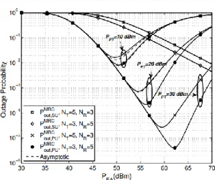
Fig. 3 illustrates the outage probability of the MRC scheme versus 𝑃EA. The outage probability is drawn for
different values of 𝑃PT, and different antennas
configurations. As shown, the outage probability of the MRC scheme for secondary network decreases when
𝑁𝑅 increases. Also, there is an optimum 𝑃EA in which
minimum value of the outage probability is achieved. For the 𝑃EA beneath the optimum value, the outage
probabilities of primary network decrease with the same slop. If the 𝑃EA exceeds its optimum value the
outage probabilities start to increase. The optimum value of 𝑃EA increases as 𝑃PT increases. Additionally,
when 𝑁𝑅 increases, the optimum value of 𝑃EA get
increased.
Fig. 4 shows the outage probability of the primary network versus 𝑃PTfor the proposed TZF, RZF, and
MRC schemes. This figure is depicted for different antennas configuration, when 𝑃EA= 30 dBm. As this
figure represents, the more 𝑁𝑅 and 𝑁𝑇 get, the lower
the outage probability we have. Furthermore, among these schemes, RZF outperforms the two other schemes when 𝑁𝑅 increases. Also, the asymptotic
expressions are depicted, which shows they are well-set with analytical expressions in the high values of
𝑃PT.
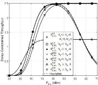
Fig. 5 shows the achieved delay-constrained throughput of the primary network versus the power of energy access point and for two antenna configurations. Moreover, the delay-constrained throughput of the HD counterpart is also included. It is obvious that RZT scheme is superior in terms of delay-constrained throughput in low values of 𝑃EA.
Moreover, the delay-constrained throughput of the primary network with RZF and TZF tends to a constant value at high 𝑃EAvalues due to the outage probability
floor exhibited in Fig. 2. In the MRC scheme it is evident that in power values lower than optimum value, the delay-constrained throughput of MRC scheme follows the same trend as RZF scheme but at power values greater than that optimum value, the
Fig. 5. Delay-constrained throughput of the primary network versus 𝑷𝐄𝐀 for different beamforming design (𝑹𝐜= 5 bits/s/Hz, and 𝑷𝐏𝐓= 10 dBm).
delay-constrained throughput of MRC scheme is decreased due to the degradation of its outage probability (as shown in Fig. 3).
Fig. 6 shows the delay-constrained throughput of the secondary network versus 𝑃EAand for FD and HD
systems. It is clear that by increasing the number of receive antennas from 3 to 5, the delay-constrained throughput of the secondary network is improved. This is due to the fact that by increasing the number of receive antennas the ability of energy harvesting at the STx is improved.
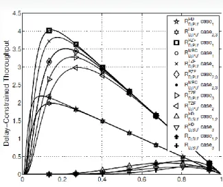
Fig. 7 demonstrates the delay-constrained throughput of the system versus 𝛼 for different antenna configurations. Due to the complexity of the involved outage probability expressions, a closed-form solution of the optimal 𝛼that maximizes (16) and (17) is not possible. Instead, the optimal value of 𝛼 can be numerically evaluated through the Monte Carlo simulations. In Fig. 7, case1 denotes to 𝑁𝑇= 5 and
𝑁𝑅= 5, case2 denotes to 𝑁𝑇 = 3 and 𝑁𝑅 = 5 and
case3 denotes to 𝑁𝑇= 5 and 𝑁𝑅=3. It is clear that
increasing in 𝑁𝑇and 𝑁𝑅 significantly improve the
performance. Moreover, when 𝛼 is increased the delay- constrained throughput of system is increased until 𝛼
achieves its optimum value, then the delay-constrained throughput of the system decreases. This is due to the fact that increasing 𝛼 more that its optimum value causes decrement of transmission time of the information. Furthermore, it could be realized that optimum value of 𝛼 is decreased as 𝑁𝑇 and 𝑁𝑅
increased.
VII. CONCLUSION
In this paper, we have investigated delay-constrained throughput of a wireless-powered FD spectrum-sharing network with NOMA transmissions. We proposed two ZF-based linear beamforming designs at the FD STx to mitigate the SI. We derived the exact and asymptotic expressions for the outage probability of the primary and secondary networks. The results indicated that the ZF-beamforming schemes reach considerable outage performance compared to the
Fig. 6. Delay-constrained throughput of the secondary network versus 𝑷𝐄𝐀 for different beamforming design (𝑹𝒄= 5 bits/s/Hz, and 𝑷𝐏𝐓= 10 dBm).
benchmark beamforming design, MRC/MRT.
Moreover, we perceived that the performance gap between the system can be further increased by deploying more receive antennas at the STx.
APPENDIX A PROOF OF PROPOSITION 1
We start with the characterization of 𝒫2TZF, which can
be expressed as
𝒫2TZF= 𝐏𝐫 (
𝑐0‖𝐡1‖2‖𝐡̃3‖2
𝑐1‖𝐡1‖2‖𝐡̃3‖2+ 𝜎PR2
> 𝜃1,
𝑐1‖𝐡1‖2‖𝐡̃3‖2
𝜎PR2
> 𝜃2),
= 𝐏𝐫(‖𝐡1‖2‖𝐡̃3‖2> 𝜇). (45)
Noticing that ‖𝐡1‖2~𝜒2𝑁𝑅, its pdf is given by
𝑓‖𝐡1‖2(𝑥) = 1 Γ(𝑁𝑅)𝑥
𝑁𝑅−1𝑒−𝑥. On the other hand, according to [6], the ‖𝐡̃3‖2 is also a Chi-squared RV
with 2(𝑁𝑇− 1) d.o.f with cdf given by 𝐹‖𝐡̃3‖2(𝑥) =
1
Γ(𝑁𝑇−1)𝛾(𝑁𝑇− 1, 𝑥). Hence, by using
𝑓‖𝐡1‖2(𝑥) and 𝐹‖𝐡̃3‖2(𝑥), the probability 𝒫2
TZF in (45)
can be expressed as
𝒫2TZF= 1 −Γ(𝑁 1
𝑅)Γ(𝑁𝑇−1)∫ 𝛾(𝑁𝑇− 1,
𝜇 𝑥)𝑥
𝑁𝑅−1𝑒−𝑥 ∞
0
(46) By applying the series expansion of the incomplete Gamma function in [23, Eq.(8.352.1)], (46) can be written as
𝒫2TZ= 1 −
1
Γ(𝑁𝑅)∫ (1 − 𝑒
−𝜇𝑥 ∑ 𝜇𝑚
𝑥𝑚𝑚! 𝑁𝑇−2
𝑚=0
) × 𝑥𝑁𝑅−1𝑒−𝑥𝑑𝑥. ∞
0
(47)
Fig. 7. Delay-constrained throughput of the primary and secondary network versus 𝛼 and for different beamforming design (𝑅𝑐=5 bits/s/Hz, 𝑃PT= 10 dBm, and 𝑃EA= 30 dBm).
Then, after some simple algebraic manipulation and applying [23, Eq.(3.471.9)] we get
𝒫2TZF=Γ(𝑁2
𝑅)∑
𝜇𝑁𝑅+𝑚2
𝑚! 𝐾𝑁𝑅−𝑚(2√𝜇).
𝑁𝑇−2
𝑚=0 (48)
Now, we turn our attention to 𝒫1TZF. According to
𝛾STTZF= 𝑐2‖𝐡2‖2 where ‖𝐡2‖2~𝜒2𝑁𝑅, Therefore, 𝒫1TZF can be readily obtained as
𝒫1TZF=Γ(𝑁1
𝑅)𝛾 (𝑁𝑅,
𝜃2
𝑐2). (49) By plugging (48) and (49) into (18), we arrive at the desired result in (22).
APPENDIX B PROOF OF PROPOSITION 2
By inspecting (23), it is evident that when 𝑁𝑅 is
increased the outage probability of the PRx is decreased. By invoking the series representation of Gamma function in [23, Eq.(8.354.1)] and substituting into 𝑃 (𝑁𝑅,𝜃𝑐2
2), and by omitting the high-order exponent, The asymptotic 𝑃 (𝑁𝑅,𝜃𝑐2
2) can be obtained as
𝑃 (𝑁𝑅,𝜃𝑐2
2) ≈ ΨTZF( 1 𝜌PT)
𝑁𝑅 .
At the end, substituting ΨTZF(𝜌1 PT)
𝑁𝑅
into (18), we achieve the desired result in (23).
APPENDIX C PROOF OF PROPOSITION 3 According to (19) we have
Pout,SUTZF = 𝐏𝐫 (
𝑐3‖𝐡1‖2|𝐡4𝑇𝐰𝑡𝖹𝖥| 2
𝑐4‖𝐡1‖2|𝐡4𝑇𝐰𝑡𝖹𝖥| 2
+ 𝜎S𝖱2
< 𝜃2),
= 𝐏𝐫 (‖𝐡1‖2|𝐡4𝑇𝐰𝑡𝖹𝖥| 2
< 𝜉) (50)
Given that |𝐡4𝑇𝐰𝑡𝖹𝖥| 2
follows exponential distribution[26], for 𝜃2<𝑐𝑐3
4 we have
Pout,SUTZF = ∫ Γ(𝑁1
𝑅)𝛾 (𝑁𝑅,
𝜉 𝑥) 𝑒
−𝑥𝑑𝑥. ∞
0 (51)
Now, by utilizing [23, Eq. (6.453)], we obtain the desired result in (25).
APPENDIX D PROOF OF PROPOSITION 6
By using the same steps to proof of Proposition 1, 𝒫2MRC can be expressed as
𝒫2MRC= 2 Γ(𝑁𝑅)∑
𝜇𝑁𝑅+𝑚2
𝑚! 𝑁𝑇−1
𝑚=0 𝐾𝑁𝑅−𝑚(2√𝜇). (52)
According to (31),‖𝐡2‖2~𝜒2𝑁𝑅, ‖𝐡1‖2~𝜒2𝑁𝑅 and
|𝐰𝑟MRC†𝐇SI𝐰𝑡MRT| 2
follows exponential
distribution [27]. Therefore, 𝒫1MRC can be written as
𝒫1MRC= 𝐏𝐫 ( 𝑐5‖𝐡2‖
2
𝑐6‖𝐡1‖2|𝐰𝑟MRC†𝐇SI𝐰𝑡MRT| 2
+𝜎ST2 < 𝜃2),
=Γ2(𝑁1
𝑅)∫ ∫ 𝑥
𝑁𝑅−1𝑦𝑁𝑅−1 ∞
0 ∞
0 𝑒
−𝑐5𝑥−𝜃2𝜎ST2
𝜃2𝜎SI2 𝑐6𝑦𝑒−𝑥
× 𝑒−𝑦𝑑𝑥𝑑𝑦. (53)
By applying [23, Eq. (3.471.9)] we have
𝒫1MRC=
1 Γ2(𝑁
𝑅)∫ 2 (
𝑐5𝑥 − 𝜃2𝜎ST2
𝜃2𝜎SI2𝜃6 ) 𝑁𝑅
2 ∞
0
× 𝐾𝑁𝑅(2√
𝑐5𝑥−𝜃2𝜎𝖲𝖳2
𝜃2𝜎SI2𝑐6 ) 𝑥
𝑁𝑅−1𝑒−𝑥𝑑𝑥. (54)
Finally, by substituting (52) and (54) into (18), we achieve the desired result in (32).
APPENDIX E PROOF OF COROLLARY 1
By ignoring the noise term of the 𝛾STMRC, 𝒫̃1MRC can be
upper bounded as
𝒫̃1MRC<
1 Γ2(𝑁
𝑅)∫ 2 (
𝑐5𝑥
𝜃2𝜎SI2𝑐6) 𝑁𝑅
2 ∞
0
× 𝐾𝑁𝑅(2√𝜃𝑐5𝑥
2𝜎SI2𝑐6) 𝑥
𝑁𝑅−1𝑒−𝑥𝑑𝑥. (55)
Now by applying the integral identity [23, Eq. (6.643.3)], the integral (55) can be solved as
𝒫̃1MRC<
Γ(2𝑁𝑅)
Γ(𝑁𝑅) (
𝑐5
𝜃2𝜎SI2𝑐6) 𝑁𝑅−1
2
𝑒
𝑐5 2𝜃2𝜎SI2𝑐6
× 𝑊1
2−32𝑁𝑅,𝑁𝑅2 (
𝑐5
𝜃2𝜎SI2𝑐6). (56)
Finally, substituting (52) and (56) into (18) yields the desired result.
REFERENCES
[1] A. Sabharwal, P. Schniter, D. Guo, D. W. Bliss, S. Rangarajan, and R. Wichman, “In-band full-duplex wireless: Challenges and opportunities,” IEEE J. Sel. Areas Commun., vol. 32, pp. 1637–1652, Sep. 2014.J. Clerk Maxwell, A Treatise on Electricity and Magnetism, 3rd ed., vol. 2. Oxford: Clarendon, 1892, pp.68–73.
[2] M. Duarte, “Full-duplex wireless: Design, implementation and characterization,” Ph.D. dissertation, Dept. Elect. and Computer Eng., Rice University, Houston, TX, 2012. [3] L. Laughlin, M. A. Beach, K. A. Morris, and J. L. Haine,
“Optimum single antenna full duplex using hybrid junctions,” IEEE J. Sel. Areas Commun., vol. 32, pp. 1653–1661, Sep. 2014.
[4] T. Riihonen, S. Werner, and R. Wichman, “Mitigation of loopback self-interference in full-duplex MIMO relays,” IEEE Trans. Signal Process., vol. 59, pp. 5983–5993, Dec. 2011. [5] H. A. Suraweera, I. Krikidis, G. Zheng, C. Yuen, and P. J.
Smith, “Low-complexity end-to-end performance optimization in MIMO full-duplex relay systems,” IEEE Trans. Wireless Commun., vol. 13, no. 2, pp. 913–927, Jan. 2014.
[6] M. Mohammadi, B. K. Chalise, H. A. Suraweera, C. Zhong, G. Zheng, and I. Krikidis, “Throughput analysis and optimization of wireless-powered multiple antenna full-duplex relay systems,” IEEE Trans. Commun., vol. 64, no. 4, pp. 1769– 1785, Apr. 2016.
[7] S. Haykin, “Cognitive radio: Brain-empowered wireless communications,” IEEE J. Sel. Areas Commun., vol. 23, no. 2, pp. 201–220, Feb. 2005.
[8] R. Manna, R. H. Y. Louie, Y. Li, and B. Vucetic, “Cooperative spectrum sharing in cognitive radio networks with multiple antennas,” IEEE Trans. Signal Process., vol. 59, pp. 5509– 5522, Nov 2011.
[9] H. Kim, S. Lim, H. Wang, and D. Hong, “Optimal power allocation and outage analysis for cognitive full duplex relay systems,” IEEE Trans. Wireless Commun., vol. 11, pp. 3754– 3765, Oct. 2012.
[10] M. Amjad, F. Akhtar, M. H. Rehmani, M. Reisslein, and T. Umer, “Full-duplex communication in cognitive radio networks: A survey,” IEEE Commun. Surveys Tutorials, vol. PP, no. 99, pp. 1–1, 2017.
[11] Y. Saito, Y. Kishiyama, A. Benjebbour, T. Nakamura, A. Li, and K. Higuchi, “Non-orthogonal multiple access (NOMA) for cellular future radio access,” in Proc. IEEE 77th Veh. Technol. Conf. (VTC’13), Dresden, Germany, June 2013, pp. 1–5. [12] Z. Ding, X. Lei, G. K. Karagiannidis, R. Schober, J. Yuan,
andV. K. Bhargava, “A survey on non-orthogonal multiple accessfor 5G networks: Research challenges and future trends,” IEEE J. Sel. Areas Commun., vol. 35, no. 10, pp. 2181–2195, Oct. 2017.
[13] M. Mohammadi,X. Shi, B. K. Chalise, Z. Ding, H. A. Suraweera, C. Zhong, and J. S. Thompson, ``Full-duplex non-orthogonal multiple access for next generation wireless systems", IEEE Communications Magazine, vol. 57, pp. 110-116, May 2019.
[14] Z. Mobini, M. Mohammadi, H. A. Suraweera, and Z. Ding, “Full-duplex multi-antenna relay assisted cooperative nonorthogonal multiple access,” in Proc. IEEE Global Commun. Conf. (GLOBECOM 17) ´ , Singapore, Dec 2017, pp. 1–7.
[15] L. Lv, J. Chen, and Q. Ni, “Cooperative non-orthogonal multiple access in cognitive radio,” IEEE Commun. Lett., vol. 20, pp. 2059–2062, Oct. 2016.
[16] Y. Liu, Z. Ding, M. Elkashlan, and J. Yuan, “Nonorthogonal multiple access in large-scale underlay cognitive radio networks,” IEEE Trans. Veh. Technol., vol. 65, pp. 10 152–10 157, Dec. 2016.
[17] L. Lv, J. Chen, Q. Ni, and Z. Ding, “Design of cooperative non-orthogonal multicast cognitive multiple access for 5G systems: User scheduling and performance analysis,” IEEE Trans. Commun., vol. 65, pp. 2641–2656, June 2017.
[18] M. Mohammadi, B. K. Chalise, A. Hakimi, H. A. Suraweera, and Z. Ding, “Joint beamforming design and power allocation for full-duplex NOMA cognitive relay systems,” in Proc.
IEEE Global Commun. Conf. (GLOBECOM’17) , Singapore, Dec 2017, pp. 1-7.
[19] S. Buzzi, C. I, T. E. Klein, H. V. Poor, C. Yang, and A. Zappone, “A survey of energy-efficient techniques for 5G networks and challenges ahead,” IEEE J. Sel. Areas Commun., vol. 34, pp. 697–709, Apr. 2016.
[20] S. Bi, Y. Zeng, and R. Zhang, “Wireless powered communication networks: An overview,” IEEE Wireless Commun. Mag., vol. 23, no. 2, pp. 10–18, Apr. 2016. [21] Y. Alsaba, C. Y. Leow, and S. K. A. Rahim, “Full-duplex
cooperative non-orthogonal multiple access with beamforming and energy harvesting,” IEEE Access, vol. 6, pp. 19 726–19 738, 2018.
[22] P. Deng, B. Wang, W. Wu, and T. Guo, “Transmitter design in MISO-NOMA system with wireless-power supply,” IEEE Commun. Lett., vol. 22, pp. 844–847, Apr. 2018.
[23] I. S. Gradshteyn and I. M. Ryzhik, Table of Integrals, Series and Products, 7th ed. Academic Press, 2007.
[24] M. Mohammadi, B. K. Chalise, A. Hakimi, Z. Mobini, H. A. Suraweera, and Z. Ding, “Beamforming design and power allocation for full-duplex non-orthogonal multiple access cognitive relaying,” IEEE Trans. Commun., vol. 66, pp. 5952– 5965, Dec. 2018.
[25] Wireless Power Solutions-Powercast Corp. [Online]. Available: http://www.powercastco.com.
[26] M. Mohammadi, H. A. Suraweera, and C. Tellambura, “Uplink/downlink rate analysis and impact of power allocation for full-duplex cloud-RANs,” IEEE Trans. Wireless Commun.,vol. 17, pp. 5774 – 5788, Sept. 2018.
[27] A. Hakimi, M. Mohammadi, and Z. Mobini, “Outage probability of wireless powered multiantenna cooperative spectrum sharing networks with full-duplex and NOMA transmissions,” in 9th International Symposium on Telecommunications (IST), IEEE, pp. 127-132, Dec. 2018.
Azar Hakimi received the B.Sc. and the M.Sc. degrees in Electrical Engineering from the Shahrekord University, Iran, in 2015 and 2018, respectively. Her research interests are in the areas of Cognitive Radio Cooperative Communication Systems, Wireless Information and Power Transfer, and Non-Orthogonal Multiple Access Communications.
Mohammadali Mohammadi (S’09, M’15) received the B.S. degree in Electrical Engineering from the Isfahan University of Technology, Isfahan, Iran, in 2005, and the M.Sc. and Ph.D. degrees in the same Electrical Engineering from K. N. Toosi University of Technology, Tehran, Iran in 2007 and 2012, respectively. From November 2010 to November 2011, he was a visiting researcher in the Research School of Engineering, the Australian National University, Australia, working on Cooperative Networks. He is currently an Associate Professor in the Faculty of Engineering, Shahrekord University, Iran. His main research interests include Cooperative Communications, Energy Harvesting and Green Communications, Full-Duplex Communications and Stochastic Geometry.
Zahra Mobini (S’09, M’15) received the B.Sc. degree in Electrical Engineering from Isfahan University of Technology, Isfahan, Iran, in 2006, and the M.Sc. and Ph.D. degrees, both in Electrical Engineering, from the M. A. University of Technology and K. N. Toosi University of Technology, Tehran, Iran, respectively. From November 2010 to November 2011, she was a Visiting Researcher at the Research School of Engineering, Australian National University, Canberra, ACT, Australia. She is currently an Assistant Professor with the Faculty of Engineering, Shahrekord University, Shahrekord, Iran. Her research interests include Wireless Communication Systems, Cooperative Networks, and Network Coding.