UDC 625.122
V. D. PETRENKO
1, O. L. TIUTKIN
2, I. O. SVIATKO
3*1Dep. «Bridges and Tunnels», Dnipropetrovsk National University of Railway Transport named after Academician V. Lazaryan,
Lazaryan St., 2, Dnipro, Ukraine, 49010, tel. +38 (056) 373 15 79, e-mail [email protected], ORCID 0000-0002-5902-6155 2Dep. «Bridges and Tunnels», Dnipropetrovsk National University of Railway Transport named after Academician V. Lazaryan,
Lazaryan St., 2, Dnipro, Ukraine, 49010, tel. +38 (056) 373 15 79, e-mail [email protected], ORCID 0000-0003-4921-4758 3*Dep. «Bridges and Tunnels», Dnipropetrovsk National University of Railway Transport named after Academician V. Lazaryan,
Lazaryan St. 2, Dnipro, Ukraine, 49010, tel. +38 (056) 373 15 79, e-mail [email protected], ORCID 0000-0002-7099-2637
ESTIMATION OF SUBGRADE STRENGTHENING INFLUENCE
USING SOILCEMENT ELEMENTS
Purpose. The aim of this work is to identify dependencies and options to strengthen the roadbed and a weak
base by grouting piles. Analysis of software package SCAD to assess the effect of the selected option of strengthen-ing the construction of spatial subgrade models. Methodology. In this paper the method of calculation of the soil
mass in the software package SCAD is considered, which is a universal accounting system of finite-element analysis of structures and is focused on solving problems of designing buildings and structures rather complex structure. The finite element method is among the most modern and effective methods for the calculation of structures for various purposes. In the simulation, we get a complete picture of the stress-strain state of the study area, as well as the value of the limit load, rainfall, and so on. The spatial model based on the finite element volume, to better address the real characteristics of the soil mass, meets all the geometric characteristics of size and natural subgrade and the top struc-ture the path that has been adopted in Ukraine. Findings. It was found that the most effective option to strengthen
the roadbed, when applying grouting piles at the base of the subgrade and body, is to strengthen the five piles. At the same time there is even strengthen the soil mass at the level of 25 … 30% of the entire depth. However, even with the strengthening of the only two piles at the base of the effect of the strengthening of 14.1%. Established equation is linear and describes the decrease in strain. Taking into account the results of the research can be concluded that the consolidation is proportional to the depth with any number of piles. The dependence of the strain on the number of piles adheres to a polynomial function. Strengthening the bases of the subgrade and body depth also occurs in proportion with any number of piles. Originality. Design scheme generation algorithm for the calculation of the subgrade on a weak basis by finite element method was determined. The selection of strength characteristics of soils and the design parameters for use during the numerical simulation was completed. Load process simulation of the system by rolling stock was grounded. Practical value. Analysis of stress-strain state of «weak base-subgrade» al-lows you to see the basic laws work the soil and take the necessary measures to enhance the cross-section profile of jet-grouting elements.
Keywords: subgrade; weak base; soil cement; stress-deformed state
Introduction
The main priority of rail transport is to provide of goods and passengers safety.
All facilities should be designed so as to corre-spond to its purpose, to be stable and reliable. De-sign of bases is a complex task that takes into ac-count engineering and geological conditions as well as the design and performance properties of the structure.
Under the influence of the load from rolling stock and own weight of permanent way the soils deformed, and its deformation is greater than the greater tension in the soil. Deformation of soils bring to setting of structure. The tensions should
not exceed the limits in order to be secured condi-tions of stability and safety of permanent way [1, 4, 10].
Breach of the foundation stability displace in the form of displacement of natural soil mass, bringing to injuries or disturbance of the roadbed, such as soil slips, dips and more.
Experience of designing and performance of track structure showed that over time should take some measures to improve the characteristics of the soil mass to be able to the follow normal per-formance of the roadbed. [5, 3, 13]
strengthening of transport facilities, in particular at strengthening the roadbed as well as weak bases.
Purpose
The aim of this work is to identify dependen-cies and parameters of subgrade strengthening and weak base using soilcement piles. Analyses of us-ing of SCAD software system came for assessus-ing of impact choose variant of strengthening for struc-ture of roadbed spatial models.
Methodology
The most of appropriate and promising method for assessment of roadbed stress-strain state is modeling the spatial models using finite element method. In this paper considers the method of cal-culation of soil mass by software complex SCAD, which is a universal calculation system of finite-element analysis of structures and orientate on so-lution the tasks of designing buildings and con-structions rather complex structure. The method of finite elements it goes to the most modern and ef-fective methods for the calculation of structures for various purposes. During the simulation we get a complete picture of the stress-strain state of the study area and the limit value loading, sedimenta-tion, etc.
The spatial model based on volumetric finite elements to better take into account the real
charac-teristics of the soil mass meets all the geometric characteristics and natural size of subgrade and permanent way, which was adopted in Ukraine.
Deformation characteristics, those taken in the model correspond to the values which have been obtained in the study of subgrade soil [6, 7, 14].
At the time modeling applied so restrictions (boundary conditions):
− on the model bottom impose a ban on movements in the direction of the three axis – X, Y, Z;
− lateral facets of base have a ban on move-ments over the axis X and Y;
− diametrical sides of model – a ban of move-ments over axis Y (plane deformations condition). [8, 9, 12]
Top of model and also embankment slopes have no restrictions – free from boundary condi-tions.
The thickness of the computational model (on the axis Y) adopted 1.15 m, which corresponds to the width of two standard sleepers and two dis-tances between sleepers with its epures 1740 piec-es/km. The model is symmetrical on thickness rela-tively of axis X. Inclination of the railway slope make 1: 1.5. General view of the roadbed plan is shown in Figure 1.
Fig. 2. The calculation model in program complex SCAD
All calculations performed by the multifrontal method of expansion of rigidity matrix with auto-matic optimization of the tape width, as this meth-od is the most progressive when working with ma-trixes, which used to program complex SCAD [2, 11, 12, 15].
After the complete linear calculation values of deformations relatively axis Z and axis X were obtained. Precision of matrix expansion is 1x10¹².
General view of model in program complex SCAD shown in Figure 2.
In this paper have considered the following var-iants of strengthening: placement of soilcement piles with a diameter of 0.5 m only in the base of roadbed and in base and through the body of road-bed. Adopted by number of piles are two, three and five, respectively, for each variant.
In all cases soilcement piles were disposed symmetrically about the axis of the track.
During the calculations of strengthening varia-tions the length of piles at the base is 3 m long and the length of piles in the base and in the body of embankment – 9 meters. The distance from the lower end of the pile to the bottom of the calcula-tion model is 1.0 m.
Findings
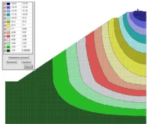
After carry out of the control calculation unfor-tified subgrade have been received the maximum deformations along the axis Z (Figure 3), that form 14.21 mm, and along the axis X (Figure 4) – 2.45 mm. At the level of the transition from the body of the embankment to the base subgrade is a slight curvature in view of change point with characteris-tic modification of direction deformation behavior.
It should also be noted that in the area of crossing from base to embankment remain about 50% of total deformations, which is 7 mm.
According to the results obtained with the strengthening by two soilcement piles only in the base, the overall deformation on the axis Z in the level of rail head formed 13.4 mm (Figure 5.), that is 5.7% less than the control calculation. Deforma-tions of model in which additional piles were in the body of the embankment totaled 12.20 mm, that is 14,1% less deformations of unfortified models.
By the level of foot sleeper the deformations on the axis Z have been reduced in the case of strengthening of base on 4.0% and in the case of strengthening the base with the body of the em-bankment – on 14.0%.
Fig. 3. The calculation without strengthening by soilcement piles. Deformation on the axis Z
Fig. 5. Deformation on the axis Z. The calculation of two piles in base
In addition, the model the characteristic chang-es of izofields deformations on the placchang-es of pilchang-es existing. It should be noted that in the area of crossing between weak base and embankment total deformation decreased on average by 16%.
In strengthening of roadbed by three soilcement piles, so be observed decrease of deformation on the axis Z. Thus the effect of the pile using only in base and in the base and body of embankment sig-nificantly different. In the first case, reducing of deformations by the level of rail head happened on 8.2%, while in the second case – almost three times more – 20.6%.
However, in the plane of crossing between the base and the body of embankment exist several another situation. On the contrary, the strengthen-ing only base reduce the deformations was about 27.3%, whereas the strengthening through the body of embankments exists of decrease by only 23.0%.
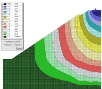
The calculation results in the strengthening by five soilcement piles testify about the following. The maximum deformation in the level of rail head totaled 12.62 mm and 10.57 mm at strengthening only bases and base with body of embankment re-spectively, representing a decrease of 11.2% and 25.6%. However, on the boundary of crossing from the base to the body of the embankments the effect from strengthening is the same reaching 29.1 … 29.5% with comparison the control calculation. Also on the present boundary become more pro-nounced the change of isolines (Figure 6).
Fig. 6. Deformation on the axis Z. The calculation the five piles at the base
and body of embankments
Originality and practical value
The algorithm of forming design scheme for calculating of the embankment on the weak base by the finite element method has been determined. The selection of soil strength characteristics and the calculation parameters for use in numerical modeling has been done. The modeling of loading system process by rolling stock has been grounded. Analysis of stress-strain state of the system «weak base – roadbed» permit to see the basic reg-ularities of soil work and use of embankment cross-section profile strengthening by soilcement elements.
The method of subgrade on weak base model-ing that reflects with their work under loadmodel-ing by own weight and rolling stock has been proposed.
Conclusions
Figure 7. Graph of deformations Z (mm) in strengthening only base
of embankment depending on number piles in base
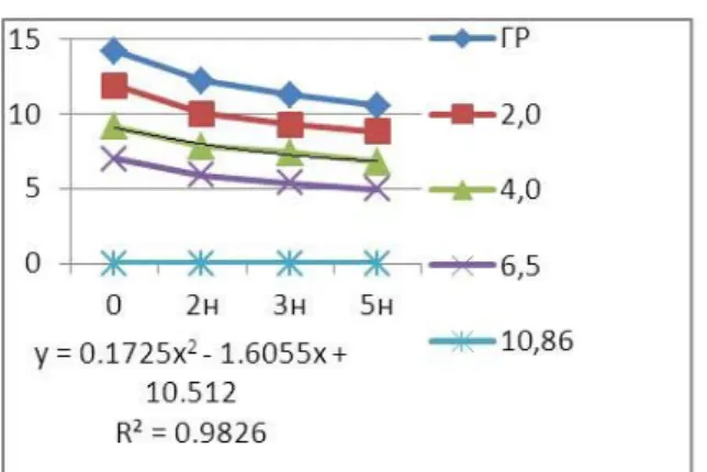
Fig. 8. . Graph of deformations Z (mm) in strengthening of base and of the body of embankment depending on number piles in base
Take into consideration these graphs possible to draw a conclusion that the strengthening is propor-tional to the depth at any number of piles. The de-pendence of the deformations from number of piles follows polynomial functions and describes by the equation y = 0,0875h2 – 0,9585h + 9.9675. The
strengthening of base and of embankment body at the depth also happens proportionately for any number of piles. The dependence of the deforma-tions on the number of piles follows polynomial functions and describes by the equation y = 0,1725h2 – 1,6055h + 10.512.
LIST OF REFERENCE LINKS
1. Державна цільова програма реформування залізничного транспорту на 2010–2019 роки [Elrctronic resource] : законопроектУкраїнивід 16 груд. 2009 р. № 1390. – Available at: http://zakon2.rada.gov.ua/laws/show/1390. – Title from the screen. – Accessed : 13.09.2016.
2. ДБНВ.2.1-10-2009. Зміна№ 1. Основитафун -даменти споруд. Основні положення проекту -вання. – На заміну СНИП 2.02.03-85 ; чинні з 2011–07–01. – Киів : Мінрегіонбуд України, 2011. – 126 c.
3. Інструкція з улаштування та утримання колії залізниць України : ЦП-0138./ Е. І. Даніленко, В. О. Яковлев, А. М. Орловський [та ін.]. – Киів : НКТБ колійного гос-ва Укрзалізниці, 2006. – 56 с.
4. Кожушко, В. П. Основиіфундаменти : підруч. длявузів : в 2-хч. – Харків : ХНАДУ, 2002. – Ч. 2. – 492 с.
5. Линченко, Ю. П. Моделированиесвайногоос -нования здания с применением интегральных элементов / Ю. П. Линченко, А. Е. Шуст // Стр -воитехногенная безопасность : сб. науч. тр. / Нац. акад. природоохран. и курортного стр-ва. – Симферополь, 2010. – Вып. 33–34. – С. 176–182.
6. Литовченко, П. А. Численное моделирование взаимодействия буроинъекционной сваи с ло -кальнымзакреплениемвгрунтеиокружающе -гоеегрунтовогомассива / П. А. Литовченко // Стр-во, материаловедение, машиностроение : сб. науч. тр. / Приднепров. гос. акад. стр-ва иархитектуры. – Днепропетровск, 2013. – Вып. 69. – С. 322–327.
7. Новые возможности системы ГРУНТ для оп -ределения параметров жесткости грунтового и свайного оснований / Д. А. Городецкий, В. П. Максименко, Д. В. Медведенко, Е. Б. Стрелец-Стрелецкий // Стр-во, материа -ловедение, машиностроение : сб. науч. тр. / Приднепров. гос. акад. стр-ваиархитектуры. – 2013. – Вып. 69. – С. 155–160.
8. Петренко, В. Д. Порівняльний аналіз методів укріплення земляного полотна / В. Д. Петрен -ко, І. О. Святко, Д. О. Ямпольський// Стр-во, материаловедение, машиностроение : сб. науч. тр. / Приднепров. гос. акад. стр-ваиархитекту -ры. – Днепропетровск, 2013. – Вып. 69. – С. 369–373.
9. Петренко, В. Д. Порівняльнийаналізрозрахун -кових моделей залізничного земляного по -лотна / В. Д. Петренко, Д. О. Ямпольський, І. О. Святко // Науката прогрестранспорту. – 2013. – № 4 (46). – Р. 56–62. doi: 10.15802/stp-2013/16619.
10. Правила розрахунків залізничної колії на міцність і стійкість : ЦП-0117 : затв. наказом Укрзалізниці від 13.12.2004 р. № 960-ЦЗ. – Киів : ЦПУЗ, 2004. – 69 c.
Л. А. Строкова. – Томск : Изд-воТомск. поли -техн. ун-та, 2010. – 143 с.
12. Тютькин, А. Л. Сравнительный анализ конеч -но-элементных моделей свайного фунда- мента при взаимодействии с основанием / А. Л. Тютькин, А. В. Гулак // Вісн. Дніпропетр. нац. ун-ту залізн. трансп. ім. акад. В. Лаза -ряна. – Дніпропетровськ, 2010. – Вип. 32. – С. 122–126.
13. Horvát F. Evaluation of railway track geometry stabilisation effect of geogrid layers under ballast on the basis of laboratory multi-level shear box
tests / F. Horvát, Sz. Fisher, Z. Major // Acta Technica Jaurinensis. – 2013. – № 2. – P. 21–44. 14. Hogue, S. Building Simulation Tools for
Retrofit-ting Residential Structures / S. Hogue // Energy Engineering. – 2012. – Vol. 109. – Iss. 3. – P. 53–74.
15. Ziaie-Moay, R. Effective parameters on modulus of subgrade reaction in clayey soils / R. Ziaie-Moay, M. Janbaz // J. of Applied Sciences. – 2009. – Vol. 9. – Iss. 22. – P. 4006–4012. doi: 10.3923/jas.2009.4006.4012.
В
.
Д
.
ПЕТРЕНКО
1,
О
.
Л
.
ТЮТЬКІН
2,
І
.
О
.
СВЯТКО
3*1Каф. «Моститатунелі», Дніпропетровськийнаціональнийуніверситетзалізничноготранспортуіменіакадеміка
В. Лазаряна, вул. Лазаряна, 2, Дніпро, Україна, 49010, тел. +38 (056) 373 15 79, ел. пошта [email protected],
ORCID 0000-0002-5902-6155
2Каф. «Моститатунелі», Дніпропетровськийнаціональнийуніверситетзалізничноготранспортуіменіакадеміка
В. Лазаряна, вул. Лазаряна, 2, Дніпро, Україна, 49010, тел. +38 (056) 373 15 79, ел. пошта [email protected],
ORCID 0000-0003-4921-4758
3*Каф. «Моститатунелі», Дніпропетровськийнаціональнийуніверситетзалізничноготранспортуіменіакадеміка
В. Лазаряна, вул. Лазаряна, 2, Дніпро, Україна, 49010, тел. +38 (056) 373 15 79, ел. пошта [email protected],
ORCID 0000-0002-7099-2637
ОЦІНКА
ВПЛИВУ
УКРІПЛЕННЯ
ЗЕМЛЯНОГО
ПОЛОТНА
ҐРУНТОЦЕМЕНТНИМИ
ЕЛЕМЕНТАМИ
Мета. Вроботіпередбачаєтьсявиявитизалежностітапараметриукріпленняземляногополотнаіслабкої основи за допомогою ґрунтоцементних паль. Також потрібно зробити аналіз використання програмного комплексу SCAD дляоцінкивпливуобраноговаріантуукріпленняприпобудовіпросторовоїмоделіземля -ного полотна. Методика. В даній роботі розглядається методика розрахунку ґрунтового масиву упрограмномукомплексі SCAD, якийєуніверсальноюрозрахунковоюсистемоюкінцево-елементногоана -лізу конструкцій та орієнтований на вирішення завдань проектування будівель і споруд досить складної структури. Методскінченнихелементіввідноситьсядонайбільшсучаснихіефективнихметодівдлярозра -хунку споруд різного призначення. Під час моделювання отримуємо повну картину напружено -деформованого стану досліджуваної області, а також значення граничного навантаження, осідання тощо. Просторовамодельнаосновіоб’ємнихкінцевихелементів, длякращоговрахуванняреальниххарактеристик ґрунтовогомасиву, відповідаєвсімгеометричнимхарактеристикамінатурнимрозмірамземляногополотна таверхньої будови колії, якаприйнятана територіїУкраїни. Результати. Встановлено, щонайефективні -шим варіантом укріплення земляного полотна, при влаштуванні ґрунтоцементних паль восновійтілінасипу, єукріпленняп’ятьмапалями. Прицьомуспостерігаєтьсярівномірнеукріпленняґрун -тового масиву на рівні 25…30 % по всій глибині. Проте, навіть із укріпленням лише двома палями воснові, ефектвідукріпленнястановить 14,1 %. Встановленорівняння, якемаєлінійнийхарактеріописує зменшення деформацій. Приймаючи до уваги результатидосліджень, можназробити висновки, що укріп -ленняпоглибинівідбуваєтьсяпропорційноприбудь-якійкількостіпаль. Залежністьдеформаційвідкілько -стіпальдотримуєтьсяполіноміальної функції. Укріпленняосновиі тіланасипупоглибині такожвідбува -єтьсяпропорційноприбудь-якій кількостіпаль. Науковановизна. Авторамивизначено алгоритм форму -ваннярозрахунковоїсхемидля розрахункунасипунаслабкійосновіметодомскінченнихелементів. Вико -нано підбір міцнісних характеристик ґрунтів та розрахункових параметрів для застосування під час чисельного моделювання. Обґрунтовано моделювання процесу навантаження системи рухомим складом.
Практичназначимість. Аналізнапружено-деформованогостанусистеми «слабкаоснова-землянеполотно» дозволяєпобачитиосновнізакономірностіроботиґрунтуівжитинеобхіднізаходидляпідсиленняпопереч -ногопрофілюґрунтоцементнимиелементами.
В
.
Д
.
ПЕТРЕНКО
1,
А
.
Л
.
ТЮТЬКИН
2,
И
.
А
.
СВЯТКО
3*1Каф. «Мостыитоннели», Днепропетровскийнациональныйуниверситетжелезнодорожноготранспортаимени
академикаВ. Лазаряна, ул. Лазаряна, 2, Днипро, Украина, 49010, тел. +38 (056) 373 15 79,
эл. почта [email protected], ORCID 0000-0002-5902-6155
2Каф. «Мостыитоннели», Днепропетровскийнациональныйуниверситетжелезнодорожноготранспортаимени
академикаВ. Лазаряна, ул. Лазаряна, 2, Днипро, Украина, 49010, тел. +38 (056) 373 15 79,
эл. почта [email protected], ORCID 0000-0003-4921-4758
3*Каф. «Мостыитоннели», Днепропетровскийнациональныйуниверситетжелезнодорожноготранспортаимени
академикаВ. Лазаряна, ул. Лазаряна, 2, Днипро, Украина, 49010, тел. +38 (056) 373 15 79,
эл. почта [email protected], ORCID 0000-0002-7099-2637
ОЦЕНКА
ВЛИЯНИЯ
УКРЕПЛЕНИЯ
ЗЕМЛЯНОГО
ПОЛОТНА
ГРУНТОЦЕМЕНТНЫМИ
ЭЛЕМЕНТАМИ
Цель. В работе предполагается выявить зависимости и параметры укрепления земляного полотна ислабого основания спомощью грунтоцементных свай. Также необходимо сделать анализ программного комплекса SCAD дляоценкивлияния выбранноговариантаукрепления припостроениипространственной моделиземляногополотна. Методика. Вданнойработерассматриваетсяметодикарасчетагрунтовогомас -сива в программном комплексе SCAD, который является универсальной расчетной системой конечно -элементногоанализаконструкций иориентированнарешениезадачпроектированиязданийисооружений достаточно сложной структуры. Метод конечных элементов относится к наиболее современным и эффективным методам для расчета сооружений различного назначения. При моделировании получаем полную картину напряженно-деформированного состояния исследуемой области, а также значение пре -дельнойнагрузки, осадкиипрочее. Пространственнаямодельнаосновеобъемныхконечныхэлементов, для лучшегоучетареальныххарактеристикгрунтовогомассива, соответствуетвсемгеометрическимхарактери -стикаминатурнымразмерамземляногополотнаиверхнегостроенияпути, которыепринятынатерритории Украины. Результаты. Установлено, чтонаиболееэффективнымвариантомукрепленияземляногополотна, приустройствегрунтоцементныхсвайвоснованииителенасыпи, являетсяукреплениепятьюсваями. При этомнаблюдаетсяравномерноеукреплениегрунтовогомассиванауровне 25…30 % повсейглубине. Одна -ко, дажесукреплением толькодвумясваямив основе, эффект отукрепления составляет 14,1 %. Найдено уравнение, котороеимеетлинейныйхарактериописываетуменьшениедеформаций. Принимаявовнимание результатыисследований, можносделатьвыводы, чтоукреплениепоглубинепроисходитпропорционально прилюбомколичествесвай. Зависимостьдеформацийотколичествасвайпридерживаетсяполиномиальной функции. Укрепление основы и тела насыпи по глубине также происходит пропорционально при любом количестве свай. Научная новизна. Авторами определен алгоритм формирования расчетной схемы для расчетанасыпинаслабомоснованииметодомконечныхэлементов. Выполненподборпрочностныххарак -теристикгрунтовирасчетныхпараметровдляприменениячисленногомоделирования. Обоснованомодели -рованиепроцессанагрузки системыподвижным составом. Практическая значимость. Анализнапряжен -но-деформированного состояниясистемы «слабоеоснование-земляноеполотно» позволяетувидетьоснов -ныезакономерностиработыгрунтаипринятьнеобходимыемерыдляусиленияпоперечногопрофилягрун -тоцементнымиэлементами.
Ключевые слова: земляное полотно; слабое основание; грунтоцементные элементы; напряженно
-деформированноесостояние
REFERENCES
1. Derzhavna tsilova prohrama reformuvannia zaliznychnoho transportu na 2010–2019 roky: zakonoproekt Ukrainy vid 16 hrudnia 2009 r. № 1390 (The state target program of reforming the railway transport in 2010-2019 years). Available at: http://zakon2.rada.gov.ua/laws/show/1390 (Accessed 13 September 2016).
2. DBN V.2.1-10-2009. Zmina № 1. Osnovy ta fundamenty sporud. Osnovni polozhennia proektuvannia [State Construction Standart V.2.1-10-2009. Change No. 1. Bases and foundations of buildings. General of the de-sign.]. Kyiv, Minrehionbud Ukrainy Publ., 2011. 126 p.
4. Kozhushko V.P. Osnovy i fundamenty [Bases and foundations]. Kharkiv, KhNAHU Publ., 2002. Part 2. 492 p. 5. Linchenko Yu.P., Shust A.Ye. Modelirovaniye svaynogo osnovaniya zdaniya s primeneniyem integralnykh
elementov [Pile foundation simulation of the building with the integrated elements usage]. Sbornik nauchnykh trudov «Stroitelstvo i tekhnogennaya bezopasnost» [Proc. «Construction and technogenic safety»], 2010, issue 33-34, pp. 176-182.
6. Litovchenko P.A. Chislennoye modelirovaniye vzaimodeystviya buroinektsionnoy svai s lokalnym zakre-pleniyem v grunte i okruzhayushchego yeye gruntovogo massiva [Numerical modeling the interaction of in-clined pile with local fixing in the ground and its surrounding soil mass]. Sbornik nauchnykh trudov «Stroitel-stvo, materialovedeniye, mashinostroeniye» [Proc. «Construction, materials science, mechanical engineer-ing»], 2013, issue 69, pp. 322-327.
7. Gorodetskiy D.A., Maksimenko V.P., Medvedenko D.V., Strelets-Streletskiy Ye.B. Novyye vozmozhnosti sistemy GRUNT dlya opredeleniya parametrov zhestkosti gruntovogo i svaynogo osnovaniy [New opportuni-ties of system GRUNT for determining stiffness parameters of subgrades and pile foundations]. Sbornik nauchnykh trudov «Stroitelstvo, materialovedeniye, mashinostroeniye» [Proc. «Construction, materials sci-ence, mechanical engineering»], 2013, issue 69, pp. 155-160.
8. Petrenko V.D., Sviatko I.O., Yampolskyi D.O. Porivnialnyi analiz metodiv ukriplennia zemlianoho polotna [Comparative analysis of methods for subgrade strengthening]. Sbornik nauchnykh trudov «Stroitelstvo, mate-rialovedeniye, mashinostroeniye» [Proc. «Construction, materials science, mechanical engineering»], 2013, is-sue 69, pp. 369-373.
9. Petrenko V.D., Yampolskyi D.O., Sviatko I.O. Porivnialnyi analiz rozrakhunkovykh modelei zaliznychnoho zemlianoho polotna [Comparative analysis of calculation models of railway subgrade]. Nauka ta prohres transport – Science and Transport Progress, 2013, no. 4 (46), pp. 56-62. doi: 10.15802/stp2013/16619. 10. Pravyla rozrakhunkiv zaliznychnoi kolii na mitsnist i stiikist: TsP-0117. Nakaz Ukrzaliznytsi vid 13.12.2004 r.
№ 960-TsZ [Calculations of railway track for strength and stability. Ukrzaliznytsia Order No. 960-TsZ]. Kyiv, TsP UZ Publ., 2004. 69 p.
11. Strokova L.A. Primeneniye metoda konechnykh elementov v mekhanike gruntov [Application of finite element method in soil mechanics]. Tomsk, Tomskiy politekhnicheskiy universitet Publ., 2010. 143 p.
12. Tyutkin A.L., Gulak A.V. Sravnitelnyy analiz konechno-elementnykh modeley svaynogo fundamenta pri vzaimodeystvii s osnovaniyem [Comparative analysis of finite element models of pile foundation in coopera-tion with base]. Visnyk Dnipropetrovskoho natsionalnoho universytetu zaliznychnoho transportu imeni akad-emika V. Lazariana [Bulletin of Dnipropetrovsk National University of Railway Transport named after Aca-demician V. Lazaryan], 2010, issue 32, pp. 122-126.
13. Horvát F., Fisher Sz., Major Z. Evaluation of railway track geometry stabilisation effect of geogrid layers un-der ballast on the basis of laboratory multi-level shear box tests. Acta Technica Jaurinensis, 2013, no. 2, pp. 21-44.
14. Hogue S. Building Simulation Tools for Retrofitting Residential Structures. Energy Engineering, 2012, vol. 109, issue 3, pp. 53-74.
15. Ziaie-Moay R., Janbaz M. Effective parameters on modulus of subgrade reaction in clayey soils. Journal of Applied Sciences, 2009, vol. 9, issue 22, pp. 4006-4012. doi: 10.3923/jas.2009.4006.4012.
Prof. N. B. Kurhan Dr. Sc. (Tech.) (Ukraine); Prof. A. V. Slodyankin Dr. Sc. (Tech.) (Ukraine) recommended this article to be published