R E S E A R C H
Open Access
Gain, noise and intermodulation
in a nonlinear superconducting resonator
Erik A Tholén
1, Adem Ergül
2, David Schaeffer
2and David B Haviland
2**Correspondence: [email protected] 2Nanostructure Physics, Royal
Institute of Technology (KTH), Stockholm, Sweden Full list of author information is available at the end of the article
Abstract
A superconducting microwave resonator is modified with several weak links to make it nonlinear and operated as a phase-insensitive microwave amplifier. Signal gain is demonstrated by intermodulation with a strong pump. The gain is sharply frequency dependent, and we demonstrate phase dependence by examining correlations between the signal and one idler which is a 3rd order intermodulation product of the pump and signal tones. A calibration procedure is described which is based on measurement of both thermal and quantum noise, revealing that the following HEMT amplifier adds noise at 15 times the quantum limit. When operated as a
phase-insensitive amplifier the nonlinear resonator added noise at 2.5 times the quantum limit. Significant power is found at intermodulation products beyond 3rd order, which may be responsible for the inability to reach the quantum limit.
PACS Codes: 74.78.-w; 42.65.Yj; 85.25.Cp
Keywords: intermodulation; parametric amplifier; quantum noise
1 Introduction
Minimal dissipation and a designable nonlinearity are the important attributes of su-perconductors which are enabling the development of quantum electrodynamic circuits. These attributes are manifested in distributed microwave structures with eigenmodes that are suitably modified by tunnel junctions or weak links to make them nonlinear. Such circuits find use in: single photon detection [], generating [] and routing [] single mi-crowave photons, detecting the state of individual quantum bits [], and even as the qubit itself []. An important general purpose application is microwave signal amplification at the quantum limit of added noise []. Here we present measurements of gain, noise and intermodulation in a superconducting nonlinear resonator operated as phase-insensitive signal amplifier. Good agreement is achieved between measurement and a theory that includes one parameter describing a cubic nonlinear term. However, we observe strong response at high-order intermodulation frequencies which is not included in the theory. We believe that power lost to high-order intermodulation is responsible for the inability of the amplifier to squeeze noise at the quantum limit.
2 Amplification at the quantum limit
A fundamental theorem of signal amplification states that any narrow-band linear am-plifier providing significant power gain to a signal of arbitrary phase applied to its input, must add noise at its output, where the added noise power per unit bandwidth, or added
noise energy, is at least one half the zero-point fluctuation energy at the signal frequency [].
EaddedN ≥
hfs ()
It is however possible to create amplifiers that are not subject to this minimum added noise theorem. The phase-sensitive parametric amplifier operates with a pump that periodically modulates a parameter of a linear system. Signals which drive the system at half the pump frequency are amplified when they are in phase with the pump, whereas quadrature signals are de-amplified. This squeezing of a signal results in overall power gain, where power is transferred from the pump to the signal, and it is in principle a reversible process that can be performed with no added noise. Squeezing at the quantum limit produces a squeezed vacuum state, as recently demonstrated [].
The utility of a phase-sensitive amplifier is however limited to applications where one has prior knowledge of the phase of the input signal, which is often not the case. A phase-insensitive amplifier is more useful as a general purpose measurement tool and there is growing interest in phase-insensitive amplification with noise performance at the quan-tum limit [–]. In its simplest form, phase-insensitive amplification is realized when a nonlinear system mixes two drive tones, a strong pump tone at frequencyfpand a much
weaker signal tone at frequencyfs, to generate an idler tone at fi=fp–fs. This mixing
can provide gain for arbitrary phase of the signal and squeezing becomes apparent in the correlation between the externally applied signal tone and the internally generated idler tone, which are both locked to the same pump. This type of squeezing is also in principle a reversible amplification of the signal which can be undone if both the signal and idler are applied to another identical nonlinear resonator with an appropriately phase-shifted pump. The reversibility of the process implies that it can be performed without added noise.
The idler in this most simple case is generated by intermodulation of the applied sig-nal and pump tones and it can be understood as resulting from a quadratic nonlinearity. Consider a standing wave in a transmission line with a current-dependent inductanceL(i). The fluxΦ(t), which is defined in terms of the potential at one end of the line,V=ddtΦ, obeys a nonlinear equation of motion.
(πf)
dΦ dt +
πfQ
dΦ
dt +Φ+
N
n=
gnΦn=Φdrive(t) ()
The coefficientsgndescribe an arbitrary conservative nonlinearity of degreeNandfand Qare the characteristic frequency and quality factor of the linear resonator. To first order in the nonlinear perturbation, a drive consisting of two tones will generate a correction to the linear response of the resonator containing terms of the form,
∼gn
Aseiπfst+Apeiπfpt
n
()
Generally, to any order in a perturbative expansion (so long as it converges) and for a nonlinearity of arbitrary degree, response to a two-tone drive is generated only at frequen-cies which are intermodulation products of the drive tones,
fIMP=nsfs+npfp ()
where ns and np are integers. The order of the intermodulation product is given by
|ns|+|np|. In nonlinear optics second-order intermodulation is referred to as three-wave
mixing, describing the interaction of three electromagnetic waves travelling through a medium having aχor quadratic nonlinearity. This type of nonlinearity occurs in
crys-tals which lack a point of inversion symmetry []. For superconducting resonators the Josephson junction or weak link nonlinearity has a current-flux relation which is an odd function,i(+Φ) = –i(–Φ), leading to a nonlinear oscillator equation with only odd pow-ers ofΦ,i.e.Eq. () withgeven= . Therefore second order intermodulation is typically
absent in passive Josephson devices. However, three-wave mixing or second order inter-modulation can be realized in actively driven, or parametric Josephson devices, which are non-reciprocal in nature [].
In the nonlinear resonator studied here we realized phase-insensitive amplification by third-order intermodulation of the signal and pump ( wave mixing) where the idler is at frequencyfi= fp–fs. This intermodulation product can be generated by a nonlinear
oscillator with agcoefficient only, known as the Duffing oscillator or Kerr nonlinearity.
A detailed theory of the cavity parametric amplifier perturbed by a Kerr nonlineary has been worked out by Yurke and Buks [] and extended to the two port system measured here []. When comparing our measurements to this theory we could produce excel-lent agreement between the theory and experiment by adjusting the parameters of the theory [, ]. Here we extend this analysis to measurements of noise. We also present measurements of higher order intermodulation products forming a frequency comb of response near resonance. These products are typically not looked for in experiments on parametric amplification, but we found significant power at these frequencies, especially when measuring de-amplification of a signal tone. We speculate that this higher order intermodulation is responsible for not being able to efficiently squeeze with our amplifier.
3 Experimental details and calibration
The nonlinear resonator is a thin-film Nb coplanar waveguide (CPW) fabricated with a photo lithography process by Star Cryoelectronics []. Input and output ports were coupled to the resonator by interdigitating the center line of the resonator with tapered CPW feed lines. We attempted to make asymmetric coupling with smaller interdigitating length at the input, but we found that both ports had nearly the same coupling, indicating the coupling is primarily due to fringing fields. The distributed resonator has a series of eigenmodes when its length is close to an integer multiples of the electromagnetic half-wavelengthLnλ
. Here we present measurements of the response in the vicinity of the
fundamental eigenmode (n= ) withf= . GHz. A nonlinear inductance was
Figure 1 Schematic diagram of the microwave setup used to realize phase-insensitive amplification and homodyne detection.
A schematic diagram of the measurement setup is shown in Figure . The sample is mounted in a dilution refrigerator with base temperature mK. The pump and signal tones are combined at room temperature and applied via a coax transmission line to the resonator input. Two stages of attenuation at low temperatures are used on the input side to bring the thermal radiation at the input into thermal equilibrium at the base temper-ature of the cryostat. Signals emerging from the output are sent through a circulator to a cryogenic pre-amplifier mounted at the K stage of the cryostat. The circulator, with the third terminal connected to a termination acts as an isolator, protecting the res-onator from the back-action noise of the cryogenic preamplifier. The signal at the output of the preamplifier is amplified again by a room-temperature microwave amplifier followed by another isolator, and then an IQ mixer for homodyne detection using a phase-shifted copy of the pump signal as the local oscillator. In this arrangement, both the signal and idler tones will be coherently down-converted to the same frequencyΔf =fs–fp. A
vari-able delay shifts the phase of the pump signal, allowing one to probe the phase dependence of the signal and idler gains, that is the squeezing.
The cryogenic HEMT amplifier is the dominant source of noise in our setup. We tested amplifiers from Miteq, Amplitech, and Low Noise Factory [], the later being far superior to the others with dB of gain in the band – GHz with a DC power consumption of only mW. The back-action noise from at input stage of the HEMT amplifier is isolated from the resonator and brought in to thermal equilibrium at the base temperature of the cryostat by the termination at one port of the cold circulator. If the termination on the circulator is in equilibrium with the cryostat’s calibrated restive thermometer, the noise emitted from this source can used to calibrate the measurement system. Noise from this source is measured in a very narrow frequency band (effective bandwidth . kHz) centred at the frequencyfc. The measurement band does not overlap with the
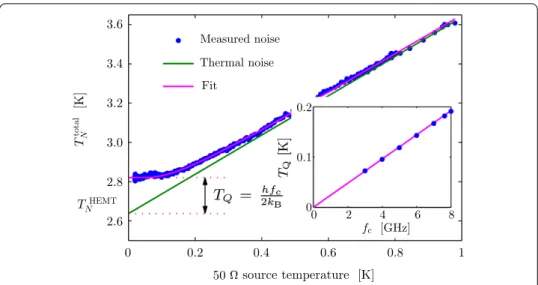
Figure 2 Microwave noise power is calibrated in a narrow band centered at the frequency fc= 7.62 GHz, by varying the temperature of the 50termination on the cold circulator.
A one-parameter fit to Eq. (5), adjusting only the overall gain factor, allows for determination of the HEMT amplifiers noise temperatureTHEMT
N = 2.62 K and observation of the quantum noiseTQ= 0.18 K. The data
points in the inset are the quantum noise at different center frequencies in the band of the HEMT amplifier, and the straight line is the expected behaviorTQ=2hfckB.
this source, plus the added noise of the HEMT amplifier.
EtotalN (T) =EHEMTN + hfccoth
hfc
kBT
, ()
where we have used the quantum expression for the fluctuations from the source. This simple expression assumes that all inputs and outputs are matched to , which is the case.
We measured the noise as a function of temperature and fit the theory Eq. () to the measured data as shown in Figure , where the noise is expressed as an effective tem-peratureTN = EkNB. The least-squared fit was obtained by adjusting only one parameter,
the overall scale factor on the vertical axis. This scale factor contains the gains and at-tenuations from all of the various components in our measurement chain, which would not be easy to calibrate independently. At high temperatureskBT>hfcthe data approach
the Johnson-Nyquist thermal noise from the source, which the fit determines as the straight green line in Figure . TheT= intersection of this line with the noise axis gives the added noise of the HEMT amplifier, TNHEMT= . K. The difference between the amplifiers added noise and the measured noise extrapolated toT= , is the quantum noise,TQ. We performed this measurement at several center frequenciesfcto verify that
the quantum noise determined by this fitting procedure behaved as expectedTQ=hfkcB (see
inset of Figure ).
Thus it is possible to use noise to calibrate the microwave measurement chain against the cryostat’s calibrated restive thermometer. We are also able to directly measure the quantum noise with the HEMT amplifier, which adds onlyTNHEMTTQto the total
Figure 3 Frequency response of the parametric amplifier with the pump turned off and the pump turned on.The pump frequency isfp= 7.6069 GHz which is 1.55 MHz below the resonant frequency of the
resonator in the linear regime. The pump power is –83.8 dBm at the input of the sample box. The red line is a fit to the theory made by adjusting the strength of the Kerr nonlinearity.
when we observed that problems with the source not being in thermal equilibrium with the cryostats thermometer were clearly evident in the poor quality of the fit to Eq. () to the data []. This calibration method has been use for Planck spectroscopy of thermal microwave states [].
4 Measurements and analysis
Signal amplification by the nonlinear resonator is demonstrated in Figure which shows a measurement of the signal transmission when the pump power and frequency are fixed atPp= –. dBm andfp= . GHz, very close to bifurcation point of the nonlinear
resonator. In this measurement the signal source and mixer are replaced by the output and input ports of a network analyser respectively, and the signal power is fixed toPs=
–. dBm while its frequency is swept. The measurement was calibrated so that dB corresponds to unity transmission between the input and output connectors of the board on which the chip is mounted. The transmission curve at this signal power (green data in Figure ) in the absence of the pump is also shown in Figure which is well described by the Lorentzian lineshape of a driven, damped harmonic oscillator with resonant frequency
f= . GHz and widthγ= kHz (Q=πγf = ,).
When the pump is turned on we observe gain in a rather narrow band which is sharply peaked at zero detuning between the pump and signal, with a maximum gain of dB (blue data points in Figure ). Using the values offandQdetermined from the
trans-mission curve in the linear regime, and the value of a cubic nonlinear term determined by fitting transmission curves at many different signal powers, when the resonator is in the nonlinear regime (data not shown) we could calculate the theoretically expected frequency dependent gain [, ] (red line in Figure ). Good correspondence with the measured sig-nal gain is seen over many times the resonator bandwidth. We found that including the nonlinear damping parameter in the theory did not improve the quality of the fit.
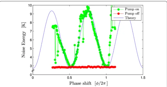
Figure 4 Phase dependence of the noise power in a 30 kHz bandwidth, with the pump on (green) and pump off (red).The solid line is the theoretical expectation taking in to account the frequency dependence of the gain. Instabilities in the amplifier cause jumps in the measurements.
of the input and output ports. Here we report noise and intermodulation measurements which were made in a subsequent cool-down of the sample. The thermal cycling of the sample caused a slight shift of the bifurcation point and for the following measurements the working point of the pump wasfp= . GHz andPp= – dBm.
With the signal turned off we measured only the noise in a kHz bandwidth as the phase shifter is varied. Note that here we are measuring noise close to resonance, so the noise measured is inside the cavity and it is effected by the noise entering from both the input and output ports. In Figure we see that noise at the output of the mixer is clearly phase-dependent, verifying that intermodulation with the pump is causing a correlation of the frequency components of a random signal that are equally spaced from pump,
fp±Δf. We see that when the phase shifter is adjusted for minimum noise (maximum
de-amplification) we recover the independently measured value of the HEMT amplifiers added noise . K. This value is the same as the noise measured when the pump is off (red data in Figure ). When the phase shifter is adjusted for maximum gain we find that the nonlinear cavity amplifier adds and additional . K of noise to the total noise power. Taking in to account the frequency dependence and phase dependence of the gain, we can estimate the phase dependence of the total measured noise as,
TNtotal(φ) =TNHEMT+
kHz
G(φ,f)TQ+TNNLO df ()
whereTNLO
N is the temperature of the added noise of the nonlinear oscillator. This
theoret-ical curve is shown in Figure withTNNLO= . K. The jumps observed in the measured data are due to instabilities of the nonlinear oscillator which is biased close to the bifur-cation point.
In another measurement we applied a signal with fixed frequency withΔf =fs–fp=
Figure 5 Power spectrum measured at the output of the mixer when a signal is applied at Δf=fs–fp= 10 kHz.Measurements are shown when the pump is on (blue) and when the pump is off
(green), for two cases: (a) the phase shifter is tuned for maximum amplification, and (b) the phase shifter is tuned for maximum de-amplification. The measurement reveals both signal and noise gain, and the additional peaks at integer multiples ofΔfare due to higher-order intermodulation products of the signal and pump.
, power spectra were averaged. To avoid Fourier leakage between different compo-nents in the spectrum, we synchronized the microwave generators and the sampling clock on the ADC, and we chose both pump and signal frequencies to be integer multiples of the sampling frequency.
Figure shows the averaged power spectra when the phase shifter is adjusted for max-imum amplification (Figure (a)) and maxmax-imum de-amplification (Figure (b)). Measure-ments with the pump both on and off are shown in each figure. For these measureMeasure-ments, the power is normalized so that dB corresponds to the pump off noise level. Comparing the height of the signal peak at kHz for the pump on and pump off case, we find dB of amplification and dB of de-amplification of the signal tone. Also evident is a large number of peaks at integer multiples ofΔf, corresponding to higher order intermodula-tion products of the signal and pump. Between the peaks we can see the noise level, which reveals the frequency dependence of the amplifiers gain. In Figure (a) we find that the signal-to-noise ratio (SNR) at kHz improves by a factor of . when the pump is on. Since the pump off noise is measured to be that of the HEMT amplifier, we can determine the added noise of the nonlinear oscillator to beTNLO
N =TNHEMT/. = . K, consistent
with the previous measurement.
5 Discussion and conclusions
The peaks in Figure (a) and Figure (b) at integer multiples ofΔf correspond to odd or-der intermodulation products (e.g.fp±fs,fp±fs, fp±fs, fp±fsetc.). It is difficult to
pin-point the source of these higher order intermodulation products: They may be gen-erated in the nonlinear resonator as a result of expansion coefficientsgnwith oddn>
in Eq. (), or from the gterm in higher order perturbation theory. Nonlinearity of the
signal, and we speculate that they also inhibiting the measurement of noise squeezing at the quantum limit.
One way in which one might control this loss of power to higher order intermodula-tion is to filter the higher-order IMPs by designing a system where the linear response is negligible at undesirable intermodulation products. Another strategy would be to design a drive consisting of a frequency comb with the amplitude and phase of each component appropriately tuned to cancel the undesired response. In fact, these IMPs can be measured in a phase-coherent way and used for accurate reconstruction of the actual nonlinearity []. Development is under way to make system which will allow for driving and measur-ing response with arbitrary, phase-coherent frequency combs [].
In this paper we measured intermodulation response near one resonance and analyzed the data within the context of a basic theory of a nonlinear system with only two degrees of freedom,i.e.one oscillator equation describing one eigenmode of the transmission line []. A distributed system actually has many standing waves and the ideal transmission line has resonances at integer multiples of the fundamental resonant frequency,nf. Deviations
from this ideal behaviour occur due to finite coupling to input and output ports, as well as the frequency shift due to the linear part of the weak-link inductance. Because we observe IMPs of th order near the fundamental resonance, one really should examine the first eigenmodes to determine if they are excited by harmonics or intermodulation products of the signal and pump. If so, we expect additional loss of signal power, diminishing the performance of the amplifier. Since the frequencies of these higher eigenmodes are out of the band of our HEMT amplifier, we are unable to measure their response and typically they are not measured in other experiments with cavity parametric amplifiers. Note how-ever, that we do not expect excitation near even multiples offbecausegeven= for the
nonlinear oscillator considered here. The excitation of higher eigenmodes by harmonics and intermodulation might be avoided by designing lumped-element resonators with a more complicated mode structure [], but it is a potential problem in designs which use separate transmission line resonators to store the signal and idler []. Filtering response at higher harmonics and higher order intermodulation products is generally more diffi-cult to achieve when the quality factor of the eigenmodes is decreased to achieve larger bandwidth of the amplifier.
In conclusion, we have realized phase-insensitive amplification of a microwave signal at . GHz using a nonlinear superconducting resonator pumped close to bifurcation. A peak gain of dB was realized, but it was strongly frequency-dependent in a narrow band with a dB bandwidth of only MHz. We used a calibrated resistive thermometer to calibrate the microwave noise measurement and with the following HEMT amplifier we measured the standard quantum limit on noise,TQ=hfkB, where the noise temperature of the HEMT
amplifier was onlyTHEMT
N = . K, corresponding to TQ. When operated as an amplifier
the nonlinear resonator achieved dB of signal gain in a kHz bandwidth with noise temperatureTNLO
N = . K, corresponding to .TQ. We were not able to demonstrate
squeezing of vacuum fluctuations by examining correlations between the signal and rd order idler. Correlations involving higher order idlers were not examined.
Competing interests
Authors’ contributions
EAT and DBH conceived the experiment. EAT and AE performed the experiments and analysis. All authors took part in preparation of the manuscript.
Author details
1Intermodulation Products AB, Solna, Sweden.2Nanostructure Physics, Royal Institute of Technology (KTH), Stockholm,
Sweden.
Acknowledgements
We acknowledge stimulating discussions with Steve Girvin, Jack Lidmar, Hans Hansson, Per Delisng and Chris Wilson. This work was funded by the EU project SCOPE, FET-Open grant number 218783, the Swedish Research Council VR, the Kunt and Allice Wallenberg Foundation and the Olle Engkvist Foundation.
Received: 31 August 2013 Accepted: 6 January 2014 Published: 7 March 2014
References
1. Gao J, Vissers MR, Sandberg MO, da Silva FCS, Nam SW, Pappas DP, Wisbey DS, Langman EC, Meeker SR, Mazin BA, Leduc HG, Zmuidzinas J, Irwin KD:Appl Phys Lett2012,101(14):142602.
2. Houck AA, Schuster DI, Gambetta JM, Schreier JA, Johnson BR, Chow JM, Frunzio L, Majer J, Devoret MH, Girvin SM, Schoelkopf RJ:Nature2007,449(7160):328.
3. Hoi IC, Wilson CM, Johansson G, Palomaki T, Peropadre B, Delsing P:Phys Rev Lett2011,107:073601. 4. Boissonneault M, Doherty AC, Ong FR, Bertet P, Vion D, Esteve D, Blais A:Phys Rev A2012,85:022305.
5. Paik H, Schuster DI, Bishop LS, Kirchmair G, Catelani G, Sears AP, Johnson BR, Reagor MJ, Frunzio L, Glazman LI, Girvin SM, Devoret MH, Schoelkopf RJ:Phys Rev Lett2011,107:240501.
6. Clerk AA, Devoret MH, Girvin SM, Marquardt F, Schoelkopf RJ:Rev Mod Phys2010,82:1155. 7. Caves CM:Phys Rev D1982,26(8):1817.
8. Mallet F, Castellanos-Beltran MA, Ku HS, Glancy S, Knill E, Irwin KD, Hilton GC, Vale LR, Lehnert KW:Phys Rev Lett2011, 106:220502.
9. Yurke B, Buks E:J Lightwave Technol2006,24(12):5054.
10. Tholén EA, Ergül A, Doherty EM, Weber FM, Grégis F, Haviland DB:Appl Phys Lett2007,90(25):253509. 11. Abdo B, Suchoi O, Segev E, Shtempluck O, Blencowe M, Buks E:Europhys Lett2009,85(6):68001.
12. Bergeal N, Schackert F, Metcalfe M, Vijay R, Manucharyan VE, Frunzio L, Prober DE, Schoelkopf RJ, Girvin SM, Devoret MH:Nature2010,465(7294):64.
13. Abdo B, Kamal A, Devoret M:Phys Rev B2013,87:014508.
14. Yaakobi O, Friedland L, Macklin C, Siddiqi I:Phys Rev B2013,87:144301. 15. Wustmann W, Shumeiko V:Phys Rev B2013,87:184501.
16. Franken PA, Hill AE, Peters CW, Weinreich G:Phys Rev Lett1961,7:118. 17. Kamal A, Clarke J, Devoret MH:Phys Rev B2012,86:144510.
18. Stannigel K:Parametric amplification in superconducting resonators.Master’s thesis. KTH; 2007. 19. Tholén EA, Ergül A, Stannigel K, Hutter C, Haviland DB:Phys Scr2009,T137:014019.
20. Tholén E:Intermodulation in microresonators: for microwave amplification and nanoscale surface analysis.Ph.D. thesis. KTH, Nanostructure Physics; 2009. http://kth.diva-portal.org/smash/get/diva2:277877/FULLTEXT01.pdf. 21. STAR Cryoelectronics, Santa Fe, New Mexico. http://www.starcryo.com/.
22. Low Noise Factory, Göteborg, Sweden. http://www.lownoisefactory.com/.
23. Castellanos-Beltran MA, Irwin KD, Hilton GC, Vale LR, Lehnert KW:Nat Phys2008,4(12):929.
24. Mariantoni M, Menzel EP, Deppe F, Araque Caballero MA, Baust A, Niemczyk T, Hoffmann E, Solano E, Marx A, Gross R: Phys Rev Lett2010,105:133601.
25. Platz D, Forchheimer D, Tholén EA, Haviland DB:Nanotechnology2012,23(26):265705.
26. Tholén EA, Platz D, Forchheimer D, Tholén MO, Hutter C, Haviland DB:Rev Sci Instrum2011,82:026109. arXiv:1008.2722v1.
27. Levenson-Falk EM, Vijay R, Siddiqi I:Appl Phys Lett2011,98:123115.
doi:10.1140/epjqt5