Volume 31 (2010)
Proceedings of the
Second International Workshop on
Visual Formalisms for Patterns
(VFfP 2010)
Enforcement of Patterns by Constraint-Aware Model Transformations
Yngve Lamo, Adrian Rutle and Florian Mantz
12 pages
Guest Editors: Paolo Bottoni, Esther Guerra, Juan de Lara
Managing Editors: Tiziana Margaria, Julia Padberg, Gabriele Taentzer
Enforcement of Patterns by Constraint-Aware Model
Transformations
Yngve Lamo1, Adrian Rutle1 and Florian Mantz1
1yla,aru,[email protected],http://www.hib.no∗
Department of Computer Engineering Bergen University College, Norway
Abstract: Patterns are descriptions and solutions for recurring problems in software
design and implementation. In this paper, some ideas towards a formal approach to the specification of patterns in model-driven engineering (MDE) is presented. The approach is based on the Diagram Predicate Framework which provides a formal ap-proach to (meta)modelling, model transformation and model management in MDE. In particular, patterns are defined as diagrammatic specifications and constraint-aware model transformations are adapted to enforce patterns. Moreover, running examples are used to illustrate the facade design pattern in structural models.
Keywords: Pattern, constraint-awareness, model transformation, model refactoring,
Diagram Predicate Framework
1
Introduction and motivation
Since the beginning of computer science, developing high-quality software at low cost has been a continuous vision. This has boosted several shifts of programming paradigms, e.g. machine code to compilers and imperative to object-oriented programming. In every shift of paradigm, raising the abstraction level of programming languages and technologies has proved to be beneficial to increase productivity. One of the latest steps in this direction has lead to the usage of models and modelling languages in software development processes.
Initially, models were adopted in software development processes for sketching the architec-tural design or documenting an existing implementation. In the latest trend in software engineer-ing, however, models are regarded as first-class entities of the development process. These mod-els are used to automatically generate (parts of) software systems by means of model-to-model and model-to-code transformations. In the literature, this trend is referred to as model-driven engineering (MDE).
Software development projects have traditionally been built following the waterfall approach, a sequential process consisting of requirements specification, design, implementation, testing, deployment and maintenance phases. Often a new project was started from scratch by designing the domain model, architecture model, code etc. without any clear methodology or systematic use of earlier experiences. In this context, natural questions which arise are: What is software quality? What is best practice in software engineering? What is a good design? What is an appropriate architecture for a certain kind of software systems? What is a good piece of software?
To address the problem with software quality, in the late eighties Kent Beck and Ward Cun-ningham began experimenting with the idea of applying patterns to software engineering [BC87]. Moreover, the seminal book [GHJV94] on design patterns published in 1994 by the so-called “Gang of Four” had a great influence on software development practise. Design patterns are usually used as a solution strategy for a common problem, e.g. facade, decorator, singleton, etc, and often describe a solution for a part of a bigger system. Although design patterns have been applied in software development for a long time, formalisation of the concept of patterns is still an open research topic [BGL09]. Moreover, patterns are usually explained in a semi formal or informal language.
In MDE the process of developing software is performed by use of (semi-)automatic develop-ment steps in form of model transformations. Hence, to fully benefit from patterns in MDE the patterns should be expressed formally, facilitating model transformations and automatic software development steps. In MDE, patterns are used in different phases and for different means during the software development process:
• means for communication, e.g. among developers and domain experts
• guideline for design; i.e. as a specification for software design and software behaviour
• tool for conformance check; i.e. to check whether a model follows a given pattern or not
• guideline for design change; i.e. if the design does not follow the desired pattern, the pattern may be forced by use of model transformations and refactoring.
To be practically useful, patterns in MDE should meet some criteria, e.g they should be formal, abstract, conceptually clear, intuitive, adaptable and reusable. To enhance usability of patterns, it is natural to employ a diagrammatic approach, but still demanding a precise (formal) meaning of the diagrammatic models. The proposed approach of this paper is based on the Diagram Pre-dicate Framework (DPF) [Rut10,RRLW10,RRLW09], which is a generalisation and adaptation of the categorical sketch formalism [BW95], where user-defined diagrammatic predicate signa-tures represent the constructs of modelling languages in a more direct way. In particular, DPF is an extension of the Generalised Sketches [Mak97] formalism [Dis03]. DPF aims to combine mathematical rigour – which is necessary to enable automatic reasoning – with diagrammatic modelling.
In this paper, we use DPF to formalise concepts related to patterns in MDE. We will define these concepts in general in the sense that they may be applied for design patterns or other kinds of patterns such as input and output patterns of model transformation rules.
Usually patterns describe the structure of an architecture or a problem solution for a (sub)system. In MDE a pattern could be represented by a structural model. To ensure the desired behavior of the system the pattern should also have the possibility to describe some of the constraints that the system needs to fulfil. Hence a proper formalisation of patterns should also have the possibility to express actual constraints.
2
Diagram Predicate Framework
DPF is a generic graph-based specification framework that tends to adapt first-order logic and categorical logic to software engineering needs. DPF is generic in the sense that it supports any kind of graph structures (see [DW08] for the general case). However, the variant of DPF which we employ in this paper is based on directed multi-graphs.
Before introducing the formal foundation of DPF, the terminology adopted in this paper is clarified in the following. The word “model” has different meanings in different contexts. In software engineering, model denotes “an abstraction of a (real or language-based) system allow-ing predictions or inferences to be made” [Küh06]. Models in software engineering are typically diagrammatic. The word “diagram” has also different meanings in different contexts. In software engineering, diagram denotes a structure which is based on graphs; i.e. a collection of nodes to-gether with a collection of arrows between nodes. Since graph-based structures can be visualised in a natural way, “visual” and “diagrammatic” modelling are often treated as synonyms. In this paper, visualisation and diagrammatic syntax are clearly distinguished. That is, the proposed approach focuses on precise syntax and semantics of diagrammatic models independent of their visualisation.
In DPF, models are represented by (diagrammatic) specifications. A specificationS= (S, CS:
Σ)consists of an underlying graphS together with a set of atomic constraintsCS [RRLW09,
Rut10]. The graph represents the structure of the model while atomic constraints add restrictions to this structure. Atomic constraints are formulated by predicates from (diagrammatic
predic-ate) signatures. A signature Σ = (PΣ, αΣ)consists of a collection of predicates, each having a name, a shape graph, a visualisation and a semantic interpretation [RRLW09, Rut10]. The formal definitions are as follows:
Definition 1 (Signature) A signatureΣ = (PΣ, αΣ)consists of a collection of predicate sym-bolsPΣ with a mappingαΣ that assigns a graph to each predicate symbolp∈PΣ. αΣ(p) is called the arity of the predicate symbolp.
Definition 2 (Atomic Constraint) Given a signatureΣ = (PΣ, αΣ), an atomic constraint(p, δ) on a graphSis given by a predicate symbolpand a graph homomorphismδ:αΣ(p)→S1.
Definition 3 (Specification) Given a signatureΣ = (PΣ, αΣ), a specificationS= (S, CS: Σ)
is given by a graphSand a setCSof constraints(p, δ)onSwithp∈PΣ.
Definition 4 (Specification Morphism) Given two specifications S= (S, CS: Σ) and S′ = (S′, CS′: Σ), a specification morphism φ:S→S′ is a graph homomorphismφ:S→S′ such that(p, δ)∈CSimplies(p, δ;φ)∈CS′
, illustrated by the following diagram:
αΣ(p) δ
δ;φ
=
S φ S′
Nodes and arrows of a specification have to be interpreted in a way which is appropriate for
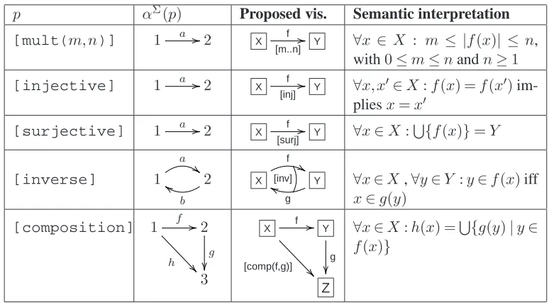
Table 1: A sample signatureΣ = (PΣ, αΣ)
p αΣ(p) Proposed vis. Semantic interpretation
[mult(m, n)] 1 a 2 X f
[m..n] Y ∀x ∈ X : m ≤ |f(x)| ≤ n,
with0≤m≤nandn≥1
[injective] 1 a 2 X f
[inj] Y ∀x, x
′∈X:f(x) =f(x′)
im-pliesx=x′
[surjective] 1 a 2 X f
[surj] Y ∀x∈X:
S
{f(x)}=Y
[inverse] 1
a
2
b
X f
Y
g
[inv] ∀x∈X,∀y∈Y :y∈f(x)iff
x∈g(y)
[composition] 1 f
h
2
g
3
X f
[comp(f,g)] Y
g
Z
∀x∈X:h(x) =S{g(y)|y∈
f(x)}
the corresponding modelling environment [RRLW09]. In object-oriented structural modelling, each object may be related to a set of other objects. Hence, it is appropriate to interpret nodes as
sets and arrowsX−→f Y as multi-valued functionsf:X→℘(Y). The powerset℘(Y)ofY is the set of all subsets ofY; i.e.℘(Y) ={A|A⊆Y}. Moreover, the composition of two multi-valued functionsf:X→℘(Y), g:Y →℘(Z)is defined by(f;g)(x) :=S{g(y)|y∈f(x)}.
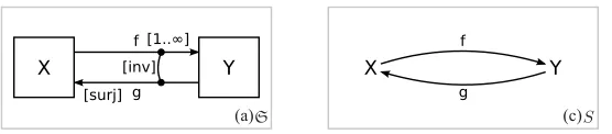
Example 1 (Sample signature and specification) Table1shows a small sample signatureΣ = (PΣ, αΣ). Fig.1a shows a sample diagrammatic specification(S, CS:Σ)and Fig.1b shows the
underlying graphSofS; i.e. the graph ofSwithout any constraints. InS, the nodesXandY
are interpreted as setsXandY, and the arrowsfandgare interpreted as multi-valued functions f :X→℘(Y)and g:Y →℘(X), respectively. Moreover, the functiongis surjective; this is forced by the constraint([surjective], δ1)on the arrowg. Similarly, the functionfis total; this is forced by the constraint([mult(1,∞)], δ3)on the arrowf. Finally, the functionsf and gare inverse of each other; i.e.∀x∈Xand∀y∈Y :x∈g(y)iffy∈f(x). This is forced by the constraint([inverse], δ2)onfandg. The graph homomorphismsδ1,δ2andδ3are defined as follows:
δ1(1) =Y, δ1(2) =X, δ1(a) =g
δ2(1) =X, δ2(2) =Y, δ2(a) =f, δ2(b) =g δ3(1) =X, δ3(2) =Y, δ3(a) =f
In DPF, we use specifications to represent models at any level of a metamodelling hierarchy. Moreover, we distinguish between two types of relations between models and metamodel: typed
by and conforms to. A specification Sn at level n is typed by a specification Sn+1 at level n+ 1if there exists a typing morphismιSn:S
S (c) f
g
X Y
(a)S [inv]
f
g X
[1..∞]
[surj]
Y
Figure 1: A sample specification (a)S= (S, CS: Σ)and (b) its underlying graphS
specifications. This corresponds to the relation between a model and its metamodel in the graph-based formalisation of the metamodelling hierarchy. In contrast, a specification Sn at level nis said to conform to a specification Sn+1 at level n+ 1 if there exists a typing morphism ιSn :S
n→Sn+1such that(Sn, ιSn)is an instance ofSn
+1 [Rut10]. That is, in addition to the existence of the typing morphismιSn, the constraintsCSn+1are satisfied by(S
n, ιSn).
So far we have discussed two concepts for constraining specifications: typing and satisfac-tion of atomic constraints. These concepts are used to define the relasatisfac-tion between models and metamodel. In addition to the conformance requirement, there are other constraints concerning the overall structure of specifications. An example is if one wants to formulate that in EMF mod-els “every model must have a root class” and “every class in a model must have the root class as its container, directly or transitively”. In DPF such constraints are expressed by universal
constraints [Rut10]. A universal constraint is defined as a specification morphism u:L→R, whereLand Rare the premise and the conclusion of the constraint, respectively. A universal constraint is satisfied by a specification if for any occurrence of the premise an occurrence of the conclusion should also be found.
The formal definitions of instance, typed specification and typed specification morphism, con-formant specification as well as universal constraints are given in [Rut10].
3
Patterns in DPF
Is this section patterns and pattern matching are formally defined. First a declarative definition of patterns by means of metamodels is given. We also illustrate how patterns (and anti patterns) may be used for model refactoring. Pattern enforcement is performed operationally by means of model transformation from a precondition (anti-pattern) in a specification to the desired pattern.
3.1 Patterns
In MDE metamodelling is used for the definition of modelling languages. Following this line, we define patterns by metamodels in DPF. That is, a pattern may be seen as an instance of a diagrammatic specification representing the pattern’s metamodel. Pattern matching is used to show which parts of a model conform to the metamodel of a given pattern. A match of a pattern in a specification is formalised by a specification morphism. Matches may be used to check if a given design follows the desired pattern or not, i.e. pattern finding.
(a)
Scheduler
Work Work
Work1 2 3
Computer1 Computer2
(b) Conforms to
Server Client
Facade s
c
d
r
:s :s :s
:c :c
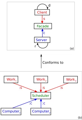
Figure 2: Metamodel for (a) the facade design pattern and (b) and example of a model following the pattern/metamodel
Definition 6 (Match of Pattern) Given a patternPtyped overMand a specificationS, a match m:P→Sof the patternPinSis a specification morphismm:P→S. The specificationS
follows a patternP if there exists a matchm:P→Ssuch thatm(P)conforms toM.
Example 2 (Facade Design Pattern) The facade element in the facade design pattern serves as an interface for subsystems. That is, if a system consists of several subsystems which are inter-acting with each other, the facade design pattern should be followed. In Fig.2a the metamodel for the facade pattern is given. A model following this pattern can be seen in Fig. 2b. The model is a snapshot of a scenario illustrating how certain works are deployed on some com-puters. There are three Client elementsWork1, Work2, Work3 communicating with twoServer elementsComputer1,Computer2via theFacadeelementScheduler.
3.2 Pattern Enforcement
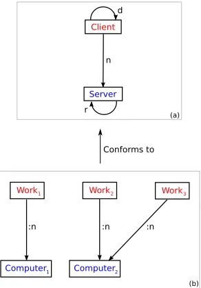
If a patternPis not followed by a specificationS, then the pattern may be enforced by applying a model transformation toS. The precondition for the enforcement of a pattern will then be the source of a model transformation. This is also known as anti-pattern, i.e. a design which is not desired and need to be refactored. An anti-pattern is also defined as a pattern (see Fig.3for an anti-pattern for the pattern in Fig.2).
A model transformation is the automatic generation of target models from source models, according to a transformation definition. A transformation definition is a set of transformation rules that together describe how a source model can be transformed into a target model.
spe-(a)
Conforms to
Work Work
Work1 2 3
Computer1 Computer2
(b) Server
Client
n d
r
:n :n :n
Figure 3: Metamodel for (a) anti patterns and (b) an example of anti pattern
cification morphismr:L→R. An application of a model transformation ruler is given by a pushout construction, see e.g. [BW95] for a definition of pushout.
L
m
r
R
m∗
S
hr,mi S
∗ P.O.
where for each matchm:L→S, a matchm∗:R→S∗ is created.
Definition 8 (Pattern enforcement) Given a pattern P and a specification S, P may be en-forced inSby performing a model transformationT such thatT(S)follows the patternP.
The following example shows the enforcement of a pattern by applying model transformation.
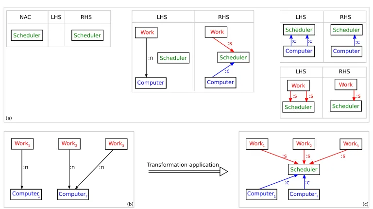
Example 3 (Pattern Enforcement) Building upon Example2. The example illustrates how to refactor a client-server architecture such that it follows the facade design pattern. Given the specification in Fig. 4b, a model transformation enforces the facade design pattern and creates the design in Fig.4c. The model transformation consists of four rules:
1. There should be exactly oneScheduler
2. Every connection between aWorkand aComputeris rerouted via theScheduler
3. There should not be more than one connection between aComputerand theScheduler
Transformation application
Scheduler
Work1 Work2 Work3
Computer1 Computer2
(c)
Work1 Work2 Work3
Computer1 Computer2
(b) Scheduler
Scheduler
NAC LHS RHS RHS
Scheduler Work Computer LHS Scheduler Work Computer RHS LHS Scheduler Work Scheduler Work RHS LHS (a) :s
:s :s :s
:s :s :s :c Scheduler Computer :c :c Scheduler Computer :c :c :c :n :n :n :n
Figure 4: Using transformation rules (a) to enforce the pattern in Fig.2, a model (b) with an anti pattern in it is refactored to a model (c) following the required pattern
3.3 Constraint-Aware Pattern Enforcement
The next step is to take constraints into account while defining, matching and enforcement of patterns. When a constraint-aware pattern is enforced, the constraints of the original specification should be transformed into corresponding constraints in the refactored specification. One way to achieve this is to use constraint-aware model transformations as described in [RRLW10]. In this approach, constraints of the source models are used to control which structures and which constraints should be defined in the target model. Adding constraints to patterns can also be used to specify the intended behavior of the design. This section outlines how constraint-aware patterns are formalised and enforced in view of DPF.
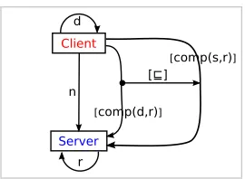
Example 4 (Constraint-Aware Patterns) Building on example3, in Fig.5we add a constraint to the pattern metamodel in Fig.3. The constraint expresses a requirement that if a clientc1 is dependent on a client c2, the host server(s) ofc1 should reach the host server(s) ofc2. This requirement is expressed by the constraint comp(d, s)⊆comp(s, r). That is, the result of the composition ofdwithsshould be included in the results of the composition ofswithr.
Constraints at a modelling level may be expressed as universal constraint on the level below.
Figure 5: Metamodel of the anti-pattern from Fig.3a extended with constraints
Figure 6: Transformation of (A) source universal constraints to (B) target universal constraints
Pattern application
Scheduler
Work1 Work2 Work3
Computer1
(c) Work1 Work2 Work3
Computer2 Computer1 Computer2
(b) :d
:r
:d
:r
:n :n :n
:s :s :s
:c :c
Example 6 (Transformation of Universal Constraint) Building on Example3. Fig.7a shows a specification with a match of the anti-pattern in Fig. 5. The rules from Fig. 4a are used to transform this specification to the specification shown in Fig.7b. The universal constraint in Fig. 6A is transformed to the universal constraint in Fig. 6B. This constraint ensures that if
Work1 is dependent onWork2 and theSchedulerrunsWork1 on Computer1 then theScheduler should runWork2on aComputer2 which is reachable fromComputer1.
4
Related Work
In [BGL09] a formal definition of patterns is given as a set of graphs and graph morphisms, defining a fixed part and some variable regions. Variable regions are used to specify multiple occurrences of sub-patterns. Moreover, triple graphs are used for coordinating models with the pattern. The approach also uses synchronisation graphs to relate structural models and behavioral models. In the DPF-based approach patterns are defined by metamodels. Moreover, a variable region may be represented in the metamodel with multiplicity[0. . .∗]. Coordination of patterns with models are done by conformance and match of patterns.
Pattern-based model-to-model transformation is an algebraic, bidirectional and relational ap-proach to model transformation [LG08] based on Triple Graph Grammar (TGG) [Sch94]. This approach is based on triple patterns which express allowed and forbidden relations between two models, where the models are triple graphs. Triple patterns can be seen as graph constraints for triple graphs, which specify both negative and positive constraints. Pattern-based specifications are compiled to operational TGG rules, which perform forward and backward model transform-ations by graph rewriting. Matches of these patterns are formalised as triple graph morphisms. Furthermore, in [Löw10], graph rewriting is generalised by using span-categories. In the DPF-based approach, universal constraints are used to express requirements which are expressed by triple patterns in pattern-based model-to-model transformations. These constraints are also used to ensure that pattern enforcement is performed in a way that source constraints are transformed adequately to the target models.
In [Grø10] a concrete syntax for definition of input and output patterns of model transforma-tion rules is employed. That is, instead of using the abstract syntax of the modelling languages involved in the model transformation, as done usually, one can define transformation rules em-ploying the syntax used for definition of the models themselves. In addition, this approach offers a collection operator which is used for matching and transformation of collections of similar sub-graphs. This operator is used for the definition of patterns with variable regions. The DPF-based approach employs also a concrete syntax for definition of patterns. Moreover, since patterns are defined by metamodels, variable regions are represented by metamodel elements with variable multiplicity.
5
Conclusion and Future Work
require-ments that should be fulfilled by models. We require that pattern enforcement adequately trans-forms these constraints.
Since patterns are described by metamodels, the relation between anti-pattern and required pattern may be seen as metamodel evolution. In this context, pattern enforcement may be seen as model migration, i.e. transformation of models conforming to the anti-pattern metamodel to models conforming to the required pattern’s metamodel. An interesting line of research in this direction is to find the conditions under which it is possible to automatically generate model migration rules. Some preliminary results about model migration is done in [MRR+10].
An other interesting aspect with patterns is the relation between patterns. Patterns are diagram-matic specifications and it is natural to relate them to each other by specifications morphisms. A further study of different patterns and their relations should be done to obtain a taxonomy of patterns.
References
[BC87] K. Beck, W. Cunningham. Using Pattern Languages for Object-Oriented Programs. Technical report CR-87-43, Tektronix, Inc, September 1987.
[BGL09] P. Bottoni, E. Guerra, J. de Lara. Formal Foundation for Pattern-Based Modelling. In Chechik and Wirsing (eds.), FASE 2009: 12thInternational Conference on Fun-damental Approaches to Software Engineering. LNCS 5503, pp. 278–293. Springer,
2009.
doi:/10.1007/978-3-642-00593-0_19
[BW95] M. Barr, C. Wells. Category Theory for Computing Science (2nd Edition). Prentice
Hall International Ltd., Hertfordshire, UK, 1995.
[Dis03] Z. Diskin. Practical foundations of business system specifications. Chapter Mathem-atics of UML: Making the Odysseys of UML less dramatic, pp. 145–178. Kluwer Academic Publishers, 2003.
[DW08] Z. Diskin, U. Wolter. A Diagrammatic Logic for Object-Oriented Visual Modeling. In ACCAT 2007: 2nd Workshop on Applied and Computational Category Theory.
ENTCS 203/6, pp. 19–41. Elsevier Science Publishers B. V., Amsterdam, The Neth-erlands, 2008.
doi:10.1016/j.entcs.2008.10.041
[GHJV94] E. Gamma, R. Helm, R. Johnson, J. M. Vlissides. Design Patterns: Elements of
Reusable Object-Oriented Software. Addison-Wesley Professional, 1994.
[Grø10] R. Grønmo. Using Concrete Syntax in Graph-based Model Transformations. PhD thesis, Department of Informatics, University of Oslo, Norway, February 2010.
[Küh06] T. Kühne. Matters of (Meta-)Modeling. Software and System Modeling 5(4):369– 385, 2006.
[LG08] J. de Lara, E. Guerra. Pattern-Based Model-to-Model Transformation. In ICGT
2008: 4th International Conference on Graph Transformations. LNCS 5214,
pp. 426–441. Springer, 2008. doi:10.1007/978-3-540-87405-8_29
[Löw10] M. Löwe. Graph Rewriting in Span-Categories. In Ehrig et al. (eds.), ICGT 2010:
5thInternational Conference on Graph Transformations. LNCS 6372, pp. 218–233.
Springer, 2010.
doi:/10.1007/978-3-642-15928-2_15
[Mak97] M. Makkai. Generalized Sketches as a Framework for Completeness Theorems.
Journal of Pure and Applied Algebra 115:49–79, 179–212, 214–274, 1997.
doi:10.1016/S0022-4049(96)00007-2
[MRR+10] F. Mantz, A. Rossini, A. Rutle, Y. Lamo, U. Wolter. Towards a Formal Approach to Metamodel Evolution. In NWPT 2010: 22ndNordic Workshop on Programming Theory. Pp. 52–54. November 2010.
[RRLW09] A. Rutle, A. Rossini, Y. Lamo, U. Wolter. A Diagrammatic Formalisation of MOF-Based Modelling Languages. In Oriol and Meyer (eds.), TOOLS 2009: 47th In-ternational Conference on Objects, Components, Models and Patterns. LNBIP 33,
pp. 37–56. Springer, 2009.
doi:10.1007/978-3-642-02571-6_4
[RRLW10] A. Rutle, A. Rossini, Y. Lamo, U. Wolter. A Formalisation of Constraint-Aware Model Transformations. In Rosenblum and Taentzer (eds.), FASE 2010: 13th
International Conference on Fundamental Approaches to Software Engineering.
LNCS 6013, pp. 13–28. Springer, 2010. doi:10.1007/978-3-642-12029-9_2
[Rut10] A. Rutle. Diagram Predicate Framework: A Formal Approach to MDE. PhD thesis, Department of Informatics, University of Bergen, Norway, 2010.
[Sch94] A. Schürr. Specification of Graph Translators with Triple Graph Grammars. In Mayr et al. (eds.), WG :20th International Workshop on Graph-Theoretic Concepts in Computer Science. Lecture Notes in Computer Science 903, pp. 151–163. Springer,
1994.