Proceedings of the Workshop
Visual Formalisms for Patterns
at VL/HCC 2009
The Pattern Instance Notation: A Simple Hierarchical Visual Notation
for the Dynamic Visualization and Comprehension of Software Patterns
Jason McC. Smith
12 pages
Guest Editors: Paolo Bottoni, Esther Guerra, Juan de Lara
Managing Editors: Tiziana Margaria, Julia Padberg, Gabriele Taentzer
The Pattern Instance Notation: A Simple Hierarchical Visual
Notation for the Dynamic Visualization and Comprehension of
Software Patterns
Jason McC. Smith1
1[email protected], TSRI, Inc, Kirkland, WA
Abstract: Design patterns are a common tool for developers and architects to un-derstand and reason about a software system. Visualization techniques for patterns have tended to be either highly theoretical in nature, or based on a structural view of a system’s implementation. The Pattern Instance Notation is a simple visualization technique for design patterns and other abstractions of software engineering suitable for the programmer or designer without a theoretical background. While based on a formal representation of design patterns, using PIN as a tool for comprehension or reasoning requires no formal training or study. PIN is hierarchical in nature, and compactly encapsulates abstractions that may be spread widely across a system in a concise graphical format, while allowing for repeated unveiling of deeper layers of complexity and interaction on demand. It is designed to be used in either a dynamic visualization tool, or as a static representation for documentation and as a teaching aid.
Keywords:design patterns, visualization, education, comprehension
1
Introduction
Design patterns[GHJV95] are a common and useful mechanism for software developers and designers to document, understand, and reason about the abstractions that are used to create software systems. Notations for visualizing design patterns, however, have required either a very strong background in design theory, or an adherence to the particular structure of an implemented design. The former causes issues with developers who are not trained in the subtleties of abstrac-tion research, while the latter causes issues when considering a design independent of a specific implementation.
The Pattern Instance Notation is a formal visualization technique for representing design pat-terns and other abstractions. PIN provides a simple box-and-line approach that is familiar to most software engineers and designers, yet offers a unique hierarchical abstraction that mirrors the concepts of patterns closely. PIN is suitable for use as a static diagramming notation, but is also intended as a dynamic system for direct interaction by a user investigating a design. It is not intended to be a full replacement for, or formal form of, design pattern definitions. The goal is a pragmatic, simple notation that conveys the underlying connections and relationships in an abstract view of software to assist developers and designers in comprehending and reasoning about the abstractions expressed in their software.
briefly describe the underlying formalisms that inspired the PIN. Next, I will provide a definition of the PIN in its three modes - collapsed, simple, and expanded, and show how each can be used as an adjunct to a standard UML diagram, or as a standalone diagram. Finally, I will discuss ways in which these modes can be utilized in an interactive system for program discovery and understanding.
2
Background
The Pattern Instance Notation has its roots in the System for Pattern Query and Recognition project[SS03,SS07]. SPQR is a comprehensive system of abstraction formalization, detection, and reporting tools that detects instances of known design patterns and other abstractions directly from source code in a language independent manner. PIN was created because the existing graphical notations were often found to be too abstract or too complex to be readily useful for the average practitioner, or too closely tied to the structure of code to properly represent the abstractions that are inherent in patterns, independent of the source code implementation.
This latter point is important because a pattern can be instantiated in a multitude of ways in implementation. SPQR was designed to find those instances that were expressed in a non-direct manner, with relationships being created through transitive chains of interaction, instead of im-mediate and direct expression. An example of this is a chain of method calls that ultimately leads to a relationship between the first method, and thenth method in the chain. This relationship may be precisely what fulfills a design pattern requirement, but it is not directly found in the source code. In these cases, the pieces of a pattern are often scattered across the system in a way that has little to no congruence with the physical or structural view. SPQR’s rho-calculus[Smi05] creates an alternative to the rigid physical locality constraints found in most pattern description work, and transforms the source code into a space defined by the conceptual relationships between the fundamental entities of object-oriented programming.
It is these conceptual relationships, or reliances, that form the basis of a hierarchical pattern language, the Elemental Design Patterns, or EDPs[SS02]. The EDPs are the core building blocks of object-oriented software design, and through well-formed composition and combination, nat-urally and quickly lead to the more familiar design patterns from the literature. Further, as shown in [Smi05], all object-oriented systems can be broken down into a collection of interacting EDPs, and design patterns are necessarily comprised of EDPs combined in familiar forms. PIN was cre-ated to address these needs: simplicity, pragmatism, non-physical locality of pattern expression, and explicit hierarchical information.
2.1 Previous Work
tend to be fairly simple, and are generally easy for a developer to use, being based closely on preconceptions of ‘how software exists’. For pragmatism, these notations do well, but they have a fundamental mismatch with the role-based view of design patterns and abstraction in general.
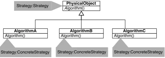
The core issue with notations that follow the structural view of software is that they impose the physical locality mentioned above on the view. The most straightforward example of this is the pattern:role annotation originally developed to augment UML diagrams with basic design pattern concepts[Vli98]. A class, method or field is tagged with a pattern name and a role, as shown in
Figure 1. The roles associated with a particular pattern may be scattered around a UML diagram, making it difficult to see the conceptual interactions. The pieces of the pattern instance are spread across the structural UML notation, and it is up to the viewer to create their own connections in their head. This is an odd burden to place on the user of a visual notation, but is common to all in this group, with the exception of UML Collaboration annotations[RJB04] which does place the collaboration, or pattern instance, as a first-class entity. Collaboration annotations, however, are limited in their abilities. They represent a named abstraction, and provide role names, but do not scale well to finer or coarser granularities that are often useful, as we will see inSection 3.
Algorithm() PhysicalObject
Algorithm() AlgorithmA
Algorithm() AlgorithmB
Algorithm() AlgorithmC
Strategy:ConcreteStrategy Strategy:ConcreteStrategy Strategy:ConcreteStrategy Strategy:Strategy
Figure 1: Pattern:role Annotation tags in UML
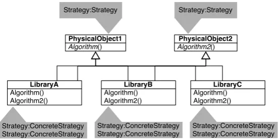
Despite this, these annotations are adequate for cases where a single instance of a particular pattern exists in the diagram, such as when teaching students how a design pattern may map to an implementation. This approach quickly breaks down, however, in real world systems, when multiple instances of a pattern exist, as in even the simple diagram inFigure 2. While both the UML Collaboration notation and the stereotypes described in [DYZ07] do allow for multiple instances, the lack of flexibility in the former and the lack of treating patterns as first class visual entities in the latter make them more difficult to use than necessary. This adds an additional goal for PIN: dealing with multiple instances.
Algorithm()
PhysicalObject1
Algorithm() Algorithm2()
LibraryA
Algorithm() Algorithm2()
LibraryB
Algorithm() Algorithm2()
LibraryC
Algorithm2()
PhysicalObject2
Strategy:ConcreteStrategy Strategy:ConcreteStrategy
Strategy:ConcreteStrategy Strategy:ConcreteStrategy
Strategy:ConcreteStrategy Strategy:ConcreteStrategy Strategy:Strategy
Strategy:Strategy
Figure 2: Pattern:role Annotation tags in UML - multiple instances
PIN is designed to straddle these two realms, striking a balance between the simplicity of a direct modeling notation, and the richness of a concept-based notation, while avoiding the physical locality issues seen in most structural notations, and refraining from the complexity of complete metamodels.
3
Pattern Instance Notation Definition
The goals for PIN as listed above are: pragmatic simplicity for the average developer, support for multiple instances in a single diagram, and a concept-based approach with a clear hierarchical expression. By starting with a basic box-and-line notation, we can add support for these goals in stages, to define the full PIN. First, however, a brief conceptual formalization of PIN can be provided. As in the rho-calculus which inspired this notation, patterns or other abstractions are described as a series of conceptual roles. This can be expressed as a simple tuple of the formPattern(Role1,Role2,Role3...). Such a tuple is the product of reduction rules describing the subpatterns and primary entities and relationships that form it. The recursive nature of the definitions ultimately results in the relationships defined by the denotational semantics of rho-calculus. As an example, the definition for the Decorator pattern is given inEquation 1. Instances of the subpatterns, Object Recursion and Extend Method, are explicitly listed, and the occurrence of the same name in multiple role slots, such asDecorator, means that whatever implementation feature fulfills that role in one subpattern fulfills the other ones as well. For further details on the rho-calculus and the full pattern definition catalog, see [Smi05]. PIN captures this hierarchy of concepts cleanly and effectively when appropriate, and encapsulates the detail when necessary.
ObjectRecursion(Component,Decorator,ConcreteComponent,any)
ExtendMethod(Decorator,ConcreteDecorator,operation)
3.1 Collapsed
The most basic form of PIN fulfills the first two goals, pragmatic simplicity and multiple in-stances, by using the most common diagramming elements: boxes and lines. PINboxes, as shown inFigure 3are simple rectangles, with rounded corners and an optional slightly shaded or thick border. This is to distinguish them from the right-angle corner rectangles used in UML when the two notations are blended, as described later inSubsection 4.2. Each PINbox repre-sents a separate instance of a pattern, and is labeled internally with the name of the pattern or abstraction. It is suggested that the name placement be centered along both axes.
Pattern
Figure 3: Collapsed PIN Instance
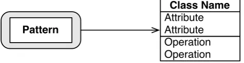
Unidirectional arrows are used to connect instances to entities in UML. An arrow indicates that the instance at the tail end of the arrow uses, or relies on, the UML entity at the head end of the arrow. There is no cardinality associated with the arrows, as each pattern instance is illustrated separately. The relationship here has a different basis than the Uses relationship of UML, and should not be confused with it. The more accurate term, adopted from the terminology of rho-calculus, would be Relies On.Figure 4shows an example of this connection, where the instance of Pattern has a reliance on the class entity Class Name.
Pattern
Operation Operation Attribute Attribute
Class Name
Figure 4: Collapsed PIN Connection
This collapsed PIN format is suitable for quickly connecting a pattern instance graph, or as a shorthand for demonstrating the abstractions in a UML diagram. It has no detail, however, and is most commonly used for sketching out a rough design or as a lightweight mnemonic.
3.2 Standard
The standard PIN notation expands on the next of our intended goals: a concept-based approach. Following on the role-based formalisms of rho-calculus, a pattern is defined as having certain Roles that are fulfilled by the programmatic entities of a system. For instance, from a reading of the common definition[GHJV95], a Decorator instance has Roles ofComponent, Concrete-Component, Decorator,ConcreteDecorator, andoperation. Each of these required class types and methods is fulfilled by a specific entity in the implementation. We saw a simplified ver-sion of this in the collapsed PIN form, where only the critical primary roles were connected to their implementations. Now we build on that to show all the roles, and which classes, objects, attributes or operations they are fulfilled by. It is somewhat analogous to the UML Collabora-tion annotaCollabora-tion[RJB04], but unlike the UML variant, can be used to show design interactions independent of a UML, or implementation-oriented, representation.
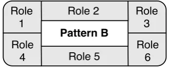
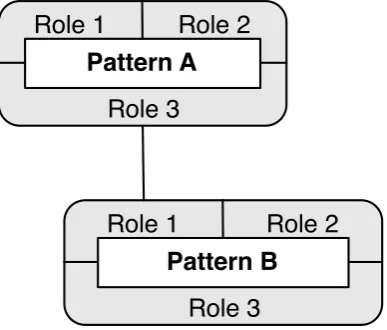
PIN demonstrates this role-based view by providing ‘sockets’ around the edge of the instance PINbox, which are then connected to their fulfilling entities in either other PIN instances, or UML entities. Figure 5 shows this role ring. N roles are represented by N boxes around a central name label. Because experience with SPQR has shown that the number of formal roles in most patterns is less than 6, this is manageable, and demonstrates a clear concept of external connection from the pattern instance. Roles may be arranged around the core in any order, as necessary for clean graph connection. Text may be rotated parallel with the core edges as desired for compactness. As with the collapsed form, shading is often used to visually clarify the role ring, but is optional. Rigidity of form is not the goal here, but a clear expression that a pattern instance, as named in the core, has a number of roles that must be fulfilled by external means.
Pattern A Role 1
Role 2 Role 4 Role 5 Role 6
Pattern B Role 2 Role
1
Role 3
Figure 5: Standard PIN Roles
specific well-formed manner. This is a way of focussing on a design’s conceptual relationships without being distracted by the implementation.
Pattern A
Role 2
Role 1
Role 3
Pattern B
Role 1
Role 2
Role 3
Figure 6: Standard PIN Role Connections
3.3 Expanded
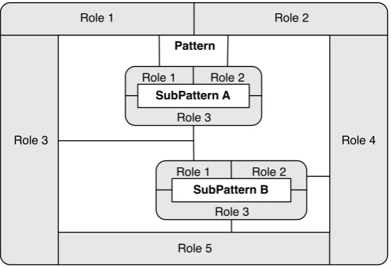
With the PINbox supporting roles, we can meet our final goal: hierarchical expression of pat-tern composition. Just as the role ring expressed the expat-ternal needs of the patpat-tern instance, the expanded PINbox shows the internal conceptual relationships of the instance. As inFigure 7, the basic instance box of the standard notation is physically expanded, by increasing the size of the core box. This provides a canvas on which to draw the sub-patterns that compose the exter-nal pattern, as further PINbox instances. Roles of the sub-patterns are connected to other roles, both internally to other sub-patterns, and externally to the main role ring of the primary pattern, using the solid lines described above. The role ring, particularly when shaded, visually conveys its function as an encapsulation technique, translating the internal conceptual complexity to a simple external interface.
The expansion ability of any non-Elemental pattern means that this process can continue ex-posing deeper layers of the hierarchy. As new instances are revealed, they can be similarly expanded, until only the Elemental Design Patterns are left, and the full conceptual hierarchy is exposed. Since this is done on a per-instance basis, some portions of a diagram can be deeply exposed, with other portions left in the standard encapsulated form. With multiple levels of ex-pansion or contraction, a viewer can find the right balance of abstraction and detail for a specific purpose. This is a highly useful device as a teaching tool, making the conceptual connections tangible to the student. It is also, in a dynamic visualization environment, a powerful tool for the developer or designer wishing to more fully understand a software system.
Role 1 Role 2
Role 5
Role 3 Role 4
Pattern
SubPattern A Role 2 Role 1
Role 3
SubPattern B Role 1 Role 2
Role 3
Figure 7: Expanded PIN Instance
existing notations in this space, and existing formalisms that are appropriate. PIN fulfills the needs of the practitioner, not the theorist, while maintaining a strong theoretical foundation. PIN is simple, concise, and flexible, and applicable to a number of use cases.
4
Example Uses
In this section I will discuss the prime uses of PIN, as both a standalone notation and as an adjunct to other more familiar notations, such as UML.
4.1 Standalone
PIN is appropriate for displaying the conceptual design of a system, independent of implementa-tion constructs such as classes, methods, or fields. It allows a more ‘pure’ view into the design of a system, and lets the developer or designer consider only the abstractions of interest to them at a particular point in time. Expanding instances allows a designer to see further detail of a system, and consider implementation details that may be hidden at higher levels of encapsulation.
In teaching environments, a PIN diagram can show the collaboration and interaction between known abstractions, providing a template for the student that is not tied to a specific implemen-tation language or code structure. For instance,Figure 8, shows that the Decorator pattern from
Concrete Decorator
Component operation
Concrete Component Decorator
Decorator
Object Recursion
Recurser Terminator
Handler
Extend Method
Original Behavior operation
Extended Behavior
Figure 8: PIN Diagram of Design Pattern Definition
4.2 UML Partnership
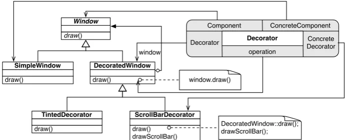
Used in conjunction with UML, PIN takes on a function as an explanatory tool. It allows design to be treated orthogonally to implementation, and the same design in PIN can be mapped to a number of implementations in various languages. The external roles of the instances are con-nected to the UML diagram via the arrow notation introduced inSubsection 3.1.Figure 9shows a very simple example in PIN standard from, with a single instance of the Decorator pattern. The Decorator instance can be collapsed and connected to one or more UML entities based on what the user thinks is the proper level of clarity. InFigure 10, a single connection to the class fulfilling the Decorator role of the Decorator pattern is enough to provide guidance to the viewer. Most patterns have one or two roles that are considered primary, and a practitioner familiar with the design patterns literature will frequently only need a shorthand pointer to the implementation entities in a UML structure diagram to provide understanding.
draw() Window
draw()
TintedDecorator
draw()
SimpleWindow
window
window.draw()
DecoratedWindow::draw(); drawScrollBar(); draw()
DecoratedWindow
draw() drawScrollBar()
ScrollBarDecorator
Decorator
Component ConcreteComponent
operation
Decorator Concrete Decorator
draw()
Window
draw()
TintedDecorator
draw()
SimpleWindow
window
window.draw()
DecoratedWindow::draw(); drawScrollBar(); draw()
DecoratedWindow
draw() drawScrollBar()
ScrollBarDecorator Decorator
Figure 10: Collapsed PIN Instance used with UML
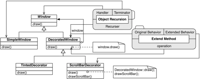
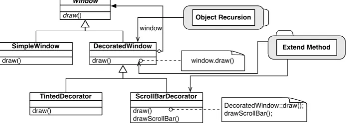
Expansion can be done here as well, and an additional aspect of PIN can be used: peeling. Peeling is related to expansion in that the outer layers of the expanded PINbox are removed. This promotes the inner subpatterns to primary patterns, and the previous connections from the UML entities to the outer role ring are instead extended through to the roles of the previous inner subpatterns. A small tab is added to an edge of the subpatterns to indicate that they are part of a larger pattern instance. This tab is not intended to specify which instance, but instead is just a reminder of their original non-primary status. Figure 11shows the above example, expanded and peeled.
draw() Window
draw()
TintedDecorator draw()
SimpleWindow
window
window.draw()
DecoratedWindow::draw(); drawScrollBar(); draw()
DecoratedWindow
draw() drawScrollBar()
ScrollBarDecorator
Object Recursion Terminator Handler
Recurser
Extend Method Original Behavior Extended Behavior
operation
Figure 11: Peeled PIN instance used with UML
draw() Window
draw()
TintedDecorator
draw()
SimpleWindow
window
window.draw()
DecoratedWindow::draw(); drawScrollBar(); draw()
DecoratedWindow
draw() drawScrollBar()
ScrollBarDecorator
Object Recursion
Extend Method
Figure 12: Peeled and Collapsed PIN instance used with UML
4.3 Dynamic Notation
PIN is useful when used as a static notation, but the flexible expansion and peeling become much more so when implemented in a dynamic environment, such as a GUI based tool. Not only can the expansion and peeling be done on demand, but instances from previously peeled patterns can now be dynamically reconstituted into their original form. The tab annotation to indicate membership in a larger abstraction is an obvious user action trigger for this. When used in this manner, the diagram can be adjusted on the fly to best match the developer’s needs. This interactivity supports a natural process of discovery of the concepts in a system, and lets the developer or designer act on the design and the implementation quite separately, and reveal or encapsulate the design at the appropriate level of granularity. At that point a static representation can be saved for later use.
5
Conclusion
The Pattern Instance Notation was created to support software developers and designers in docu-menting and understanding software systems in a concise and simple format that uses a concept-based approach to provide a cleaner view of design patterns. While firmly rooted in a formal abstraction semantics of software design, it reduces the complexities of a theoretical metamodel down to a system that is natural and intuitive. A flexible notation centered around a single visual entity, the PINbox, provides multiple levels of detail within a single notation, and is suitable for static and interactive visualizations, either on its own, or as an adjunct to more traditional UML or other structurally-based notations. Using PIN to visualize software design results in a flexible system that mirrors the needs of developers and designers in industry, as well as the casual needs of the theoretician or patterns researcher.
Bibliography
[BT06] H. Byelas, A. Telea. Visualization of Areas of Interest in Software Architecture Dia-grams. InSoftVis ’06: Proceedings of the 2006 ACM symposium on Software visual-ization. Pp. 105–114. ACM, New York, NY, USA, 2006.
doi:http://doi.acm.org/10.1145/1148493.1148509
[DYZ07] J. Dong, S. Yang, K. Zhang. Visualizing Design Patterns in Their Applications and Compositions.IEEE Trans. Software Eng.33(7):433–453, 2007.
[Ede01] A. H. Eden. Formal Specification of Object-Oriented Design. InProc. Int’l. Conf. Multidisciplinary Design in Engineering CSME-MDE. Nov 2001.
[GHJV95] E. Gamma, R. Helm, R. Johnson, J. Vlissides. Design Patterns. Addison Wesley, 1995.
[KFGS03] D.-K. Kim, R. France, S. Ghosh, E. Song. A Role-Based Metamodeling Approach to Specifying Design Patterns. InCOMPSAC ’03: Proceedings of the 27th Annual In-ternational Conference on Computer Software and Applications. P. 452. IEEE Com-puter Society, Washington, DC, USA, 2003.
[MHG02] D. Mapelsden, J. Hosking, J. Grundy. Design Pattern Modeling and Instantiation Us-ing DPML. InCRPIT ’02: Proceedings of the Fortieth International Conference on Tools Pacific. Pp. 3–11. Australian Computer Society, Inc., Darlinghurst, Australia, Australia, 2002.
[RJB04] J. Rumbaugh, I. Jacobson, G. Booch. The Unified Modeling Language Reference Manual. Addison-Wesley Professional, 2nd edition, 2004.
[Smi05] J. M. Smith.SPQR: Formal Foundations and Practical Support for the Automated Detection of Design Patterns From Source Code. PhD thesis, University of North Carolina at Chapel Hill, Dec 2005.
[SS02] J. M. Smith, D. Stotts. Elemental Design Patterns: A Formal Semantics for Com-position of OO Software Architecture. In Proc. of 27th Annual IEEE/NASA Soft. Engineering Workshop. Pp. 183–190. Dec 2002.
[SS03] J. M. Smith, D. Stotts. SPQR: Flexible Automated Design Pattern Extraction From Source Code. In18th IEEE Intl Conf on Automated Software Engineering. Pp. 215– 224. Oct 2003.
[SS07] J. M. Smith, D. Stotts.Design Pattern Formalization Techniques. Chapter 7, Intent-Oriented Design Pattern Formalization Using SPQR, pp. 123–155. IDEA Group, Inc, 2007.
[Vli98] J. M. Vlissides. Notation, Notation, Notation.C++ Report, pp. 48–51, apr 1998.