Proceedings of the
Second International Workshop on
Graph and Model Transformation
(GraMoT 2006)
Using Semantic Anchoring to Verify
Behavior Preservation in Graph Transformations
Anantha Narayanan and Gabor Karsai
14 pages
Guest Editors: Gabor Karsai, Gabriele Taentzer
Managing Editors: Tiziana Margaria, Julia Padberg, Gabriele Taentzer
Institute for Software Integrated Systems, Vanderbilt University
Nashville, TN 37203 USA
Abstract: Graph transformation is often used to transform domain models from one domain specific language (DSML) to another. In some cases, the DSMLs are based on a formalism that has many implementation variants, such as Statecharts. For instance, it could be necessary to transform iLogix Statechart models into Mat-lab Stateflow models. The preservation of behavior of the models is crucial in such transformations. Bisimulation has previously been demonstrated as an approach to verifying behavior preservation, and semantic anchoring is an approach to speci-fying the dynamic semantics of DSMLs. We propose a method to verify behav-ior preservation, using bisimulation in conjunction with semantic anchoring. We will consider two hypothetical variants of the Statecharts formalism, and specify the operational semantics of each variant by semantic anchoring, using Abstract State Machines as a common semantic framework. We then establish bisimulation prop-erties to verify if the behavior models of the source and target Statechart models are equivalent for a particular execution of the transformation.
Keywords:Semantic Anchoring, Behavior Preservation, Bisimulation
1
Introduction
The preservation of the behavior of a model is crucial in many kinds of graph transformations. Consider a scenario where different users are exchanging information modeled through State-charts. Since a formalism like Statecharts has many implementation variants [vdB94], it is often the case that the users use different variants. It is then necessary to transform the models from one variant to the other, such as from iLogix Statecharts to MATLAB Stateflow models. Such transformations could be accomplished through Graph Transformations. One related example is [ASK04], which uses graph transformations to translate Simulink/Stateflow models into Hybrid Automata. In all these cases, it is essential that the transformed model preserves the behavior of the source model.
verify behavior equivalence by using bisimulation in conjunction with semantic anchoring. As the practical Statecharts implementations vary in very subtle features that are not very suitable for a case study, we have devised two hypothetical variants with certain key differences that can better illustrate the complexities of the transformation. We will first specify their operational semantics by semantic anchoring, using Abstract State Machines as a common semantic frame-work. This will allow us to generate a behavior model for any instance model. We will then show how we can use bisimulation to check if the behavior models are equivalent. If the be-havior models are equivalent, we can conclude that that particular instance of the transformation preserved the behavior correctly.
Though the source and target domains considered here are very similar, this approach can be applied to other types of transformations as long as the semantics of the source and the tar-get languages can be represented using a common semantic framework such as Abstract State Machines.
2
Background
2.1 Statecharts
Statecharts [Har87] were first proposed by Harel to model the reactive behavior of systems. Statecharts were presented as an extension to conventional state machines, allowing hierarchy, concurrency and broadcast communication. Statecharts are constructed fromstates and transi-tions. States may besimple(basic states),composite(OR states) orconcurrent(AND states). If a system is in a composite state, it is also in exactly one of its direct sub-states. If a system is in a concurrent state, it is also in all of its direct sub-states. Astate configurationis a maximal set of states that the system can be active in simultaneously. Transitions take the system from one state configuration to another. Events are the basic units of broadcast communication. Transitions may be annotated with triggers, guards and actions. Triggers are the events required to activate the transition, actions are events that are broadcast as a result of taking the transition, and guards are boolean conditions that can enable or disable the transition.
Since the introduction of the Statecharts formalism, several variants have been proposed to overcome specific difficulties. A number of them have been surveyed in [vdB94]. One feature that the variants may differ on is whether inter-level transitions (which are transitions that cut across levels of hierarchy) are allowed or not. Another difference may be whether instantaneous states are permitted. Some such differences will be discussed in detail in the case study.
2.2 Semantic Anchoring
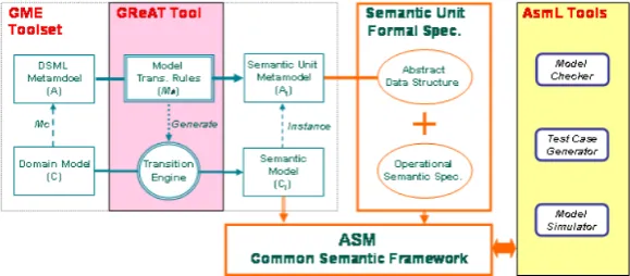
pre-Figure 1: Tool Architecture for Semantic Anchoring
cisely defined. These basic abstractions are calledsemantic units. The behavioral semantics of the DSML is specified as a transformation from the DSML to the selected semantic unit. This last step is called the semantic anchoring. For instance, FSMs can be chosen as a semantic unit to represent the behavior of Statecharts.
The semantics of the behavioral abstraction can be specified using a mathematical model such as Abstract State Machines (ASMs). Microsoft’s Abstract State Machine Language (AsmL) [Asm] provides a powerful language and associated set of tools for programming, simulating and model checking ASM models. The behavior model in the chosen behavioral abstraction, such as FSM, can be mapped to an AsmL Abstract Data Model, which can be simulated or checked using the available tools. The entire toolset is described in [Che06].
Figure1[CSAJ05] shows the tool architecture for specifying operational semantics to DSMLs through semantic anchoring. The GME [LBM+01] MIC toolset is used to define the static se-mantics and integrity constraints of the DSML, and to design the domain models. The semantic anchoring transformation is specified using GReAT [AKL03].
2.3 Bisimulation
Bisimulation [San04] is defined for Labeled Transitions Systems (LTS). Given an LTS (S,Λ,→), where:
S is a set of states,
Λis a set of labels,
and→is a set of transitions, a relationRover S is abisimulationif:
(p,q)∈Randpα
→p0implies that there exists aq0 ∈S such thatqα→q0and (p0,q0)∈R,
and conversely,
qα
→q0implies that there exists ap0∈S such thatpα→p0 and (p0,q0)∈R.
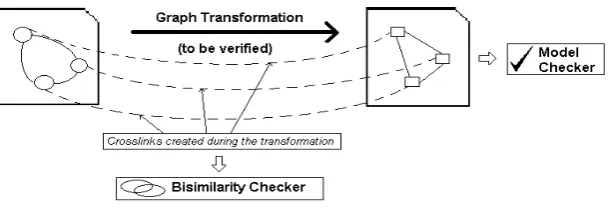
Figure 2: Architecture for verifying reachability preservation in a transformation
we can compare the equivalence of two transition systems by considering a global set containing both the systems’ states.
We can also consider different “flavors” of bisimulation by varying the definition of transitions and labels. If we replace the transition→by aweak transition⇒, we get the definition of aweak bisimulation[HMS06]. Weak bisimulation allows us to compare the equivalence of systems at a level that is not as fine-grained as strict bisimilarity. Suitably defining what constitutes observ-able states and transitions, we can check if two transition systems have a weak bisimilarity. This will allow us to conclude whether the transition systems are behaviorally equivalent for all prac-tical purposes, though there may not be a fine-grain equivalence. For instance, we may choose to ignore internal representations of data or intermediate states when comparing the transition systems for equivalence.
2.4 Verifying Instances of Graph Transformations
In an earlier work [NK06], we proposed a method for using bisimulation to verify each instance of a graph transformation. We believe that the strategy to verify each instance is less complex and more practical, as opposed to devising a correctness proof for the transformation itself, which may be intractable.
In this approach, we use bisimilarity to check if a reachability property is preserved by a certain instance of a transformation. Figure2 shows the basic architecture used for the verifi-cation. The model transformation creates temporary associations between the source and target elements, which are used to trace the equivalence relation R. These links are then used by a bisimilarity checker, to check if this particular instance of input and output models preserve the same reachability behavior. If this check succeeds, the results of a model checker on the output model instance can be applied to the input model instance as well.
3
Verifying Behavior Preservation
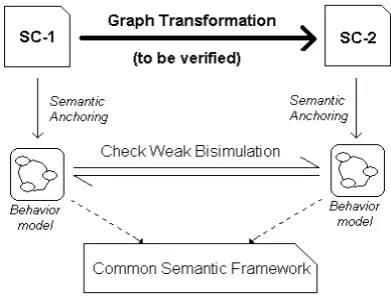
Our approach to verifying behavior preservation relies on establishing a weak bisimilarity be-tween the transition systems representing the behaviors of the source and target models. Figure
Figure 3: Framework for verifying behavior preservation using a common semantic framework and weak bisimilarity
We will use non-hierarchical FSMs as a semantic unit to represent the behavior of the source and target DSMLs. The semantic anchoring process will result in flat FSM representations of the source and target instances. We will then verify if there is a weak bisimulation based on some criteria, as explained in the following sub-sections.
3.1 The Source and Target Languages
The popular Statecharts variants used currently vary in a number of subtle issues. For the sake of simplicity, we will use two hypothetical variants, calledVariant 1andVariant 2, which differ in a small set of features that can be defined clearly. For this case study, we will only consider the synchronous time model. We will now list their features and their semantics.
3.1.1 Compositional Semantics
A language is said to have compositional semantics if the semantics of a compound object is completely defined by the semantics of its subcomponents. In other words, we do not have to look at the internal syntactical structure of the subcomponents. Such semantics are useful in verification. It is easy to see that compositional semantics is violated by allowing inter-level transitions and state references. Inter-level transitions are transitions that cut across levels of hierarchy. State references are a mechanism to allow the execution of a transition based on whether a certain parallel component is active, expressed as trigger conditions such asin(State). In our case study, we will allowVariant 1to have inter-level transitions and state references, and not allow them inVariant 2.
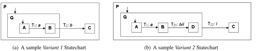
Figure4(a)shows aVariant 1Statechart, where transition T2is inter-level. Figure4(b)shows
aVariant 2Statechart, which tries to simulate the semantics of theVariant 1Statechart, by using a self-termination state to replace the inter-level transition. What happens if the transition T2in
Figure4(a)has an actionE? InVariant 1,Ewill be active when the system enters state C, but in
(a) A sampleVariant 1Statechart (b) A sampleVariant 2Statechart
Figure 4: Sample Statechart models
in the step following the one in which they occur, and not in subsequent steps1). The semantics will be better reproduced if stateDin Figure4(b)is aninstantaneous state. Instantaneous states will be discussed in the next subsection.
We must note that it may not be possible to represent all Variant 1Statecharts asVariant 2
Statecharts. Our objective is not to find aVariant 2representation of anyVariant 1Statechart. Rather, it is to verify whether aVariant 2Statechart generated by a graph transformation can be accepted as behaviorally equivalent to theVariant 1Statechart that was the input to the transfor-mation.
3.1.2 Instantaneous States
An instantaneous state is a state that can be simultaneously entered and exited in a single step. Instantaneous states are not allowed in most common Statecharts variants. We will allow in-stantaneous states inVariant 2Statecharts, with the semantics that a step is not complete until there are no instantaneous states in the final state configuration of that step. The sequence of transitions leading to the final state configuration constitute a macro step, which is considered to be executed in zero time2. Events available at the start of the macro step are available through-out the macro step, and actions on any of the transitions in the macro step will be available in the step following the macro step. For providing finer semantics, we introduce the notion of instantaneous actions toVariant 2Statecharts, which will be available in the same step. In Fig-ure4(b),Dwill be an instantaneous state, andiwill be an instantaneous action. The sequence T21, T22 will form a macro step, with Bas the starting state andC as the ending state. To an
external observer, the instantaneous state Dand instantaneous actioniwill not be visible, and the macro step will appear to be a transition whose triggers and actions will be the aggregate of the triggers and actions of the sequence of transitions. In other words, the macro step will be identical to a transition whose trigger is the conjunction of the triggers for each micro step, and all the trigger events must be enabled at the start of the macro step. The conjunction of all the non-instantaneous actions will be available for the step following the macro step. The effect of the macro step (T21, T22) in Figure4(b)will be identical to transition T2in Figure4(a).
(a) StatechartVariant 1 (b) StatechartVariant 2
Figure 5: GME Meta-models for Statechart Variants
3.1.3 State References
Some Statecharts variants allow triggers to be specified by referencing the activity of other, par-allel states. For instance, the conditionin(S)is true when stateSis active, and entering or exiting
Swill result in eventsen(S)andex(S)respectively. We will allow state references inVariant 1, and not inVariant 2. The graph transformation that will generate theVariant 2Statechart will re-place the events foren(S)andex(S)when necessary, but will not handle the conditionin(S). The replaced events will be considered equivalent when verifying behavior preservation. Variant 1
Statecharts which use the conditionin(S) cannot be transformed by the graph transformation which we will consider in the case study (in(S)can be simulated by a system of self loops, but we chose not to implement it in the case study, to avoid overly complicating the transformation). Figures5(a)and5(b)show the GME meta-models for the two Statechart variants for the case study. The GME modeling environment allows connections to only reside under a single parent. Thus, inter-level transitions must be represented by using references to states that are under another parent. The absence of a ConnectionRef prohibits inter-level transitions in Variant 2. States can be marked as instantaneous in Variant 2. The absence of state references in Variant 2 is enforced by the operational semantics defined by semantic anchoring for this variant.
(a) forVariant 1sample (b) forVariant 2sample
Figure 7: FSM semantic models
3.2 Operational Semantics Using Semantic Anchoring
We will use a flat (non-hierarchical) FSM as the semantic unit to represent the behavior of the Statecharts variants. The meta-model of the semantic unit is shown in Figure 6. The FSM model allows instantaneous states and events, and can model the behavior of both the Statecharts variants discussed above. The semantics of this FSM semantic unit is defined in AsmL [Asm], the Abstract State Machine Language developed by Microsoft Research. This is done by specifying an Abstract Data Model in AsmL, corresponding to the constructs of the FSM semantic unit. For instance,Eventsare modeled as below:
interface Event
structure ModelEvent implements Event structure LocalEvent implements Event structure InstantEvent implements Event
ModelEvent models events input to the model,LocalEventmodels the events generated in a step, andInstantEventsmodels events generated by instantaneous actions, which will be avail-able in the same step.
The FSM itself, the states and the transitions are modeled using AsmLclassconstructs:
class FSM id as String
var outputEvents as Seq of ModelEvent var localEvents as Set of LocalEvent ...
class State id as String
var active as Boolean = false var instantaneous as Boolean
var outTransitions as Set of Transition ...
class Transition ...
The FSM behavior is modeled using operational rules on the data structures. The operational rules define the step semantics of the FSM instance’s reaction to input events. These rules are called during the execution of the model in AsmL. The FSM instance’s reaction is simulated by updating the data fields and activating the enabled transitions. The AsmL model of the instances can be obtained by instantiating the states and transitions based on the model. The details of creating the AsmL abstract model can be found in [CSAJ05].
The specification of the behavior of the Statecharts variants will be expressed via semantic anchoring, as a transformation from the Statechart model to the FSM semantic unit. Figure7(a)
Figure 8: Sample GReAT rule
will be represented by a unique state in the FSM. For instance, the stateP Q Ain Figure7(a)
represents the state configuration consisting of the states P,QandAin Figure 4(a). The next step is to transform the transitions. The transitions are extracted from the Statecharts model, and the source and target state configurations are determined. The corresponding unique states in the FSM are located, and a transition is constructed between them. The trigger, action and guards are then updated in the FSM model.
This transformation of the Statechart model into the FSM semantic unit is a behavior speci-fication, and itself is not verified. We may use the technique described in [NK06] to verify the behavior model by bisimulation if necessary, but the behavior specification may be considered straightforward enough to not require further verification. We are mainly interested in verifying the transformation between the Statechart variants, and not the behavior specification of each variant.
3.3 Setting up the Transformation
We will now describe the graph transformation for our case study. This transformation will take aVariant 1Statechart and convert it into aVariant 2Statechart.
The main tasks of this transformation will be to convert inter-level transitions inVariant 1into normal transitions inVariant 2and to replace any state referencing actions by regular actions. Compositional semantics can be developed by replacing inter-level transitions with concepts called self-start and self-termination. In Figure 4(b), the state D can be thought of as a self-termination state, with the help of which the sequence of transitions T21, T22replace an interlevel
transition. Similarly, self-start states can be used in the case of interlevel transitions entering a state and terminating in one of its substates.
In the transformation, every state in the input Statechart is first copied on to the output. Fig-ure8shows a simple graph transformation rule in GReAT, where a new state is created in the
in the same parent, a transition is created in the output between the corresponding source and destination states. If the transition is inter-level, then a self-start or self-termination state is added to the deeper of the two states, and the parent is marked as the source or target. The process is repeated until the source and target states are under the same parent. An automatic system of naming and numbering the intermediate instantaneous states and actions will ensure that each inter-level transition is reproduced uniquely.
If there are state references in the input model, they will be copied in the output model as normal events, using a special naming convention for identification. All such events will then be added as actions to all transitions into or out of the respective states being referenced. For instance, if a trigger en(S)is used in a Variant 1Statechart, it will be replaced byen Sin the output, and the action en Swill be added to all the transitions into stateS in the output. The occurrence ofin(S)in the input model will be flagged as an error.
3.4 Verifying Behavior Preservation
Our objective here is to verify if a certain instance of the transformation produced aVariant 2
Statechart that preserved the behavior of theVariant 1Statechart given as input. To verify this, we get the semantic model of the input instance and the semantic model of the output instance, and check if they are behaviorally equivalent. This is done by establishing a weak bisimulation relation between the two behavior models.
3.4.1 Weak Bisimulation
According to the semantics we have described, we consider the two Statechart models in figures
4(a) and4(b) to be behaviorally equivalent. But it is obvious that the two behavior models in Figures7(a)and7(b)are not bisimilar. We thus turn to a practically useful notion of bisimilarity that will help us in this scenario, the notion ofweak bisimilarity.
In Figure7(b), the state P Q Dand the action iare instantaneous. To an external observer, the sequence of transitions T21, T22will appear identical to the transition T2 in Figure7(a). To
the observer, the two systems are behaviorally equivalent, even though they may vary internally. Weak bisimulation allows us to weaken the notion of what constitutes a transition, allowing us to set the granularity at which we accept two systems as behaviorally equivalent. In our scenario, we argue that it is acceptable to consider only non-instantaneous states as states of the transition system, and a transition as one that goes from one non-instantaneous state to another, passing through any number of instantaneous states. We consider such transitions as a singleweak tran-sition, whose trigger and action are the aggregate of the series of transitions, disregarding all instantaneous states and actions.
We now rephrase our earlier definition of bisimulation, to define a weak bisimulation for FSM models. We define an equivalence relation R between the non-instantaneous states of two FSM models, for the current study, by simply stating that two statesp and q are in R if they have the same label. Given this equivalence relation, we define a somewhat novel definition of weak bisimulation that is useful for our purpose:
implementation, we representα as a comma separated list of the events that are the triggers and
the actions of the transition. In the case of a weak transition, this list will include all the non-instantaneous events that are the triggers and the actions of the sequence of transitions which constitute the weak transition). According to this definition, the FSM models in Figures7(a)and
7(b)are weakly bisimilar.
3.4.2 Checking for Weak Bisimulation
To verify weak bisimulation, we will first reduce the FSM into non-instantaneous states and weak transitions. This is done by tracing through the FSM model, and aggregating any sequence of transitions through instantaneous states. In this case, onlyVariant 2Statecharts will result in FSM models with instantaneous states, and the reduction step is not required for FSM models of
Variant 1Statecharts.
The next step is to establish the equivalence relation R. For this study, we will consider two states p andq to be in R if they have the same label. Our transformation is set up in such a way that newly created states in theVariant 2Statechart model are labeled depending upon the
Variant 1state they were created from. The FSM states are similarly labeled depending on the labels of the states in the Statechart state-configuration that they represent. We will consider that two states are equivalent if they represent the same configuration in the two Statecharts.
After these two steps, for each of the FSMs, we list all the states in a table, followed by all the outgoing transitions for each of these states. We then step through the states one by one, verifying that the weak bisimulation holds according to the definition above. After stepping through the list of states for both the FSMs, we can conclude whether the generatedVariant 2Statechart is behaviorally equivalent to the inputVariant 1Statechart.
4
Related Work
4.1 Graph Transformation Based Operational Semantics
4.2 Certifiable Program Generation
[DF05] considers the problem of verification of generated code by focusing on each individual generated program, instead of verifying the program generator itself. The generator is extended such that it produces all logical annotations that are required for formal safety proofs in a Hoare-style framework. These proofs certify that the program does not violate certain conditions during its execution. While the proofs in this case are not related to semantic correctness, the idea of providing an instance level certificate of correctness instead of proving the correctness of the generator has been a great motivation for our ideas.
5
Conclusions and Future Work
Semantic anchoring is a useful method for formally specifying the dynamic semantics of DSMLs. We have shown here that it allows us to use bisimulation to verify behavior equivalence across a transformation. This technique is especially useful in cases where it is hard to compare the source and target languages directly. As long as their behavior can be specified using a com-mon semantic framework, we can verify behavioral equivalence by using bisimulation. We have also shown that weak bisimulation is a practical way to determine acceptable behavioral equiv-alence. As in [NK06], we believe that it is more practical to verify whether an instance of a transformation succeeded in preserving behavior, instead of providing a proof of correctness for the transformation itself.
Further research in determining semantic units that can represent a wide variety of DSMLs will allow us to use this technique for a larger range of transformations. We may also consider representing a specific behavioral property using semantic anchoring, as opposed to the complete operational semantics of the language. This will allow us to check the preservation of a specific behavior in languages that are otherwise very different. The checking of weak bisimulation may also be refined to be more efficient.
Acknowledgements: This material is based upon work supported by the National Science Foundation under Grant No. 0509098. Any opinions, findings and conclusions or recommenda-tions expressed in this material are those of the author(s) and do not necessarily reflect the views of the NSF.
Bibliography
[AKL03] A. Agrawal, G. Karsai, A. Ledeczi. An end-to-end domain-driven software develop-ment framework. InOOPSLA ’03: 18th annual ACM SIGPLAN conference on OOP, systems, languages, and applications. Pp. 8–15. ACM Press, New York, NY, USA, 2003.
[vdB94] M. von der Beeck. A Comparison of Statecharts Variants. InProCoS: Proceedings of the Third International Symposium Organized Jointly with the Working Group Provably Correct Systems on Formal Techniques in Real-Time and Fault-Tolerant Systems. Pp. 128–148. Springer-Verlag, London, UK, 1994.
[Che06] K. Chen. A Semantic Anchoring Infrastructure for Model-Integrated Computing. PhD thesis, Vanderbilt University, Nashville, TN 37203, Aug. 2006.
[CHM00] A. Corradini, R. Heckel, U. Montanari. Graphical Operational Semantics. InICALP Satellite Workshops. Pp. 411–418. 2000.
citeseer.ist.psu.edu/corradini00graphical.html
[CSAJ05] K. Chen, J. Sztipanovits, S. Abdelwahed, E. K. Jackson. Semantic Anchoring with Model Transformations. InECMDA-FA. Pp. 115–129. 2005.
[CSN05] K. Chen, J. Sztipanovits, S. Neema. Toward a semantic anchoring infrastructure for domain-specific modeling languages. InEMSOFT ’05: Proceedings of the 5th ACM international conference on Embedded software. Pp. 35–43. ACM Press, New York, NY, USA, 2005.
doi:http://doi.acm.org/10.1145/1086228.1086236
[DF05] E. Denney, B. Fischer. Certifiable Program Generation. InGPCE. Pp. 17–28. 2005.
[Har87] D. Harel. Statecharts: A visual formalism for complex systems.Science of Computer Programming8(3):231–274, 1987.
doi:http://dx.doi.org/10.1016/0167-6423(87)90035-9
[HMS06] W. Harwood, F. Moller, A. Setzer. Weak Bisimulation Approximants. In CSL’06: The 15th International Conference on Computer Science Logic. Lecture Notes in Computer Science, Szeged, Hungary, 2006.
[LBM+01] A. Ledeczi, A. Bakay, M. Maroti, P. Volgyesi, G. Nordstrom, J. Sprinkle, G. Karsai. Composing Domain-Specific Design Environments.Computer34(11):44–51, 2001.
doi:http://dx.doi.org/10.1109/2.963443
[Mar92] F. Maraninchi. Operational and Compositional Semantics of Synchronous Automa-ton Compositions. InCONCUR ’92: Proceedings of the Third International Con-ference on Concurrency Theory. Pp. 550–564. Springer-Verlag, London, UK, 1992.
[San04] D. Sangiorgi. Bisimulation: From The Origins to Today. In LICS ’04: Proceed-ings of the 19th Annual IEEE Symposium on Logic in Computer Science (LICS’04). Pp. 298–302. IEEE Computer Society, Washington, DC, USA, 2004.
doi:http://dx.doi.org/10.1109/LICS.2004.13
[Var04] D. Varr´o. Automated Formal Verification of Visual Modeling Languages by Model Checking.Journal of Software and Systems Modeling3(2):85–113, May 2004.