Design of a Single-Range Controller for the
Pressure Control of a Combustion Chamber
A. Nassirharand
and H. Karimi
1In this paper, a systematic procedure for design of a combustion chamber pressure control system is presented. The procedure is applied to a typical liquid propellant engine and the performance of the resulting new control system is compared with that of the present one. In this research, the nonlinear and dynamic mathematical model of the engine, which includes both soft and hard nonlinearities, is used. The systematic controller design procedure is based on describing function models of the engine coupled with the factorization theory.
INTRODUCTION
The combustion chamber pressure control system is one of the most important parts of a liquid propellant engine. A class of regulators, which is used to control the combustion chamber pressure, is composed of complicated hydraulic control valves. These control valves have many disadvantages. For example, the development of nonlinear and dynamic mathematical models of such control valves is very time consuming and dicult. When such models are developed and incorporated with the rest of the engine model, the execution time of the simulation code is considerably increased. Another disadvantage is that the control valve may accept only one set point (the set point is the desired pressure value of the combustion chamber that the control system must maintain). Therefore, it is desirable to design an alternative pressure control system which would involve microprocessor-based reg-ulators. Such pressure regulators could accept various set points by software. The advantages of regulators that could accept various set points are: (1) The nal desired pressure value could be reached at speci ed stages in order to reduce the eects of water-hammer as well as excessive overshoot of the pressure inside the combustion chamber and (2) To reduce the generated impulse after the engine shut down command is issued
*. Corresponding Author, Farab Co., No. 6, Shahamati St., Vali-e-Asr Ave., Tehran, I.R. Iran.
1. Department of Mechanical Engineering, Khage Nassir-Al-Deen Toosi University of Technology, Tehran, I.R. Iran.
again, in this case, the combustion chamber pressure is reduced from its steady-state value to zero at speci ed stages.
There are limited references (in the open litera-ture) on the design of a combustion chamber control system. A class of literature on dynamic analysis and control system design for liquid propellant engines is limited to linearized models of the engine utilizing a linear systems theory 1,2] therefore, such designs would not be as robust as if the design were based on a nonlinear model of the engine. In the other class, a nonlinear system design approach is employed utilizing nonlinear systems design techniques for use with reusable rocket engines 3] and the design of the regulator loop is assumed to be based on a standard robust design that is used for linear systems. The work presented herein, for the design of the regulator control loop, is fully based on a dynamic and nonlinear mathematical model of the engine with no restriction on type of nonlinearity, order of dierential equations, arrangement of nonlinearities and number of nonlinear terms. The only restriction is that the mathematical model must be representable in the following standard state variable dierential equation form:
_
x(t) =f(xut) (1)
y(t) =g(xut): (2) To the best of the authors' knowledge, this is the rst work in the area of combustion chamber pressure control based on the application of describing function approach coupled with the factorization theory.
There are a number of control system design techniques for nonlinear systems. Some of the popular techniques are: geometric transformation, high-gain feedback, Liaponouv and relay structure, Quantitative Feedback Theory (QFT), optimal, adaptive and de-scribing functions. The geometric and relay structure approaches have made major strides in solving dicult nonlinear control problems 4-7]. However, unlike the describing function or QFT approach, these techniques may not be applied to nonlinear systems with dis-continuous terms. The QFT approach has shown to be eective in solving nonlinear control problems of a general nature 8]. One of the primary drawbacks of this technique is that, unlike the describing function approach, a high order controllers result may require application of a model reduction technique. Adaptive techniques, using update laws based on a Liaponouv analysis, as well as optimal approaches based on a Fourier approximation, have also been developed 9,10]. However, the use of controller design, based upon either of these approaches, is usually justi ed if the classical control theory is not applicable. It should also be kept in mind that adaptive or optimal control laws are usually very dicult to implement. Traditionally, ordinary Describing Function (DF) techniques have primarily been used for system analysis (e.g., limit cycle prediction). In recent years, systematic design approaches, based on describing function techniques, have enjoyed considerable success in achieving \robust" feedback systems that directly take into account plant sensitivity issues 11-13]. In this research, a describing function approach, coupled with a factorization theory, is used for design of the combustion chamber pressure control system. The primary reason for this selection is that the engine model is of the form given by state variable equations of the form given by Equations 1 and 2 and describing function approach is inherently capable of handling such nonlinear models. Of course, the QFT approach is also capable of dealing with such models. However, as was mentioned, this approach results in high order controllers.
The problem statement for the pressure con-troller for the combustion chamber can be stated as follows: Given the computer model of a liquid propellant engine, how does one design a controller that would control the pressure of the combustion chamber? The primary contributions of this work are three-fold: (1) Development of a new, single-range linear controller design procedure for use with highly nonlinear systems, whose mathematical model is of a general nature, (2) A new MATLAB command that may be used for model matching of linear systems and (3) Application of the presented controller design procedure and the associated software for pressure control of a speci c liquid propellant engine combustion chamber.
DESCRIPTION OFTHE CONTROLLER
DESIGN PROCEDURE
The control system design procedure is systematic and involves the following 5 steps.
Step 1 Speci cation of the desired reference linear model,
Step 2 Obtaining the describing function models of the plant and selection of a nominal model, Step 3 Identi cation of the linear model of the
nom-inal frequency domain model of the previous step,
Step 4 Design of a controller, based on the factoriza-tion approach,
Step 5 Veri cation of the design.
The above design procedure results in a single-range linear controller for the nonlinear system under study. Step 1 is user de ned and the user must specify the model of the process that he wants to mimic. In most cases, the desired transfer function would be a second-order transfer function that possesses the desired dominant poles and satis es the desired steady-state error conditions. The user may translate the time and/or frequency performance measures to the desired natural frequency and the desired damping ratio by considering the performance speci cation equations noted in 14] then, the steady-state error speci cations determine if a zero is also required. The zero may be determined from relations for de nition of a steady-state error. A procedure is also outlined in 15] for synthesis of the desired transfer functions with mixed (time and frequency) performance measures.
Step 2 requires knowledge of the operating regimes of interest. Note that, unlike operating points, operating regimes are characterized by the range of expected amplitudes and frequencies of the excitation signal. For the expected amplitudes of the excitation signals, one may use those values that correspond to the desired values of the set point. For example, for the case of regulating the pressure of the combustion chamber, one may use the steady-state values of the positions of the regulator valve control piston, such that those values result in the desired values of the com-bustion chamber pressures. Note that the mentioned steady-state values of the position of the regulator valve control piston are known by the design alternatively, the control system designer may determine the desired steady-state values of the position of the regulator valve control piston by simulation and by noting those values of the position of the regulator valve control piston that result in the desired values of the combustion chamber pressure. The expected frequencies of excitation are usually determined from the knowledge of the natural frequency of the system. As a rule of thumb, the lower
range would be about two decades below the natural frequency of the system and the upper frequency range would be about one decade above the natural frequency of the system. Alternatively, the user may initially set the lower and upper frequency ranges to 0.1 rad/sec and 50 rad/sec, respectively. Then, the pseudo-frequency response plots are generated. If the low frequency response portion is not characterized, then the lower frequency range may be lowered by one decade and so on until the low frequency response portion is characterized. The upper frequency range is also increased if the high frequency gain of the pseudo frequency response is substantial. Then, a Fourier based approach is used to obtain the describing function models 16]. These models are obtained by rst exciting the plant by a known input of the following form:
u(t) =u0+acos(!t) (3)
whereu0is the DC component of the input signal,u(t),
and a is the amplitude level of the excitation signal. Then, the dynamic equations of motion are numerically integrated to obtain the output as a function of time,
y(t). Then, the Fourier integrals for period k are calculated wheny(t) is at steady-state. These integrals are given by the following.
Imk= kT
Z (k;1)T
y(t)e;jm!tdt (4)
where, k= 12:::m= 012::: andT = 2=!. The constant or DC component of the response is given by
I0k and the pseudo-transfer function at discrete
fre-quencies, which is represented by the complex number
G1k(j!u0a),
G1k(j!a) =
!I1k
a : (5)
In order to analyze the importance of the higher harmonic eects, one may evaluate:
Gmk(j!u0a) =!Imk=a m= 23
: (6)
For a given excitation amplitude, a, Equation 5 at discrete frequencies over the range of the user-de ned frequency range of interest is evaluated to obtain the describing function model of the nonlinear plant. This procedure, for various user-de ned excitation ampli-tudes, is repeated to obtain a number of describing function models of the nonlinear plant.
Once the describing function models are obtained, one of these models is selected as the nominal model. Normally, the nominal model would be the one in which the excitation signal would correspond to the
normal operating conditions of the plant in the absence of disturbances, in the absence of loss of sensory devices, or in the absence of any perturbations of the plant. Note that the assumption is that one describing function model of the system adequately describes the dynamic behavior of the system otherwise, a dual-range or a multi-dual-range controller design approach may have to be employed 12,13]. In any case, it is rec-ommended to study the eectiveness of a single-range linear controller before a more complicated controller design procedure, such as a dual-range or a multi-range nonlinear approach, is adopted. In applications where nonlinearity eects are not dominant, the spread in describing function models would not be signi cant and, therefore, a single-range linear controller would suce.
Step 3 requires identi cation of a linear model whose frequency response data matches that of the nominal describing function model of the previous step. Since the describing function models are representative of nonlinear systems, the standard relation between the two components of the frequency response data that exist for linear systems, does not hold for describing function models. Therefore, care must be taken when tting the pseudo frequency response data, as described in 17]. The outcome of this step is a linear model described in terms of a transfer function.
Step 4 is based on the work that was earlier represented in 18] and the controller design equation that was developed there is utilized. The controller design equation is of the following form:
AX=B (7)
where A and B are known and are in terms of the coecients of coprime factors of the linear model of the previous step, the coecients of coprime factors that are a solution to the Bezout identity, the coecients of the desired linear model of Step 1 and the frequency range of interest. VectorX contains the coecients of the function parameter,r(s), that must be substituted in the celebrated Youla parameterization equation to obtain the desired controller. In this research, a new MATLAB command is developed, which is of the following form:
rc] =getrcs(mnw1w2hghd) (8) where mis the degree of the numerator polynomial of
r(s)nis the degree of the denominator polynomial of
r(s)w1 is the lower limit of the frequency range of interest, w2 is the upper limit of the frequency range of interest,his the integration step-size,gis the linear model of Step 3 and hd is the desired linear model of Step 1. The output of the command is the function parameterr(s) and the desired controllerC(s). Finally, in Step 5, the design is veri ed.
NUMERICAL EXAMPLE
The controller design approach outlined above is ap-plied to a problem of the sort encountered in pressure control of a combustion chamber of a liquid propellant engine. The nonlinear and dynamic computer model of the liquid propellant engine is utilized to design a controller for the combustion chamber. The controller design procedure steps are executed as follows. In Step 1, the desired transfer function is identi ed in terms of a linear second-order transfer function that exhibits the desired behavior. The identi ed transfer function is of the following form:
hDyu= s2+ 36100s+ 100: (9)
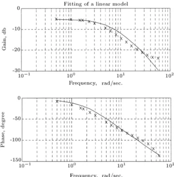
In Step 2, the describing function models are obtained as outlined in the previous section and are depicted in Figure 1. Notice that the spread in these models is not signi cant and, therefore, it may be concluded that a single-range linear controller might suce. The describing function model that was close to the nominal operating conditions was selected for system identi ca-tion purposes of the next step. In Step 3, the MATLAB command, INVFREQS, is used to identify a linear model. Note that this command takes into account the tting concerns that were mentioned in the previous step. The identi ed linear model is of the following form:
G(s) = s2+ 52138:81s:52+ 253:47: (10)
The quality of this t is shown in Figure 2. In Step 4, the developed MATLAB command, getrcs, that was
Figure1. Describing function models of the process.
Figure2. Fitting of the nominal describing function model.
described in the previous section, is used to obtain the following controller:
C(s) = 0:7219s2+ 38:12s+ 183:00
s2+ 36s : (11)
The inputs for thegetrcscommand arem=n=3w1 = 0:01w2 = 5h= 0:01hd=hdyug=G(s). Finally, in Step 5, the design is veri ed. The veri cation results are shown in Figure 3. In the beginning, the pressure set point is set to one unit and, later, this set point is arbitrarily changed to 1.177 and 0.935 units, in order to verify that the regulator could accept various set points. In Figure 3, there are three curves: (1) The experimental results of the engine with the present hydraulic regulator, (2) The simulation results of the
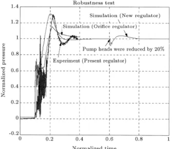
engine with the present regulator modeled as an ori ce and (3) The simulation results of the engine with the new regulator. By comparison of these three curves, the following important point may be noted. One of the problems associated with the present pressure control system is that response overshoots. The curve, corresponding to the new regulator design with a second set point, demonstrates that initial overshoot is not due to the regulator. In fact, the initial overshoot is due to the design of the starter of the engine. With the new design, one may redesign the starter to bring the combustion chamber pressure to a lower value and, then, the new regulator would be able to bring the pressure to its desired value without any signi cant amount of overshoot, as demonstrated in Figure 3 (see the behavior corresponding to the second set point command of the curve entitled \Simulation + New Regulator"). The robustness test is performed by causing a 20% reduction in the pump heads and the results are shown in Figure 4. From this gure it is concluded that the design is also robust because a describing function model is one of the most eective models to achieve a robust design.
SUMMARY ANDCONCLUSION
The goal of this research was to develop a systematic controller synthesis procedure that could be used to replace the existing complicated hydraulic combus-tion chamber pressure control system with a simple microprocessor-based one. This goal was met and the details of the controller synthesis procedure and the associated software were described in detail. The developed controller synthesis procedure is composed of 5 steps and is a speci c procedure for the design of single-range linear controllers for nonlinear plants of a
Figure4. Robustness of the designed controller.
general nature. The synthesis procedure is based on describing function models of the plant and the factor-ization theory. The results of this research indicate that it is adequate to design a single-range controller for the pressure control system of the combustion chamber and that some of the present complicated, hydraulically-based pressure control systems may be replaced by simple, microprocessor-based pressure control systems.
REFERENCES
1. Santana, A. Jr., Barbosa, F.I. and Niwa, M. \Mod-eling and robust analysis of a liquid rocket engine",
36th AIAA Joint Propulsion Conference & Exhibit, Huntsville, Alabama, 8 pages (2000).
2. Schinstock, D.E., Scott, D.A. and Haskew, T.A. \Mod-eling and estimation for electromechanical thrust vec-tor control of rocket engines",AIAA J. of Propulsion and Power,14(4), pp 440-446 (1988).
3. Lorenzo, C.F., Ray, A. and Holmes, M.S. \Nonlinear control of a reusable rocket engine for life extension",
AIAA J. of Propulsion and Power,17(5), pp 998-1004 (2001).
4. Hunt, L.R., Su, R. and Meyer, G. \Global transfor-mation of nonlinear systems",IEEE Transactions on Automatic Control,28(1), pp 24-30 (1987).
5. Slotine, J.J. and Sastry, S.S. \Tracking control of non-linear systems using sliding surfaces with application to robot manipulation", Int. J. of Control, 38(2), pp 465-492 (1983).
6. Utkin, V. \Variable structure systems with sliding modes", IEEE Transactions on Automatic Control, 22(2), pp 212-222 (1983).
7. Zak, S.H. \An eclectic approach to the state feed-back control of nonlinear dynamical systems",ASME Transactions on Dynamic Systems, Measurements, and Control,111(4), pp 631-640 (1989).
8. Horowitz, I.M. \Synthesis of feedback systems with nonlinear time-varying uncertain plant to satisfy quan-titative performance specications",Proceedings of the IEEE,64(1), pp 123-130 (1976).
9. Taylor, D.G., et al. \Adaptive regulation of nonlinear systems with unmodeled dynamics", IEEE Transac-tions on Automatic Control,34(4), pp 405-412 (1989). 10. Nagurka, M.L. and Yen, V. \Fourier-based optimal control of nonlinear dynamic systems",ASME Trans-actions on Dynamic Systems, Measurements, and Control,112(1), pp 17-26 (1990).
11. Taylor, J.H. \A systematic nonlinear controller design approach based on quasilinear models",Proceedings of American Control Conference, pp 141-145 (1983). 12. Taylor, J.H. and Strobel, K.L. \Nonlinear control
system design based on quasilinear system models",
Proceedings of American Control Conference, Boston, MA, pp 1242-1247 (1985).
13. Nassirharand, A. \Design of dual-range linear con-trollers for nonlinear systems", ASME Transactions on Dynamic Systems, Measurements, and Control, 113(4), pp 590-596 (1991).
14. Rowland, J.R., Linear Control Systems, John Wiley, New York, NY, USA (1986).
15. Chen, C.F. and Shieh, L.S. \An algebraic method for control systems design", International Journal of Control,11(5), pp 717-739 (1970).
16. Nassirharand, A. \Input/output characterization of highly nonlinear systems", Advances in Engineering Software,6(3), pp 129-133 (1987).
17. Nassirharand, A. \ Identication of frequency domain models for nonlinear systems",Advances in Engineer-ing Software,10(4), pp 195-201 (1988)
18. Nassirharand, A. \Factorization approach to control system synthesis",AIAA J. of Guidance, Control and Dynamics,16(2), pp 402-405 (1993).