1. Introduction and Background
A large stock of buildings around the world is of masonry, especially in the developing countries like Pakistan, masonry residential structures are very common and all the monumental buildings including old structures are made of brick masonry. Masonry strengthening, especially in shear and compression, is of particular interest in areas prone to seismic activities. It is also of benefit where existing masonry structures require repair. For example in Pakistan, due to aging and lack of maintenance significant building stocks have been declared dangerous for human occupancy. As per one of the big city government official record 540 buildings have been declared dangerous out of which 70 buildings are very dangerous [1] and require immediate demolition. Different traditional strengthening techniques for masonry [2, 3] have been developed in the past decade for example shortcrete, reinforced pilaster, crack filling, center core method, steel jacketing and post-tensioning of masonry. However, there are many problems in application of these techniques like toast hey adversely affect aesthetics, mass and labour. The modern research is focused on strengthening of masonry with FRP. One approach of strengthening is to embed FRP rods into the horizontal joints of a masonry wall [4, 5]. Among the advantages of this method are the lack of visible alteration to the structure and the minimization of binding resins, however, inserting the FRP rods and repointing the masonry requires highly specialised labour. An alternative approach is to apply the FRP over the surface of the masonry. Strips of FRP, containing unidirectional fibers, can be bonded to the surface of a wall and arranged to give an external truss system, tailored according to the applied load. This truss strengthening system has been studied by Schwegler [6]. Detailed concepts and analytical results on the applicability and effectiveness of FRP tendons used to apply circumferential prestressing to historic masonry structures were developed first by Triantafillou and Fardis in 1993, 1997 [7,8]. Mustafa Taghdi [9] carried out the shear strengthening of masonry and concrete masonry walls using
the diagonal steel strips and found it was quite effective. Although the idea was quite effective, however the problem of increased mass and alteration to outlook could not be addressed. In-plane shear strengthening of concrete masonry walls was studied by Voon et.al [10]. They strengthend the walls using horizontal and vertical steel rebars and concluded that it was quite effective in shear strength enhancement and also post tensioning performance of shear dominated walls improved substantially. The work carried out by Farooq [11, 12] has also shown quite significant increase in compressive and shear strength due to application of surface mounted light weight steel strips having dimension of 45mm × 1.3mm. He has also concluded that the reduction in spacing of horizontal strips does not have any significant effect on compressive strength enhancement. Despite the great potential of FRP or steel based confinement, which has received substantial attention in concrete structures, and even with the urgent need to develop effective methods of masonry confinement as a means of preventing catastrophic failures during earthquakes, less comprehensive studies have been reported in this area, such as on masonry confinement by Triantafillou [13]. It is this gap that the writers intend to fill, through experimental developments.
2. Experimental Programme
2.1 Test Specimens and Material Properties A total of 9 model masonry column specimens in three groups were prepared using clay bricks. The dimensions of bricks were 115mm width, 75mm height, and 228mm length, and were bonded together with a mortar containing cement as binder, at a cement:sand ratio equal to 1:4 and w/c ratio of 0.6. The columns were strengthened with galvanized mild steel strips having dimension of 45mm x 1.3mm and with yield strength (fy) of 235 MPa and ultimate
strength (fu) of 303 MPa. The application of the steel strips
was a simple and rapid operation. 45 mm long bolts having 6 mm diameter and plastic conical anchorage was used to
Masonry Confinement Using Steel Strips:
M. Ilyas 1, S. H. Farooq2*, A. U. Qazi3 and R. Umair4
1
Professor, Civil Engineering Department, U.E.T, Lahore, Pakistan
2
PhD student, Civil Engineering Department, U.E.T, Lahore, Pakistan
3
Asst. Professor, Civil Engineering Department, U.E.T, Lahore, Pakistan
4
Consulting Engineer, NESPAK, Pakistan
Abstract
This
paper
presents the behavior of masonry columns confined with steel strips for increasing the axial capacity and stress-strain relationship. The test specimens are divided into three groups; each consists of three specimens with the variables: amount of reinforcement and cross-section aspect ratio. The cross-sectional aspect ratio of the three groups were 1, 2, 3 respectively. The experimental data and highlights different aspects of confinement. The steel strips enhance the ultimate stress and strain but this increase in strength is dependant on the cross-sectional aspect ratio. It is also concluded that the increase in load-carrying capacity and the deformability of masonry is significantly enhanced due to confinement using steel strips and the increase is linear to the average confining stress. The confinement of masonry with steel strips is quite viable and cheap option for strengthening.Key Words: Confinement; steel strips; Masonry columns; Compressive Test.
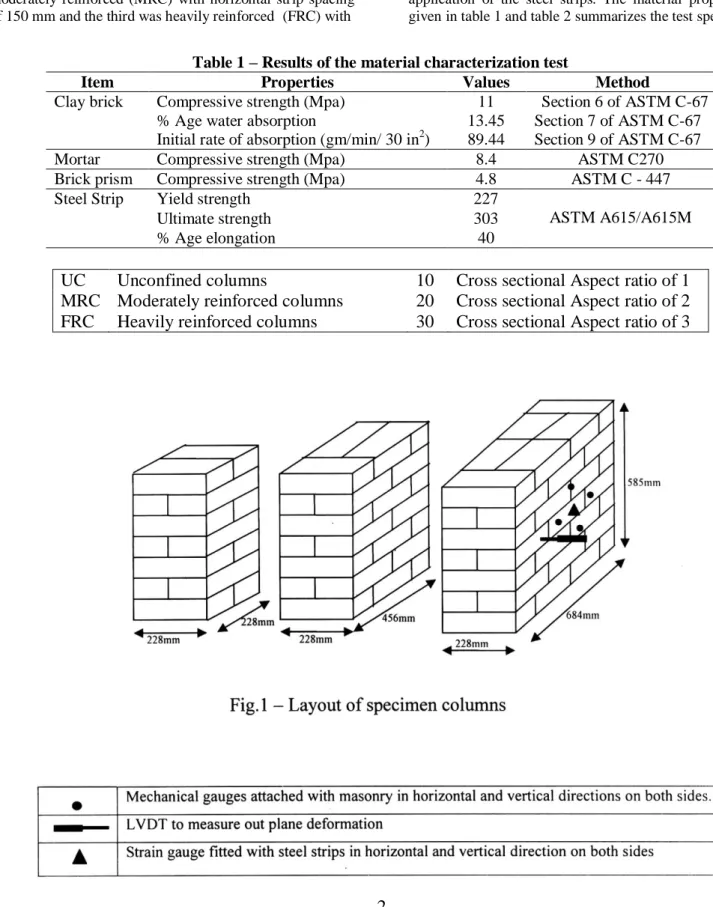
fix the steel strips into the column. The cross-sectional area of the specimens in first group was 228mm × 228mm, for second group 228mm × 456mm and 228mm × 684mm in the third group. Each model column comprised bricks placed in seven rows with six bed joints in between and mortar thickness was kept 10mm in general, as shown in Figure 1. The specimens were wrapped with steel strips with different spacing of horizontal strips and the ends of the strips were overlapped approximately 100mm. In each group, one column was unreinforced, second was moderately reinforced (MRC) with horizontal strip spacing of 150 mm and the third was heavily reinforced (FRC) with
horizontal spacing of strips equal to 75mm. The spacing of vertical strips in all the specimens was 228mm. Details about the columns in each series are given in Table 1. The configurations described above allow investigation of the role of various parameters in the effectiveness of steel application as a means of confining masonry; these parameters include the aspect ratio of the cross section and reinforcement ratio.The steel strips were anchored with the columns after curing the specimens for at least one month and testing started approximately two weeks after application of the steel strips. The material properties are given in table 1 and table 2 summarizes the test specimens
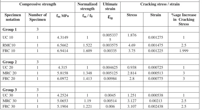
Table 1 – Results of the material characterization test
Item Properties Values Method
Clay brick Compressive strength (Mpa) 11 Section 6 of ASTM C-67 % Age water absorption 13.45 Section 7 of ASTM C-67 Initial rate of absorption (gm/min/ 30 in2) 89.44 Section 9 of ASTM C-67 Mortar Compressive strength (Mpa) 8.4 ASTM C270 Brick prism Compressive strength (Mpa) 4.8 ASTM C - 447 Steel Strip Yield strength 227
ASTM A615/A615M Ultimate strength 303
% Age elongation 40
UC
Unconfined columns
10
Cross sectional Aspect ratio of 1
MRC Moderately reinforced columns
20
Cross sectional Aspect ratio of 2
2.2 Test Setup & Instruments
The columns were tested under the Universal Testing Machine installed in the Civil Engineering Department, University of Engineering & Technology, Lahore, Pakistan. LVDTS, strain gauges and mechanical gauges were used to record the strain and deformation. Four strain gauges were used to record vertical and horizontal strains in strips on two faces of column, four mechanical gauges were used to measure vertical and horizontal strains in masonry and one LVDT was used to measure the out-of-plane deflection of the column as shown in figure 1.
3. Experimental Results
3.1 Stress-strain Behavior of Group 1
Figure 2 shows the stress versus strain both in the lateral and axial direction of the specimens. A negative sign
0 1 2 3 4 5 6 7 8
-0.006 -0.005 -0.004 -0.003 -0.002 -0.001 0 0.001 0.002 0.003 0.004 STRAIN
S
TRES
S
(
M
P
a)
"VER UC10" HOR UC10 VER MRC10 HOR MRC10 VER FRC10 HOR CFR10
Fig.2 – Stress-strain relationship of Group 1
indicates compressive axial strains while a positive sign indicates lateral dilation. The curves in almost all the cases are bilinear with no descending branch. The confinement has increased the ultimate stress but the ultimate lateral strain of confined columns is lesser than the unconfined columns.
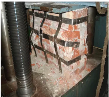
The increase in axial and lateral strain with increasing stress is less for confined columns. The ultimate stress of MRC10 and FRC10 is 1.52 and 1.61 times greater than UC10. Similarly the cracking stress and strain has also increased considerably. An increase of 2.5 and 2.0 in cracking stress was recorded for MRC10 and FRC10 respectively. The failure of UC10 was brittle with cracking starting at the top and traveled towards the bottom with increase in size causing crushing of bricks. The failure of both the confined columns was very similar. In confined columns after the formation of cracks through bricks/mortar, they became increasingly wide causing crushing of bricks and buckling of steel strips between the fasteners. Final failure occurred by pull out of bolts at overlap.
3.2 Stress-strain Behavior of Group 2
The stress-strain behavior observed in case of group 2 as shown in figure 3 was quite similar in case of all the three specimens. The confinement has increased the ultimate stress and strain of confined columns but increase in stress is less than group 1 with cross-sectional aspect ratio of 1. However, the increase in lateral and axial strain for confined columns is larger than the unconfined columns but corresponding stress was much higher. An increase of 1.35 and 1.41 times in ultimate stress was recorded for MRC20 and FRC20 as compared to UC20. Similarly the cracking stress has also increased by a factor of 3 in both the confined columns. The increase in ultimate stress is however less than Table 2 – Summary of test specimen
Compressive strength Normalized strength
Ultimate strain
Cracking stress / strain Specimen
notation
Number of Specimen
fmMPa fm / f0
ε
u Stress Strain %age Increase in CrackingStress Group 1 3
UC 10 1 4.3149 1 0.005337 5
1.876
0.001275 1 RMC10 1 6.5662 1.522 0.003575 4.69 0.001475 2.5 FRC 10 1 6.9414 1.609 0.00335 3.75 0.001225 1.999
Group 2 3
UC 20 1 4.315 1 0.004625 0.938 0.000725 1 MRC 20 1 5.8158 1.348 0.005125 2.814 0.000513 3 FRC 20 1 6.0972 1.413 0.00984 2.8 0.000775 3
Group 3 3
UC 30 1 4.2524 1 0.0045 1.251 0.000538 1 MRC 30 1 5.0653 1.19 0.00514 3.127 0.00213 2.5 FRC 30 1 5.1904 1.221 0.006 3.107 0.002438 2.5
the group 1 but cracking stress-strain have increased considerably. The failure pattern observed was quite similar to group 1.
0 1 2 3 4 5 6 7
- 0.01 - 0.008 - 0.006 - 0.004 - 0.002 0 0.002 0.004 0.006 0.008 0.01
ST RAIN
S
T
R
E
S
S
(
M
P
a
)
VER UC20 HOR UC20 VER MRC20 HOR MRC20 VER FRC20 HOR FRC20
Fig.3 – Stress-strain relationship of Group 2
3.3 Stress-strain Behavior of Group 3
The compression strength increase with respect to vertical-horizontal strain was quite similar to group 1&2 as shown in figure 4. An increase in ultimate stress and strain for confined columns was recorded but the increase in strength due to confinement was further reduced with increase in cross-sectional area as compared to group 1 & 2. An increase of 1.19 and 1.22 times in ultimate stress was recorded for MRC30 and FRC30 as compared to UC30. The cracking stress has increased by a factor of 2.5 in both the confined columns. The increase in ultimate stress is however less than the group 1 or 2 but cracking stress-strain have increased considerably. The failure pattern observed was quite similar to group 1and 2.
0 1 2 3 4 5 6 7
- 0.01 - 0.01 - 0.01 - 0 - 0 - 0 - 0 0 0 0 0 0 0.01 0.01 0.01
ST RAIN
S
T
R
E
S
S
(
M
P
a
)
VER UC30 HOR UC30 VER MRC30 HOR MRC30 VERT FRC30 HOR FRC30 Fig 4 – Stress-strain relationship of Group 3
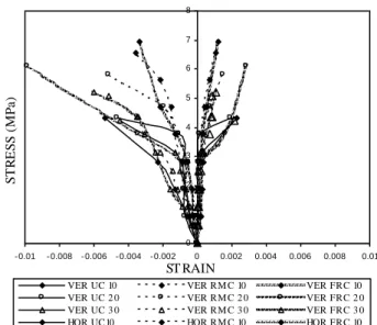
Figure 5 shows the stress-strain relationship of all the three groups. It is clear from the figure that the effectiveness of confinement reduces with increase in cross-sectional aspect ratio. Maximum increase of 61% was achieved for group 1 with aspect ratio of 1 and it reduces to 22% for group 3 with aspect ratio of 3. Figure 6 (a, b, c & d) shows the masonry columns at failure.
0 1 2 3 4 5 6 7 8
- 0.01 - 0.008 - 0.006 - 0.004 - 0.002 0 0.002 0.004 0.006 0.008 0.01
ST RAIN
S
T
R
E
S
S
(
M
P
a
)
VER UC 10 VER RM C 10 VER FRC 10
VER UC 2 0 VER RM C 2 0 VER FRC 2 0
VER UC 3 0 VER RM C 3 0 VER FRC 3 0
HOR UC10 HOR RM C 10 HOR FRC 10
HOR UC 2 0 HOR RM C 2 0 HOR FRC 2 0
HOR UC 3 0 HOR RM C 3 0 HOR FRC 3 0
Fig 5 – Stress-strain relationship of all Groups
Fig 6a –Heavily reinforced column-10 at failure
Fig 6c– Moderately reinforced colm30 at failure
Fig 6d – Moderately reinforced colm20 at failure
3.4 Stress-Strain Behavior of Steel Strips Stress-strain behavior of steel strip indicate that steel did not yield and was within its elastic limit. Very less axial strain values i.e maximum of 0.00095 in case of FRC30 were recorded for all the confined columns. The lesser values indicates that the strength gain was only due to confinement provided by the mesh arrangement of horizontal/vertical steel strips and its effectiveness reduces with increase in aspect ratio and failure occured once masonry got crushed. The maximum value of axial strain recorded was 0.00095 in case of FRC30 column, which indicate the higher contribution of steel in confinement to enhance the compressive strength of masonry. The strain in horizontal strips was observed to be further less than the strain in vertical strips. Max horizontal strain value recorded was 0.00027 in case of MRC30 which indicate that the contribution of horizontal strips in strength enhancement was further minimum. This fact is also evident from
percentage strength increase in moderately confined and fine confined columns. There is hardly any difference in strength gain for MRC and FRC columns. The stress-strain relationship in steel strips for all the groups are shown in figure 7 (a, b & c).
0 1 2 3 4 5 6 7 8
- 0.0004 - 0.0003 - 0.0002 - 0.0001 0 0.0001 0.0002 0.0003 0.0004
ST RAIN
S
T
R
E
S
S
(
M
P
a)
VER M RC10 VER FRC10
HOR M RC10 HOR FRC10
Fig 7a – Stress-strain relationship in steel of Group1
0 1 2 3 4 5 6 7 8
- 0.0006 - 0.0004 - 0.0002 0 0.0002 0.0004 0.0006
ST RAIN
S
T
R
E
S
S
(
M
P
a
)
VER M RC2 0 HOR M RC2 0
VER FRC2 0 HOR FRC2 0
Fig 7b – Stress-strain relationship in steel of Group2
0 1 2 3 4 5 6 7
- 0.002 - 0.0015 - 0.001 - 0.0005 0 0.0005 0.001 0.0015 0.002
ST RAIN
S
T
R
E
S
S
(
M
P
a
)
VER M RC3 0 VER FRC3 0
HOR M RC3 0 HOR FRC3 0
4. Discussion
This section discusses the behavior of the test specimens before and after strengthening. The discussion includes the following characteristics of the test specimens :(1) volumetric strains (2) axial-lateral strain relationship and (3) confining effect;
4.1 Volumetric strains
Figure 8 (a, b & c) shows the axial strain against the volumetric strain εv, which is given as follows:
v
A
2
L (1)where εA = axial strain, and εL = lateral strain. In the figure the negative value of volumetric strain indicates contraction while a positive volumetric strain indicates dilation. The figure shows that all the columns have compaction response with no dilation at all and during the whole test the volumetric strain was contraction. This is due to the linear response of the steel strips system leading to a continuously increasing confining pressure until rupture of the specimen. For unconfined columns in all the three groups there is contraction initially followed by recovery branch whereas for all the confined columns there is contraction without any recovery. The unconfined columns contracted initially due to compressive load but after the cracking the lateral strain increased considerably as compared to axial strain causing the expansion and final failure of columns. Whereas, the confined columns, the steel strips played their role in arresting the sudden increase of lateral strain as compared to axial strain causing strength enhancement and delaying the cracking stage. Maximum values of volumetric strain were recorded in case of group 3 and minimum was recorded for group 1.
4.2 Axial-lateral strain relationship
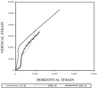
Figure 9 (a, b & c) indicates the axial strain-lateral strain relationship for masonry in which absolute values of compressive axial strains are taken. Approximately linear relationship exists between lateral strain and axial strain upto axial strain value of 0.1% to 0.2% in case of unconfined columns. After which lateral dilation of masonry increased at higher rate than the imposed axial strain due to accumulation of damage which caused the softening in the axial/lateral strain relationship. For the confined columns, the steel strips did not affect the axial/lateral strain relationship substantially, which means that the initial response of confined columns was quite similar to the unconfined columns as the lateral dilation of masonry is insignificant.
Then, there is a transition regime where the steel strips counteracting the masonry dilation effect thus the imposed axial strain increased at a higher rate than the lateral strain. Finally, with increase in the imposed axial strain, damage in masonry increased and accumulated leading to increase in the lateral dilation of the retrofitted specimens.
- 0.004 - 0.0035 - 0.003 - 0.0025 - 0.002 - 0.0015 - 0.001 - 0.0005 0
0 0.001 0.002 0.003 0.004 0.005 0.006
VERT ICAL ST RAIN
V
O
L
U
M
E
T
R
IC
S
T
R
A
IN
UC10 M RC10 FRC10
Fig 8a – Vertical strain vs volumetric strain Groups 1
-0.005 -0.0042 -0.0034 -0.0026 -0.0018 -0.001
-0.0002 0 0.002 0.004 0.006 0.008 0.01
VERTICAL STRAIN
V
O
LUM
ET
R
IC
S
TR
A
IN
UC20 MRC20 FRC
Fig 8b –Vertical strain vs volumetric strain Groups 2
-0.004 -0.0032 -0.0024 -0.0016 -0.0008 0
0 0.001 0.002 0.003 0.004 0.005 0.006 0.007
VERTICAL STRAIN
V
O
LU
M
ET
R
IC
STR
A
IN
UC30 MRC30 FRC30
0 0.001 0.002 0.003 0.004 0.005 0.006
0 0.001 0.002 0.003 0.004
HORIZONT AL ST RAIN
V
E
R
T
IC
A
L
S
T
R
A
IN
UC10 M RC10 FRC10
Fig 9a – Vertical vs lateral strain Groups1
0 0.002 0.004 0.006 0.008 0.01 0.012
0 0.0005 0.001 0.0015 0.002 0.0025 0.003 0.0035 0.004
HORIZONTAL STRAIN
V
ERTI
CA
L S
TRA
IN
UC20 MRC20 FRC20
Fig 9b – Vertical vs lateral strain Groups2
0 0.001 0.002 0.003 0.004 0.005 0.006 0.007
0 0.0008 0.0016 0.0024 0.0032 0.004
HORIZONT AL ST RAIN
V
E
R
T
IC
A
L
S
T
R
A
IN
UC3 0 M RC3 0 FRC3 0
Fig 9c – Vertical vs lateral strain Groups3
4.3 Confinement Effects
The passive confinement to masonry columns is provided by steel strips and for small axial load, the horizontal steel strips were approximately unstressed. Near an axial load of approximately 2.8 MPa, due to cracking in masonry the lateral strains increased and steel strips took the additional strain creating a confinement pressure. As shown in Figure 7, the axial strength and axial strain of the masonry specimens significantly improved due to contribution of steel strips to compression load and confinement effects. Following expression can be used to calculate the axial strength of a specimen:
P = Pm+Pc+Pst (2) P = Axial strength of the specimen
Pm = Strength due to masonry
Pc = Strength due to confinement
Pst = Vertical steel strips contribution to the axial
strength
The contribution of the steel strips to the axial load can be calculated as follows:
Pst = nεstEA (3)
n = total number of vertical steel strips (MRC/ FRC10=2, MRC/FRC20=4, MRC/FRC30=6)
st = Strain in the steel strips (MRC10=.000373,
FRC10=0.000313, RC20=0.000181, FRC20=0.00048, MRC30=0.0012, FRC30=0.00095; experimental values) E = Young’s Modulus of the steel strips
= 200000 MPa,
A = Cross sectional area of a steel strip = 45 x 1.3= 58.5 mm2
Substitute using these values in Eq. 3, the contribution of the steel strips to the axial load are 8.73kN, 7.3kN, 8.5kN, 22.5kN, 84.2kN and 66.7kN in the case of specimens MRC10, FRC10, MRC20, FRC20, MRC30 and FRC30 respectively. It clearly indicates that the contribution of vertical steel strips is increasing with increase in cross-sectional aspect ratio. The contribution of confining pressure provided by horizontal and vertical strips is determined by substituting values of Pm = Experimental value of axial
strength of the unconfined column, Pst values already
calculated by Eq. 3 and P = Experimental axial strength of the confined columns in Eq.3. The values of confining pressure are 109MPa, 129MPa, 148MPa, 165MPa, 44MPa, and 80.3MPa respectively for MRC10, FRC10, MRC20, FRC20, MRC30 and FRC30 respectively. The confining pressure significantly reduces with increase in cross sectional aspect ratio and it is in line with findings of Krevaikas and Triantafillou [13] and Farooq et.al [11].
Studies on confinement of rectangular masonry columns are very limited. Recently, Krevaikas and Triantafillou [13] have confined rectangular masonry columns FRP wrapping and have shown that the compressive strength enhancement is significantly reduces with increasing the cross sectional aspect ratio. The model proposed by Triantafillou is derived on the basis of the confinement mechanism for reinforced concrete which is approximately the same for masonry. They have used Mander’s model which was originally developed for steel-confined rectangular concrete cross section to determine the effective confinement pressure for the tested specimens. In Mander’s model, the relations between the compressive strength of confined concrete (f’cc) and unconfined concrete
(f’co) is as follows:
2
.
254
1
7
.
94
/
2
/
1
.
254
co l co l co
cc
f
f
f
f
f
f
(4)
Where, f’l is the effective confining lateral pressure. f’l
is obtained by substituting the values of f’cc (compressive
stress of confined columns) and f’co (compressive stress of
unconfined columns) in Eq. 4. The values of the confining pressure as a percentage of unconfined compressive strength, i.e., f’l/f’co for MRC10, FRC10, MRC20, FRC20,
MRC30 and FRC30 are 0.4, 0.48, 0.057, 0.07, 0.029 and 0.035 respectively. As expected, the effective confining pressure for FRC is slightly larger than MRC columns. In addition, the values are decreasing with increasing cross-sectional aspect ratio. However, these small effective confining pressures produced increase in compressive strength of columns by 52%, 61%, 35%, 41%, 19% and 22% in the case of MRC10, FRC10, MRC20, FRC20, MRC30 and FRC30 respectively.
5. CONCLUSIONS
The behavior of masonry columns before and after strengthening using steel strips is investigated and following conclusions are drawn:-
Steel strips are effective in increasing the compressive strength of masonry columns. The steel strips improved the compressive strengths by a factor up to 1.6, 1.4 and 1.2 for masonry columns with aspect ratio of 1, 2 and 3 respectively. In addition, an increase in stiffness of confined columns is reported as the cracking stress for confined columns improved significantly.
Although the ratio of confining pressure to unconfined stress was not very high, however, the axial strength improved significantly due to confinement. As expected, the effectiveness of confinement reduces with increase in cross-sectional aspect ratio.
The increase in lateral strain as compared to increase in axial strain was very less for confined columns causing
significant increase in strength. The steel strips did not contribute initially but after start of cracking they provided passive confining pressure. Thus the direct contribution of steel in strength enhancement was less and main enhancement in strength came from the confining effect of steel for columns with aspect ratio of 1, 2 & 3 and with increase in aspect ratio the confining pressure has reduced.
The unconfined columns showed contraction initially and then a recovery trend was observed in the relationship of volumetric strain-axial strain due to absence of confinement and crushing of masonry. Whereas, contraction was observed for all the confined columns.
6. ACKNOWLEDGEMENT
The authors are thankful to Higher Education Commission of Pakistan and University of Engineering & Technology, Lahore, Pakistan for extending their cooperation to complete this research work.
REFERENCES
[1] M. Ilyas and S. H. Farooq, (2005). “Collapse of a Building due to Percolation of Water from Rooftop in Old Lahore”, Proc., Seventh International Summer Symposium, Tokyo, Japan, 41-44.
[2] ElGawady M., Lestuzzi P., Badoux M (2004 a). A Review of Conventional Seismic Retrofitting Techniques for URM. In: Proceedings of 13th International Brick and Block Masonry Conference. Amsterdam, Paper No. 89.
[3] Ilyas M. and Farooq S. H., “Retrofitting techniques for masonry buildings damaged during 8th October earthquake”, Proceeding of The International Conference on Earthquake Engineering, Lahore, Pakistan, Sep 8-9, 2006.
[4] Tinazzi, D., Modena, C., and Nanni, A. (2000). “Strengthening of masonry assemblages with FRP rods and laminates.” Proc. Int. Meeting on Composite Materials, PLAST 2000, Advancing with Composites, Crivelli-Visconti, ed., Milan, Italy, 411–418.
[5] Tumialan, G., Huang, P.-C., Nanni, A., and Silva, P. (2001). “Strengthening of masonry walls by FRP structural repointing.” Proc., 5th Int. Conf. on Fibre Reinforced Plastics for Reinforced Concrete Structures, Thomas Telford, Cambridge, U.K., 1033– 1042.
[6] Schwegler, G. (1994), Bericht Nr. 229, PhD thesis, EMPA, Dübendorf, Germany.
[7] Triantafillou, T. C., and Fardis, M. N. ~1993!. “Advanced composites as strengthening materials of historic structures.” IABSE Symp. on Structural Preservation of the Architectural Heritage,
International Association for Bridge and Structural Engineering, Lisbon, Portugal, 541–548.
[8] Triantafillou, T. C., and Fardis, M. N. ~1997!. “Strengthening of historic masonry structures with composite materials.” Mater. Struct., 30, 486–486. [9] Mustafa Taghdi, Michel Bruneau and Murat Saatcioglu
(2000), “Seismic retrofitting of low rise masonry and concrete walls using steel strips”, J. of Structural Engineering, 1017-1025
[10] K. C. Voon and J. M. Ingham, “Design Expression for the In-Plane Shear Strength of Reinforced Concrete Masonry”, Journal of Structural Engineering © ASCE / May 2007, pp 706-713
[11] S.H.Farooq, Ilyas M. and Ghaffar A., “Technique of Strengthening Masonry Wall Panels using Steel Strips”, Asian Journal of Civil Engineering(Building and Housing) Iran, Vol. 7, No. 6, Pages 625-642, 2006
[12] S.H.Farooq, Ilyas M. and Ghaffar A., “Effect of Horizontal Reinforcement in Strengthening of Masonry Members”, Mehran University Research Journal of Engineering & Technology Pakistan, Vol. 27, No. 1, Pages 49-62, Jan, 2008
[13] Theofanis D. Krevaikas and Thanasis C. Triantafillou, “Masonry Confinement with Fiber Reinforced Polymers”, Journal of Composites for Construction © ASCE / March/April 2005, pp 128-135