Outdoor Unit
Dual System Kit
MULTI–SPLIT SYSTEM AIR CONDITIONER
Model No. Product Code No.
AER534QC 387007146
Model No. Product Code No.
DKR8585C 387025905
AER534QC
DKR8585C
(Option)
0.8180.234.0 03/2002
®
TECHNICAL & SERVICE MANUAL
AER534QC
I
Important!
Please Read Before Starting
This air conditioning system meets strict safety and operating standards. As the installer or service person, it is an important part of your job to install or service the system so it operates safely and efficiently.For safe installation and trouble-free operation, you must:
●Carefully read this instruction booklet before beginning.
●Follow each installation or repair step exactly as shown.
●Observe all local, state, and national electrical codes. ●Pay close attention to all warning and caution notices
given in this manual.
This symbol refers to a hazard or unsafe practice which can result in severe personal injury or death.
This symbol refers to a hazard or unsafe practice which can result in personal injury or product or property damage.
If Necessary, Get Help
These instructions are all you need for most installation sites and maintenance conditions. If you require help for a special problem, contact our sales/service outlet or your certified dealer for additional instructions.
In Case of Improper Installation
The manufacturer shall in no way be responsible for improper installation or maintenance service, including failure to follow the instructions in this document.
Special Precautions
When Wiring
ELECTRICAL SHOCK CAN CAUSE SEVERE PERSONAL INJURY OR DEATH. ONLY A QUALIFIED,
EXPERIENCED ELECTRICIAN SHOULD ATTEMPT TO WIRE THIS SYSTEM. • Do not supply power to the unit until all wiring and
tubing are completed or reconnected and checked. • Highly dangerous electrical voltages are used in this
system. Carefully refer to the wiring diagram and these instructions when wiring. Improper connections and inadequate grounding can cause accidental injury or death.
• Ground the unit following local electrical codes. • Connect all wiring tightly. Loose wiring may cause
overheating at connection points and a possible fire hazard.
WARNING CAUTION WARNING
When Transporting
Be careful when picking up and moving the indoor and outdoor units. Get a partner to help, and bend your knees when lifting to reduce strain on your back. Sharp edges or thin aluminum fins on the air conditioner can cut your fingers.
When Installing…
…In a Ceiling or WallMake sure the ceiling/wall is strong enough to hold the unit’s weight. It may be necessary to construct a strong wood or metal frame to provide added support.
…In a Room
Properly insulate any tubing run inside a room to prevent “sweating” that can cause dripping and water damage to walls and floors.
…In Moist or Uneven Locations
Use a raised concrete pad or concrete blocks to provide a solid, level foundation for the outdoor unit. This prevents water damage and abnormal vibration. …In an Area with High Winds
Securely anchor the outdoor unit down with bolts and a metal frame. Provide a suitable air baffle.
…In a Snowy Area (for Heat Pump-type Systems) Install the outdoor unit on a raised platform that is higher than drifting snow. Provide snow vents.
When Connecting Refrigerant Tubing
• Use the flare method for connecting tubing. • Apply refrigerant lubricant to the matching surfacesof the flare and union tubes before connecting them, then tighten the nut with a torque wrench for a leak-free connection.
• Check carefully for leaks before starting the test run.
When Servicing
• Turn the power off at the main power box (mains) before opening the unit to check or repair electrical parts and wiring.
• Keep your fingers and clothing away from any moving parts.
• Clean up the site after you finish, remembering to check that no metal scraps or bits of wiring have been left inside the unit being serviced.
Others
• Ventilate any enclosed areas when installing or testing the refrigeration system. Escaped refrigerant gas, on contact with fire or heat, can produce dangerously toxic gas.
• Confirm upon completing installation that no refrigerant gas is leaking. If escaped gas comes in contact with a stove, gas water heater, electric room heater or other heat source, it can produce
dangerously toxic gas.
Table of Contents
Page
UNIT COMBINATION IV
1 OPERATING RANGE
1
2 SPECIFICATIONS
2-1 Unit Specification
2
2-2 Major Component Specifications 4
2-3 Other Component Specifications 5
3 DIMENSIONAL DATA 7
4 REFRIGERANT FLOW DIAGRAM 9
5 ELECTRICAL DATA
5-1 Electrical Characteristic 11
5-2 Electric Wiring Diagrams 12
6 INSTALLATION INSTRUCTION
6-1 Installation Site Selection 15
6-2 Place and Space for Installation 16
6-3 Installation with Dual System Kit 17
6-4 Wiring Instruction 18
7 FUNCTION 20
8 TROUBLESHOOTING
8-1 Check before and after troubleshooting 21
8-2 Air Conditioner Does not operate 22
8-3 Some Parts of Air Conditioner does not operate 23
8-4 Air Conditioner operates, but abnormalities are observed 25
9 SPECIAL PRECAUTIONS WHEN SERVICING THE UNIT
9-1 Blue/green connector attachment for servicing 27
9-2 Refrigerant recovery 28
9-3 Service on outdoor unit 28
9-4 Evacuation using vacuum pump 28
9-5 Refrigerant charging 29
9-6 Reattaching green connectors for operation 30
10 REFRIGERANT R407C:SPECIAL PRECAUTION WHEN SERVICING THE UNIT
10-1 Characteristics of new refrigerant R407c 32
10-2 Checklist before servicing 32
10-3 Tools specially for R407c 33
10-4 For tubing installation procedures 33
10-5 In case of compressor malfunction 34
10-6 In case refrigerant is leaking 36
10-7 Charging additional refrigerant 38
10-8 Retro-fitting existing systems 38
11 ARRANGEMENT OF ELECTRICAL COMPONENTS 39
12 CHECKING ELECTRICAL COMPONENTS
12-1 Measurement of insulation resistance 41
12-2 Checking motor capacitor 42
IV
■
Unit Combination
Combine indoor and outdoor units only as listed below.
Indoor Unit
Outdoor Unit
A
B
C
Fig.1
Indoor Unit
Outdoor Unit
A
B
C1
C2
Fig.2
Dual System Kit
Symbol of Indoor Unit Outdoor Unit Dual System Kit Indoor Unit
(Option)
AER534QC
AWR609 A
AWR609 B Fig.1 Refer to
NON AWR518 C
AWR609 A
Fig.2
AWR609 B
DKR8585C AWR609 C1 AWR609 C2
1
1. OPERATING RANGE
Temperature Indoor Air Intake Temp. Outdoor Air Intake Temp.
Cooling Maximum 32°C D.B. / 23°C W.B. 43°C D.B. Minimum 19°C D.B. / 14°C W.B. 19°C D.B.
2
Symbol of indoor unit A , B : AWR609 C : AWR518
Power Source 220 – 240 V ~ 50 Hz
Cooling Max.Capacity kW 9.80
BTU/h 33800
Indoor unit(s) A + B C A + B + C
Capacity kW 5.50 4.3 9.8 BTU/h 19000 15000 33800 Voltage rating V 230
Available voltage range V 198 to 264
Running amperes A 10.9 9.5 19 Power input W 2350 2000 4050 Power factor % 94 92 93 C.O.P. W/W 2.4 2.2 2.4 Compressor locked rotor amperes A 45 / 46 / 48 41 / 43 / 45 86 / 89 / 93
Fan speed 2
Compressor Rotary (Hermetic)
Refrigerant / Amount charged at shipment g R407c / A + B : 1,300 C : 1,200
Refrigerant control Capillary tube
Operation sound dB-A 54
Refrigerant tubing connections Flare type Max. allowable tubing length at shipment m A + B : 15 C : 7.5 Refrigerant tube Narrow tube mm (in.) A , B , C : 6.35 (1/4) diameter Wide tube mm (in.) A , B : 9.52 (3/8) C : 12.7 (1/2)
Refrigerant tube kit Optional
Dual system kit Non
AER534QC
Unit dimensions Height mm 1,235
Width mm 940
Depth mm 340
Package dimensions Height mm 1,343
Width mm 1,036
Depth mm 421
Weight Net kg 108.0
Shipping kg 116.0
Shipping volume m3 0.59
Dimensions & Weight
Features
Electrical Rating
Performance
Outdoor Unit AER534QC
DATA SUBJECT TO CHANGE WITHOUT NOTICE.
Remarks: Rating conditions are:
Indoor air temperature 27°C D.B. / 19°C W.B. Outdoor air temperature 35°C D.B. / 24°C W.B.
2. SPECIFICATIONS
2-1. Unit Specifications
3
Symbol of indoor unit A , B , C1 , C2 :AWR609
Power Source 220 – 240 V ~ 50 Hz
Cooling Max.Capacity kW 10.5
BTU/h 36,200
Indoor unit(s) A + B C1 + C2 A + B + C1 + C2
Capacity kW 5.50 5.00 105 BTU/h 19000 17100 36200 Voltage rating V 230
Available voltage range V 198 to 264
Running amperes A 10.9 9.2 19 Power input W 2350 2000 4080 Power factor % 94 94 93 C.O.P. W/W 2.4 2.5 2.6 Compressor locked rotor amperes A 46 43 89
Fan speed 2
Compressor Rotary (Hermetic)
Refrigerant / Amount charged at shipment g R407c / A + B : 1,300 C1 + C2 : 1,200
Refrigerant control Capillary tube
Operation sound dB-A 54
Refrigerant tubing connections Flare type Max. allowable tubing length at shipment m A + B : 15 C1 + C2 : 15 Refrigerant tube Narrow tube mm (in.) A , B , C1 , C2 : 6.35 (1/4) diameter Wide tube mm (in.) A , B , C1 , C2 : 9.52 (3/8)
Refrigerant tube kit Optional
Dual system kit Optional (DKR8585C)
AER534QC DKR8585C
Unit dimensions Height mm 1,235 444
Width mm 940 213
Depth mm 340 118
Package dimensions Height mm 1,343 170
Width mm 1,036 340
Depth mm 421 528
Weight Net kg 108.0 5.0
Shipping kg 116.0 6.0
Shipping volume m3 0.59 0.031
Dimensions & Weight
Features
Electrical Rating
Performance
Outdoor Unit AER534QC with DKR8585C (Option)
DATA SUBJECT TO CHANGE WITHOUT NOTICE.
Remarks: Rating conditions are:
Indoor air temperature 27°C D.B. / 19°C W.B. Outdoor air temperature 35°C D.B. / 24°C W.B.
4
DATA SUBJECT TO CHANGE WITHOUT NOTICE. Symbol of indoor uni A, B : AWR609 C : AWR518 or C1, C2 : AWR609
Type Rotary (Hermetic) Rotary (Hermetic)
Compressor Model name ... Q'ty C – 2RN170H5W... 1 (CM1) C – 2RN150H5W ... 1 (CM2) Code No. 80807045E 80805045C Nominal output W 1700 1500 Compressor oil cc 750 750 Coil resistance (Ambient temp. 25°C) Ω C – R : 1.35 C – R : 1.42
C – S : 3.42 C – S : 4.12
Type Internal protector Internal protector
Overload relay ... Q'ty — —
Safety
Operating temp. Open °C 160 ± 5 170± 5
devices
Close °C 100 ± 11 105 ± 11
Operating amp.(Ambient temp. 25°C) Trip in 6 to 16 sec. at 35A Trip in 6 to 16 sec. at 40A Run capacitor ... Q'ty µF 40 35
VAC 450 450
Type Propeller
Q'ty ... Dia. mm 2 ... ø460
Fan motor model ... Q'ty KFC6 T - 9 1 C 5 P ... 1 (upper) KFC6 T - 9 K 5 P ... 1 (lower) No. of poles ... rpm (230V, High) 6 ...778 6 ... 778
Nominal output W 66 66
Coil resistance (Ambient temp. 20°C) Ω WHT – BRN :127.3 / WHT - Violet : 56.73 Violet--YEL : 15..04 / YEL - PNK: 7.23
Safety Type Internal protector Internal protector
devices Operating temp. Open °C 130 ± 8 130 ± 8
Close 79 ±15 79 ±15
Run capacitor µF 5.0 6.0
VAC 400 400
Coil Aluminum plate fin / Copper tube
Rows 1
Fin pitch mm 1.3
Face area m2
0.456 x 2
External Finish Acrylic baked-on enamel finish
Heat
Exch. Coil
Compressor
Fan & Fan Motor
Outdoor Unit AER534QC
5
2-3. Other Component Specifications
Outdoor Unit AER534QC
Relay (R1, RR2) MCS24A2F1
Coil rating AC 240V
Coil resistance kΩ(at 20°C) 15.5 ± 15%
Contact rating AC 250V, 5A
Power Relay (PR1,PR2) G7L-2A-TUB
Coil rating AC 220/230/240V, Single Phase 50Hz
Coil resistance Ω(at 23°C) 21 ± 15%
Contact rating AC 220V, 25A
Thermostat (Fan Speed Control) YTB-4U201F
Switching temp. °C high →LOW 24°C
low →HIGH 26°C ± 1.5
+ 1.5 – 0.5
Timer (T) H3Y-2
Rating AC 220V, 50/60Hz
Operating time 3 minutes
Solenoid Valve (SV) NEV-MOAJ503B0 (Coil), NEV202DXF (Valve)
Rating AC 240V, 50/60Hz
7/6W, 45/35mA Coil resistance kΩ(at 20°C) 1.15 ±7%
:
6 Dual System Kit DKR8585C
Relay (R1, R2) MY2-02-US-TS
Coil rating AC 240V
Coil resistance Ω(at 20°C) 650 ± 15%
Contact rating AC 240V, 4.4A
Solenoid Valve (SV) NEV-MOAJ503B0 (Coil), NEV202DXF (Valve)
Rating AC 240V, 50/60Hz
7/6W, 45/35mA Coil resistance kΩ(at 20°C) 1.15 ±7%
Timer (T) H3Y-2-0
Rating AC 200–230V, 50/60Hz
Operating time 3 minutes
7
Outdoor Unit AER534QC
Air intake
Air discharge
145
696
60
60
115
58
58
58
58
58
250
250
940 340
100
83
450
400
380
1235
660
170 110 130
A B
C
Wide tube service valve : ø9.52 (3/8") Narrow tube service valve : ø6.35 (1/4")
Wide tube service valve : ø9.52 (3/8") Narrow tube service valve : ø6.35 (1/4")
Wide tube service valve : ø12.7 (1/2") Narrow tube service valve : ø6.35 (1/4")
A B C
Unit : mm
3. DIMENSIONAL DATA
8
Dual System Kit DKR8585C
50
72
50
50
148 118
56
177 213
393 425 444
18 50
Wide tube service valve Unit C1 : ø9.52 (3/8") Narrow tube service valve Unit C1 : ø6.35 (1/4")
Wide tube service valve Unit C2 : ø9.52 (3/8") Narrow tube service valve Unit C2 : ø6.35 (1/4")
Charge port ø6.35 (1/4")
Wide tube service valve From Unit C : ø12.7 (1/2") Narrow tube service valve From Unit C : ø6.35 (1/4")
9
Evaporator
Indoor Unit C (AWR518)
Wide tube O.D. ø12.7mm (1/2 ") Capi box Narrow tube O.D. ø6.35mm (1/4 ")
SAP-MC3447G5
3 Indoor Unit's Combination
Wide tube service valve Narrow tube service valve
Capillary tube Outdoor Unit AER534QC Wide tube O.D. ø9.52mm (3/8 ") Condenser Compressor 2 Accumulator B Evaporator
Indoor Unit A (AWR609)
Strainer
A
A
B
Evaporator
Indoor Unit B (AWR609)
SVA SVB Narrow tube O.D. ø6.35mm (1/4 ") Compressor 1 Accumulator Strainer C C S S SVC S SVD S Capillary for liguid injection Capillary for liguid injection Outdoor Unit AER534QC
3 Indoor Unit's Combination
4.
REFRIGERANT FL
O
W DI
A
GRAM
1
0
SAP-MC3447G5
ATK-P344G5
4 Indoor Unit's Combination with Dual Syatem Kit
Wide tube service valve Narrow tube service valve
Capillary tube
Outdoor Unit (AER534QC)
Wide tube O.D. ø9.52mm (3/8 ") Condenser Compressor 2 Accumulator B Evaporator
Indoor Unit A (AWR609)
Strainer
A
A
B
Evaporator
Indoor Unit B (AWR609)
SVA SVB Narrow tube O.D. ø6.35mm (1/4 ") Compressor 1 Accumulator Strainer C C S S SVC S SVD S Capillary for liguid injection Capillary for liguid injection Wide tube O.D. ø9.52mm (3/8 ") SVC1 SVC2 S S Strainer Narrow tube O.D. ø6.35mm (1/4 ") Evaporator
Indoor Unit C1 (AWR609)
Evaporator
Indoor Unit C2
(AWR609) Dual System Kit
(DKR8585C) Check port Outdoor Unit AER534QC with DKR8585C
5. ELECTRICAL DATA
5-1. Electrical Characteristics
The values in the table below indicate the sum of indoor units which are in running condition.
11 NOTE
Rating Conditions: Indoor Air Temperature 27°C D.B. / 19°C W.B. Outdoor Air Temperature 35°C D.B.
Full Load Conditions: Indoor Air Temperature 32°C D.B. / 23°C W.B. Outdoor Air Temperature 43°C D.B.
Number of indoor unit 3 - Units 4 - Units
(A + B + C) (A + B + C1 + C2)
Rating Conditions Running amp. A 19.0 19.0
Power input kW 4.05 4.08 Full Load Conditions Running amp. A 22.1 23.0
Power input kW 4.77 4.97
Outdoor Unit AER534QC 230V Single phase 50 Hz
Outdoor Unit AER534QC
5-2. Electric Wiring Diagram
Outdoor Unit DKR8585C
14
6-1. Installation Site Selection
Maximum Allowable Tubing Length and Elevation Difference(H).
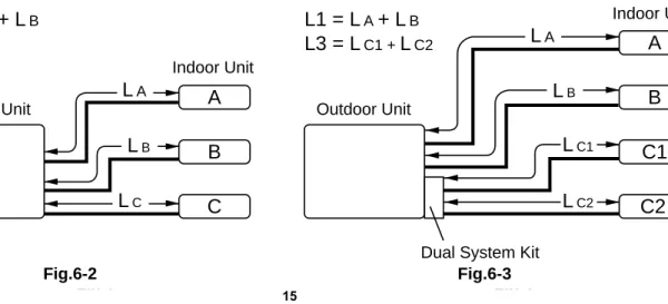
The Multi-Split System outdoor unit should be installed as close to the indoor units as possible. Maximum allowable length of the refrigerant tubing and elevation difference between outdoor and 3 indoor units are shown in Table 6-1 and Fig.6-2 while outdoor and 4 indoor units are shown in Table 6-2 and Fig.6-3.
15
Combination Max allowable tubing length at shipment.(m)
Limit of tubing length.(m)
Limit of elevation difference(H).
(m) Outdoor Unit Indoor Unit
AER534QC
A : AWR609
L1 15 25 7
B : AWR609
C : AWR518 L2 7.5 20 7 25
15
Required amount of additional refrigerant.*(g/m)
Combination Max allowable tubing length at shipment.(m)
Limit of tubing length.(m)
Limit of elevation difference(H).
(m) Outdoor Unit Indoor Unit
AWR534QC
with
DKR8585C
A.: AWR609
L1 15 25 7
B : AWR609 C1 : AWR609
L3 15 25 7
C2 : AWR609 15
15
Required amount of additional refrigerant.*(g/m)
6. INSTALLATION INSTRUCTIONS
INDOOR UNIT
OUTDOOR UNIT Less than elevation
difference (H) between the 2 units
Fig. 6-1
Table 6-1 3 indoor unit's combination
* If total tubing length becomes between "Max allowable tubing length" and "Limit of tubing length, charge additional refrigerant (R407c).
No additional change of compressor oil is necessary.
* If total tubing length becomes between "Max allowable tubing length" and "Limit of tubing length, charge additional refrigerant (R407c).
No additional change of compressor oil is necessary.
Table 6-2 4 indoor unit's combination with dual system kit
Indoor Unit
Outdoor Unit
Dual System Kit
A
B
C1
C2
Indoor Unit
Outdoor Unit
A
B
C
Fig 1 Fig 2
L
AL
BL
CL
C2L
C1L
BL
AL1 = L
A+ L
BL2 = L
CL1 = L
A+ L
BL3 = L
C1 +L
C26-2. Place and Space for Installation
●Choose a place as cool as possible. The place should
be well ventilated, and the intake air should not be hotter than the outside temperature.
(max. 45°C)
●Avoid the vicinity of heat sources, exhaust fans, etc.
(Fig. 6-4)
●Avoid direct sunlight, provide awning if necessary. ●Required space around the outdoor unit for free air
flow and servicing is given in Figs. 6-5a, and 6-5b.
The avoid the effects of humidity and ground moisture, the unit should be placed on concrete blocks or slab at least 10 cm high above ground level.
(Figs. 6-6 )
The unit must be level and be anchored securely to its base with anchor bolts or the like. An unsteady foundation will cause abnormal noise and vibration.
16
Outdoor unit Hot air
Heat source Exhaust fan
Fig 3 Fig.6-4
Air intake Min. 15 cm
Air discharge Min.
15 cm Min.
50 cm Valve side Min. 60 cm
Fig. 4 - B
Fig. 5 - A
Fig.6-6 AER534QC
Fig.6-5a
Min. 10cm
Air intake
Air intake
2 m 2 m
Ground
Obstacle
Obstacle above
Air discharge
Fig.6-5b Required space around the unit.
6-3. Installation with Dual System Kit
●The Dual System Kit splits the refrigerant circuit into two circuits, enabling two-room air conditioning with a
single outdoor unit.
●When using the Dual System Kit, two indoor units (four units in total) can be connected to a single outdoor unit.
(1) First, remove the capi box to install the Dual System Kit. (2) Connect the supplied connecting pipe to the Dual System Kit.
(3) Affix the Dual System Kit on the rear surface of the outdoor unit with the supplied tapping screws (4 pcs.) and connect the Dual System Kit to the service valves of the outdoor unit as shown below. (Figs. 6-8)
The tubing work for Indoor Units A and B have to be carried out after completion of Dual System Kit installation, air purging and a leak test.
NOTE
17
Outdoor Unit
Indoor Unit C1
Indoor Unit C2
Dual System Kit
Capi box
Dual System Kit
Connecting pipes
AER534QC
Fig.6-8 Fig.6-7
18
6-4. Wiring Instructions
6-4-1. General Precautions on Wiring
●Check the rated voltage on the unit's name platebefore wiring according to the wiring diagram.
●Provide a power outlet to be used exclusively for
each unit, with a power supply disconnect and a circuit breaker for overcurrent protection provided in the exclusive line.
●To prevent possible hazards due to insulation failure, the unit must be grounded.
●Each wire must be connected firmly.
●No wire should be allowed to touch refrigerant tubing, the compressor or any moving parts of fan motors.
Regulations on wire diameters differ according to national and local requirements.For field wiring regulations, please refer to the LOCAL ELECTRICAL CODES before starting, and carefully follow the regulations as you do the installation.
●Do not supply power to the system until all
wiring and refrigerant tubing connections are completed and checked.
●Wiring should only be done by an experienced,
qualified electrician.
●This appliance must be grounded.
Table 6-3 and 6-4 lists recommended wire lengths and diameters for power supply systems.
WARNING
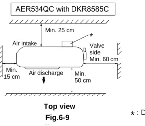
Top Space for Dual System Kit
When using the Dual System Kit, be sure to keep a separation of 25 cm as minimum between the air intake of the outdoor unit (rear surface) and wall or fence for maintenance work
(Fig.6-9).
*
: Dual System KitNOTE
Air intake
Min. 25 cm
Air discharge Min.
15 cm Min.
50 cm Valve side Min. 60 cm
Fig. 4 - B
*
AER534QC with DKR8585C
Fig.6-9 Top view
19
Model : AER534QC Power Supply Line Length (A)
Inter Line Length (B)
Inter Kit Line Length
(C) + (D) Fuse or Circuit Capacitor Cross-Sectional Aria (mm2) 3.5 mm2 2 mm2 2 mm2
Maximum Length (m) 14 m 20 m 20 m 30 A
5.5 mm2
22 m
Refer to the WIRING SYSTEM DIAGRAM for meaning of "A", "B", "C" and "D" in table 6-3.
Table 6-3
NOTE
Outdoor Unit : AER534QC
1 2 4 1 2 (B) (A) 1 2 4 5 6 8 1 2 4 Unit A Earth (ground) Disconnect swith (Field supply) Indoor unit Outdoor unit Power supply
220 – 240 V ~50Hz 3 L N Terminal 3P Terminal 8P
Terminal 5 P
Grounding Line 3
3 7 3 5 4 1 2 Unit B 3 L N 4 1 2 Unit C 3
Outdoor Unit : AER534QC Dual System Kit : DKR8585C
1 2 4 1 2 (C) 1 2 4 5 6 8 1 2 4 5 Unit A Disconnect switch (Field supply) Outdoor Unit 3 L N 1 2 4 Unit B 3 L N Terminal 3P Terminal 8P Terminal 5P
Grounding line 3
3
7
3 1
2
To unit C1
3 1 2 3 1 2
To unit C2
3 To out-door unit ATK-P3448G 4 4 4 (D) Indoor Units 5 Power supply 220 – 240 V
~50Hz (B) (A) 1 2 4 Unit C1 3 L N 1 2 4 Unit C2 3 L N
Unit A, B : AWR609
Unit C : AWR518
NOTE
Unit A, B : AWR609
Unit C1, C2 : AWR609
NOTE — Wiring System Diagram —
7. FUNCTION
Solenoid Valve Operation
●In the refrigeration circuit containing compressor 2 (CM2), the operation of the two solenoid valves (SVA and SVB) are synchronized and controlled by the thermo. ON signal of the indoor units.
●Opening both of these solenoid valves (SVA and SVB) makes the two indoor units (indoor unit A and B) operate.
Opening just one solenoid valve makes only one indoor unit run (either indoor unit A or B).
●3 minutes timer controlling the operation of compressor 2 (CM2), starts counting as soon as the thermo. ON signal is generated by indoor unit A or B.
●Compressor 2 (CM2) stops only under the condition when both indoor unit A and B have been stopped. ●Once the compressor stops, it will not start running again for at least 3 minutes even there has been an ON
signal from one of the indoor units.
●In order to save compressor power, solenoid valve C (SVC), which is used as a bypass valve, opens only when
either of indoor unit A or B is operating while it closes when both indoor unit A and B are operating.
20
Indoor unit A Solenoid valve A (SVA)
Solenoid valve B (SVB)
ON ON
Indoor unit B ON ON
Compressor 2 (CM2) ON
Solenoid valve C (SVC) OPEN
3 minutes 3 minutes 3 minutes
OPEN OPEN ON ON Indoor unit A ON Indoor unit A ON Indoor unit A OFF (Simultaneously) Indoor unit B ON Indoor unit B ON Indoor unit A OFF Indoor unit B OFF Indoor unit B OFF OPEN OPEN OPEN OPEN OPEN COND SVC SVA SVB CAPI CAPI CAPI LI CAPI CM2 Unit A Unit B Unit C
21
8. TROUBLESHOOTING
8-1. Check before and after troubleshooting.
8-1-1. Check power supply wiring.
●Check that power supply wires are correctly connected to terminals No. 1 and No. 2 on the 3P terminal plate in
the outdoor unit.
8-1-2. Check inter-unit wiring.
●Check that inter-unit wiring is correctly connected to the indoor units from the outdoor unit.
8-1-3. Check power supply.
●Check that voltage is in specified range (±10% of the rating). ●Check that power is being supplied.
8-1-4. Check lead wires and connectors.
●Check that coating of lead wires is not damaged.●Check that lead wires and connectors are firmly connected.
●Check that wiring is correct. WARNING
Hazardous voltage can cause ELECTRIC SHOCK or DEATH. Disconnect power or turn off circuit breaker before you start checking or servicing.
22
8-2. Air conditioner does not operate.
8-2-1. Circuit breaker trips (or fuse blows).
A. When the circuit breaker is set to ON, it is tripped soon. (Resetting is not possible.) ●There is a possibility of ground fault.
●Check insulation resistance.
If resistance value is 1MΩor less, insulation is defective (“NO”).
B. Circuit breaker trips in several minutes after turning the air conditioner on. ●There is a possibility of short circuit.
Measure insulation resistance of electrical parts in outdoor unit. NO
NO Set circuit breaker to OFF.
*
Measure insulation resistance of electrical parts in indoor unit. 1 Remove both power supply wires
and inter-unit wires from terminal plate in outdoor unit.
Measure insulation resistance of outdoor unit.
•
2 Remove inter-unit wires from terminal plate in indoor unit. Measure insulation resistance of indoor unit.
•
•
•
Insulation of outdoor unit is defective.
Insulation of indoor unit is defective.
Check capacity of circuit breaker. Capacity of circuit breaker is suitable.
Replace with suitable one (larger capacity). •
Measure resistance of compressor motor winding. (CM1, CM2) •
Measure resistance of outdoor fan motor winding. (FM)
•
23
8-2-2. Neither indoor nor outdoor unit runs.
Power is not supplied.8-2-3. Only outdoor unit does not run.
Check power relay in outdoor unit.Check connectors in outdoor unit.
8-3. Some part of air conditioner does not operate.
8-3-1. Only outdoor fan does not run.
NO Check power supply.
Power is being supplied to the outdoor unit. •
Power failure
Reset breaker.
Wait for recovery or contact power company. Circuit breaker
is tripped.
Measure coil resistance of power relay (PR1, PR2)
NO
Reattach GRN/GRN connectors. Are green/green connectors attached
together in outdoor unit?
Fan cannot be turned.
Check fan casing for foreign matter on inside. Check fan rotation.
Turn fan gently once or twice by hand.
•
Measure resistance of outdoor fan motor winding.
•
OK
•
Fan motor burnout or foreign matter in bearings.
Repair or replace. Remove foreign matter or repair.
Check fan motor capacitor.(C1 or C2) •
Refer to " 9-6 Reattaching green connectors for operation". NOTE
24
8-3-2. Only compressor does not run.
Check Timer in outdoor unit
Measure resistance of compressor motor winding. •
NO Check compressor motor
capacitor. •
YES
YES
YES Overload relay is working.
Refrigerant gas shortage. Charge refrigerant gas (R22). Temperature of compressor is
abnormally high.
Rotor may be locked up. (OLR 1 to 4) (C2,C3 or C3,C4)
Operate either indoor unit A or B.
Check to see if the lamp " PW " is on.
Check to see if the other lamp " UP " lights up as well.
Confirm that the timer dial has been set to " 3 min " as shown in figure right.
Replace the timer. YES
YES
NO
3 0
2 1
H3Y
min
25
8-4. Air conditioner operates, but abnormalities are observed.
8-4-1. Indoor unit operates, but there is no cooling.
Check solenoid valve in outdoor unit.
8-4-2. Poor cooling.
Measure coil resistance of solenoid valve (SVA , SVB)
Clean filter. Air filter is clogged.
Fan speed is set to LOW. •
NO
YES
Review cooling load estimate, if performance of air conditioner is normal.
•
Insulate both wide and narrow tubes
separately and then tape together.
Reduce cooling load or replace the air conditioner with larger capacity. Temperature
difference is small.
YES
Charge refrigerant gas (R407c). •
•
Temperature difference between suction and discharge air is
large enough (approx. 10 deg. or more).
Check for clogging of air filter. Measure temperature of suction and discharge air of air conditioner. Wide and narrow tubes between indoor unit and outdoor unit are insulated.
•
Possibility of gas shortage.
Set fan speed to either HIGH or MEDIUM. Check position of remote control unit.
Cool air from air conditioner reaches position directly.
YES Change position of
remote control unit. •
26
8-4-3. Excessive cooling.
Set temperature is suitable. •
Remote control unit is placed where it can detect room temperature properly.
• Change position of
remote control unit. NO
Set temperature to higher value using temperature setting buttons of the remote control unit.
Model : AER534QC
IMPORTANT!
For your personal safety, be sure to read
and understand the following precautions
before servicing.
●To avoid risk of injury when servicing the outdoor unit
(for instance, when replacing the compressor or repairing a refrigerant leak), follow the procedure below for the refrigerant circuits of unit A
and unit B.
— Procedure —
9-1. Blue/green connector
attachment for servicing
9-1-1. Confirm mains power is switched OFF, then disconnect the connectors (GRN/GRN) to separate A and B. Then connect A connector (GRN) with connector C (BLU). (Fig.9-1) 9-1-2. Provide a disconnect switch to the 3p terminal
plate. (Figs.9-2 and 9-3)
9-1-3. Turn the disconnect switch ON to supply power (single-phase, 220-240 V) to the outdoor unit. This makes it possible to force open two solenoid valves (SVA and SVB) in the refrigeration circuit. (Figs.9-2 and 9-3)
IMPORTANT!
The procedure given in "9-2" to "9-5" below must be carried out with the two solenoid valves SVA and SVB open.
27
9. SPECIAL PRECAUTIONS WHEN SERVICING THE UNIT
Injuries can occur from burns or inhalation of toxic gas if servicing is performed while refrigerant remains in the refrigeration circuit. This servicing includes disassembling brazed tubing connections and removing any
refrigeration parts or components. WARNING
Fig.1 Before
After
: CONNECTOR
4 5 8
GRN
BLU
• Condition at shipping • Condition for operation
Terminal plate
B A C
4 5 8
GRN BLU
• Condition at servicing (Procedure "9-2" ~ "9-5")
Terminal plate
C A B
9-2. Refrigerant recovery
9-2-1. Open the service valve to recover refrigerant into refrigerant recovery unit.
9-3. Service on outdoor unit
9-3-1. After making sure that the refrigerant in the circuit has been completely discharged, perform the required servicing, such as replacing the compressor or repairing refrigerant leaks. 9-3-2. Before going on to the next step, leak test all
joints where welding has been done.
Nitrogen gas is best when pressurizing the system for a leak test. However, if it is necessary to instead test with refrigerant gas, be sure to recover all gas into the refrigerant recovery unit after completing the leak test.
9-4. Evacuation using vacuum pump
9-4-1. Using a hex wrench, set the valve stems of boththe narrow and wide tube service valves as indicated in table below.
Refer to "■ Service Valve Construction "shown later
9-4-2. Connect the vacuum pump and a manifold valve as shown in either Fig.9-2 , depending upon the model. Confirm that all connections are correctly made.
In order to withstand negative suction pressure during evacuation, the manifold valve should be equipped with a Hi / Lo compound gauge with a
minimum scale reading of – 76
cmHg.
NOTE NOTE NOTE
28 Refrigerant released into the air contributes to destruction of our planet's ozone layer. You should always use the refrigerant recovery unit to help protect the environment.
CAUTION
Service Valve Valve Position
Unit A Narrow Position –c–
Wide
Unit B Narrow Position –a–
Wide
12 345 678
Terminal plate GRN BLU COND SVC SVA SVB CAPI CAPI CAPI LI CAPI CM2 Power Supply Disconnect switch (Field supply) Lo Hi Vacuum pump Manifold valve Unit A Unit B Unit C Vaccum gauge Fig.9-2
9-4-3. Install (first by hand-tightening, then securely with a wrench) flare nuts and bonnets at all service valves in the refrigeration circuit where evacuation will take place. This process is highly important
to completely evacuate the system.
9-4-4. Check that the blue/green connector is properly attached. (Fig.9-2 )
9-4-5. Turn the disconnect switch ON (if it has been OFF) to open the two solenoid valves (SVA and SVB). (Fig.9-2 )
9-4-6. With both the " Lo " and " Hi " knobs of the manifold valve open, run the vacuum pump. The operation time varies with the capacity of the pump. (Run the pump at least 30 minutes.) Evacuation is successful if the vacuum gauge reading remains – 75 cmHg or more for at least 10 seconds after closing both the " Lo " and " Hi " knobs of the manifold valve.
9-4-7. With the vacuum pump still running, turn both the narrow and wide service valves all the way in to close the valves (position -a-).
Then stop the pump.
9-4-8. After removing the vacuum hoses from the service valves, replace the flare nuts and bonnets on the valves. The refrigerant circuit is now ready for charging.
9-5. Refrigerant charging
9-5-1. After evacuation is completed, charge the circuit with the proper amount of refrigerant.
The proper amount of refrigerant is specified on the nameplate of the outdoor unit and in Section "2-1. Unit Specifications" in the service manual.
9-5-2. Use a hose to connect the narrow tube service valve to the liquid port of the charging cylinder.
(Fig.9-3)
9-5-3. Purge air from the hose. Do this by opening the charging cylinder valve, then slightly loosening the connection to the narrow tube service valve. Wait a few moments, then retighten the connection.
NOTE
29
12 345 678 Terminal plate GRN BLU Power Supply Disconnect switch (Field supply) Charging cylinder Open Unit A Unit B Unit C Hex wrench Fig.9-3 12 345 678
Terminal plate GRN BLU COND SVC SVA SVB CAPI CAPI CAPI LI CAPI CM2 Power Supply Disconnect switch (Field supply) Lo Hi Vacuum pump Manifold valve Unit A Unit B Unit C Vaccum gauge Fig.9-2 12 345 678
Terminal plate GRN BLU COND SVC SVA SVB CAPI CAPI CAPI LI CAPI CM2 Power Supply Disconnect switch (Field supply) Lo Hi Vacuum pump Manifold valve Unit A Unit B Unit C Vaccum gauge Fig.9-2
9-5-4. With a hex wrench, open the service valve little by little to let liquid refrigerant enter the circuit. (Fig.9-3)
●Write down the gradation levels on the charging
cylinder before and after the charging. This allows you to calculate the charging volume.
9-5-5. If it is not possible to completely charge the unit with the proper amount of refrigerant, you can do a additional charging after installing the units. At that time, refrigerant should be recharged in the liquid state a little at a time using the wide tube service port, and the air conditioner should be operating in COOLING mode during the entire charging process.
●Charging the unit with a large amount of
refrigerant at once may damage the compressor. Always charge the unit at a constant charging rate of about 100 g.
9-6. Reattaching green connectors
for operation
9-6-1. Turn off the power source.
9-6-2. Connect the two green connectors to each other as in the original state. (Fig.9-4)
NOTE Charging volume Gradation level before charging Gradation level after charging
=
–
NOTE 30 Remember to reattach the green connectors in the original position. Otherwise, the system will not operate correctly and damage may occur.CAUTION
: CONNECTOR
4 5 8
GRN
BLU
• Condition at shipping • Condition for operation
4 5 8
GRN BLU
• Condition at servicing (Procedure "9-2" ~ "9-5")
Terminal plate Terminal plate B A C A C B Before After Fig.9-4 12 345 678
Terminal plate GRN BLU Power Supply Disconnect switch (Field supply) Charging cylinder Open Unit A Unit B Unit C Hex wrench Fig.9-3
■
Service Valve Construction
●Valve Position
-a-The valve stems of both the wide and narrow tubes are turned all the way in. The unit is shipped from the factory in this position. (Fig.9-5a)
●Valve Position
-b-The valve stems of both the wide and narrow tubes are turned all the way out ("BACK SEAT" position). This is the normal operating position. (Fig.9-5b)
●Valve Position
-c-With the narrow tube valve kept at BACK SEAT, only the wide tube valve stem is turned to the halfway-down position. This position is used when refrigerant circuit evacuation is required from both narrow and wide tube valves at the same time. This position is also used when additional refrigerant charging is required in the field with both the indoor and outdoor units installed.(Fig.9-5c)
●Valve Position
-d-With the valve stem of the wide tube turned all the way in, only the narrow tube valve stem is turned to the halfway-down position. This position is used for refrigerant charging for only the outdoor unit. (Fig.9-5d).
31 When opening or closing the
service valve stem, use the supplied accessory hex wrench. Be sure to fully seat the wrench before turning the valve.
CAUTION
• Condition at Evacuation • Condition at Charging
in the Field.(-c-)
• Condition at Charging with Only Outdoor Unit (-d-) • Condition at Operation (-b-) • Condition at Shipping (-a-)
Valve cap Stem O-ring
Fig.9-5d Fig.9-5c Fig.9-5b Fig.9-5a
Wide Tube
Narrow Tube
Close
Hex wrench Open
10. REFRIGERANT R407C :
SPECIAL PRECAUTIONS WHEN SERVICING UNIT
10-1. Characteristics of new refrigerant R407C
10-1-1. What is new refrigerant R407C
R407C is a new refrigerant that contains three types of non-azeotropy-type mixed refrigerant which does not adversely affect the Earth's ozone layer. Its refrigeration capacity and energy efficiency are about the same level as the conventional refrigerant R22
10-1-2. Components (mixing proportions)
HFC32 (23%) / HFC125 (25%) / HFC134a (52%)
10-1-3. Characteristics
● Less toxic, more chemically stable refrigerant.
● Composition of refrigerant R407C changes whether it is in gaseous phase or liquid phase. Thus, when there is a
refrigerant leak the basic performance of the air conditioner may be degraded because of a change in composition of the remaining refrigerant. Therefore, do not add new refrigerant. Instead, recover the
remaining refrigerant with the refrigerant recovery unit. Then, after evacuation, totally recharge the specified amount of refrigerant with the new refrigerant at its normal mixed composition state (liquid phase).
● When refrigerant R407C is used, the composition will differ depending on whether it is in gaseous or liquid phase, and the basic performance of the air conditioner will be degraded if it is charged while the refrigerant is in gaseous state. Thus, always charge the refrigerant while it is in the liquid phase.
● Ether-type oil is used for the compressor oil for R407C-type units, which is
different from the mineral oil used for R22. Thus more attention to moisture prevention and faster replacement work compared with conventional models are required.
10-2. Checklist before servicing
●Tubing precautions
Refrigerant R407C is more easily affected by dust or moisture compared with R22, thus be sure to temporarily cover the ends of the tubing with caps or tape prior to installation.
●No addition of compressor oil for R407C
No additional charge of compressor oil is permitted.
●No use of refrigerant other than R407C
Never use a refrigerant other than R407C.
●If refrigerant R407C is exposed to fire
Through welding, etc., toxic gas may be released when R407C refrigerant is exposed to fire. Therefore, be sure to provide ample ventilation during installation work.
●Caution in case of R407C leak
Check for possible leak points with the special leak detector for R407C. If a leak occurs inside the room, immediately provide thorough ventilation.
CAUTION
10-3. Tools specifically for R407C
●
For servicing, use the following tools for R407C
● The above tools specifically for R407C must not be used for R22. Doing so will
cause malfunction of the unit.
● For the above vacuum pump (✽1, ✽2) and vacuum pump adapter (✽3) , those for
R22-type units can be used for R407C-type. However, they must be used exclusively for R407C and never alternately with R22.
10-4. For tubing installation procedures
● When the tubes are connected, always apply HAB oil on the flare portions to improve the sealing of tubing.
The following is the HAB oil generally used: Esso: ZERICE S32
For details on tubing installation procedures, refer to the installation manuals attached to the indoor unit and outdoor unit.
33
Tool Distinction Tool Name
• Gauge manifold • Charging hose • Gas leak detector • Refrigerant cylinder • Charging cylinder Tools specifically for R407C • Refrigerant recovery unit
• Vacuum pump with anti-reverse flow (✽1)
(Solenoid valve-installed type, which prevents oil from flowing back into the unit when the power is off, is recommended.)
• Vacuum pump (✽2) ... can be used if the following adapter is attached.
• Vacuum pump adapter (reverse-flow prevention adapter) (✽3).
(Solenoid valve-installed adapter attached to a conventional vacuum pump.) • Electronic scale for charging refrigerant
• Flare tool • Bender
Tools which can be commonly • Torque wrench
used for R22 and R407C • Cutter, Reamer
• Welding machine, nitrogen gas cylinder
CAUTION
10-5. In case of compressor malfunction
● Should the compressor malfunction, be sure to replace compressor as quickly as
possible.
● Use only the tools indicated exclusively for R407C. ➞ See "10-3. Tools specifically
for R407C".
10-5-1.Procedure for replacing compressor
(1) Recovering refrigerant
• Any remaining refrigerant inside the unit should not be released to the atmosphere, but recovered using the refrigerant recovery unit for R407C.
• Do not reuse the recovered refrigerant, since will contain impurities.
(2) Replacing compressor
• Soon after removing pinched pipes of both discharge and suction tubes of the new compressor, replace it quickly.
(3) Checking for sealing
• Use nitrogen gas for the pressurized gas, and never use a refrigerant other than R407C. Also do not use oxygen or any flammable gas.
(4) Evacuation
• Use a solenoid valve-installed vacuum pump so
that even if power is cut off in the middle of evacuation of air due to a power interruption, the valve will
prevent the pump oil from flowing back.
• The equipment may be damaged if moisture remains in the tubing, thus carry out the evacuation thoroughly. • When using a vacuum pump with exhaust air volume
more than 25L/min. and ultimate vacuum pressure rate of 0.05Torr:
34
CAUTION
(1). Recovering refrigerant OK
(2). Replacing compressor OK
(3). Checking for sealing OK
(4). Evacuation
OK
(5). Recharging
Standard time of evacuation
Length of tubing Less than 10 m More than 10 m
Valve
Valve
Single valve
Charge the liquid refrigerant with the cylinder in the up-side-down position.
Single valve (with siphon tube)
Charge with the cylinder in the normal position.
Liquid
Liquid
35
Configurations and characteristics of cylinders
Charging cylinder
Open Refrigerant
cylinder
Liquid
NO!
Fig. 2 Fig. 1
Fig.3
(5) Recharging
• Be sure to charge the specified amount of
refrigerant in liquid state using the service port of
wide tube service valve. The proper amount is listed on the unit's nameplate.
When the entire amount cannot be charged all at once, charge gradually while operating the unit in Cooling Operation.
● Never charge a large amount
of liquid refrigerant at once to the unit. This may cause damage to the compressor.
• When charged with a refrigerant cylinder, use the electronic scale for charging refrigerant. In this case, if the volume of refrigerant in the cylinder becomes less than 20% of the fully-charged amount, the composition of the refrigerant starts to change. Thus, do not use the refrigerant if the amount in the refrigerant cylinder is less than 20%.
Also, charge the minimum necessary amount to the cylinder before using it for charging the air
conditioning unit.
Example:
In case of charging refrigerant to a unit requiring 0.76Kg using a capacity of 10Kg-cylinder, the minimum necessary amount for the cylinder is:
0.76 + 10 x 0.20 = 2.76Kg
For the remaining refrigerant, refer to the instructions of the refrigerant manufacturer.
• If using a charging cylinder, transfer the specified amount of liquid refrigerant from the refrigerant cylinder to the charging cylinder.
Prepare an evacuated charging cylinder beforehand.
● To prevent the composition
of R407C from changing, never bleed the refrigerant gas into the atmosphere while transferring the refrigerant. (Fig. 3) Do not use the refrigerant if the amount in the charging cylinder is less than 20%.
CAUTION CAUTION
10-6. In case refrigerant is leaking
● Never attempt to charge additional refrigerant when refrigerant has been leaking
from the unit. Follow the procedure described below to locate points of leaks and carry out repairs, then recharge the refrigerant.
(1) Detecting Leaks
• Use the detector for R407C to locate refrigerant leak points.
(2) Recovering refrigerant
• Never release the gas to the atmosphere, recover residual refrigerant using the refrigerant recovery unit for R407C, instead.
• Do not reuse the recovered refrigerant because its composition will have been altered.
(3) Welding leaking points
• Confirm again that no residual refrigerant exists in the unit before starting welding.
• Weld securely using flux and wax for R407C. • Prevent oxide film from forming inside the tubes
utilizing substitution with nitrogen (N2) in the
refrigerant circuit of the unit. Leave ends of tubes open during welding.
(4) Checking for sealing
• Use nitrogen gas for the pressurized gas, and never use a refrigerant other than R407C. Also do not use oxygen or any flammable gas.
(5) Evacuation
• Use a solenoid valve-installed vacuum pump so
that even if power is cut off in the middle of evacuation of air due to a power interruption, the valve will prevent the pump oil from flowing back.
• The equipment may be damaged if moisture remains in the tubing, thus carry out the evacuation thoroughly. • When using a vacuum pump with exhaust air volume
more than 25L/min. and ultimate vacuum pressure rate of 0.05Torr:
36
(2). Recovering refrigerant OK
(3). Welding leaking points OK
(4). Checking for sealing OK
(5). Evacuation
OK
(6). Recharging (1). Detecting leaks
OK
CAUTION
Standard time of evacuation
Length of tubing Less than 10 m More than 10 m
(6) Recharging
• Be sure to charge the specified amount of
refrigerant in liquid state using the service port of
wide tube service valve. The proper amount is listed on the unit's nameplate.
When the entire amount cannot be charged all at once, charge gradually while operating the unit in Cooling Operation.
● Never charge a large amount
of liquid refrigerant at once to the unit. This may cause damage to the compressor.
• When charged with a refrigerant cylinder, use the electronic scale for charging refrigerant. In this case, if the volume of refrigerant in the cylinder becomes less than 20% of the fully-charged amount, the composition of the refrigerant starts to change. Thus, do not use the refrigerant if the amount in the refrigerant cylinder is less than 20%.
Also, charge the minimum necessary amount to the cylinder before using it for charging the air
conditioning unit.
Example:
In case of charging refrigerant to a unit requiring 0.76Kg using a capacity of 10Kg-cylinder, the minimum necessary amount for the cylinder is:
0.76 + 10 x 0.20 = 2.76Kg
For the remaining refrigerant, refer to the instructions of the refrigerant manufacturer.
• If using a charging cylinder, transfer the specified amount of liquid refrigerant from the refrigerant cylinder to the charging cylinder.
Prepare an evacuated charging cylinder beforehand.
● To prevent the composition
of R407C from changing, never bleed the refrigerant gas into the atmosphere while transferring the refrigerant. (Fig. 6) Do not use the refrigerant if the amount in the charging cylinder is less than 20%.
37
CAUTION
CAUTION
Valve
Valve
Single valve
Charge the liquid refrigerant with the cylinder in the up-side-down position.
Single valve (with siphon tube)
Charge with the cylinder in the normal position.
Liquid
Liquid
Fig. 4
Fig. 5 Configurations and characteristics of cylinders
Charging cylinder
Open Refrigerant
cylinder
Liquid
NO!
10-7. Charging additional refrigerant
10-7-1.When tubes are extended
• Observe the proper amount of refrigerant as stated in this service manual or the installation manual that came with the indoor unit. Charge additional refrigerant in liquid state.
● Never charge additional refrigerant if refrigerant is leaking from the unit. Follow
instructions given in "10-6. In case refrigerant is leaking" and completely carry out repairs. Only then should you recharge the refrigerant.
10-8. Retro-fitting existing systems
10-8-1 Use of existing units
• Never use new refrigerant R407C for existing units which use R22. This will cause the air conditioner to
operate improperly and may result in a hazardous condition.
10-8-2 Use of existing tubing
• If replacing an older unit that used refrigerant R22 with a R407C unit, do not use its existing tubing. Instead,
completely new tubing must be used.
38
39
Terminal Plate (8P) (To Indoor Unit A and B)
Terminal Plate (5P) (To either Indoor Unit C
or Dual System Kit)
Terminal Plate (3P) (To Power supply)
Compressor Motor Capacitor (C3)
Compressor Motor Capacitor (C4)
Timer (T)
Fan Motor Capacitor (C1) Fan Motor Capacitor (C2)
Power relay (PR1) Power relay (PR2) Relay (R4)
Relay (R3) Relay (R2) Relay (R1)
35µF 40µF
5µF 5µF Electric Parts
Terminal Plate
Outdoor Unit AER534QC
Heat exchenger coil
Parts Layout in Unit
Fan motor
Upper : KFC6T-91C5P (FM1), 5µF Lower : KFC6T-91C5P (FM2), 5µF
Compressor 2 (CM2)
To Indoor Unit A and B 80807045E, 1,700W, 40µF
Compressor 1 (CM1)
To Indoor Unit C or Dual System Kit. 80805045C, 1,500W, 35µF
11.ARRANGEMENT OF ELECTRICAL COMPONENTS
40
12
3
4
12
3
4
5
12
3
4
Terminal Plate
Electric Parts
Terminal Plate 1 (5P) (To Outdoor Unit) Terminal Plate 2 (4P)
(To Indoor Unit C1) Terminal Plate 3 (4P)
(To Indoor Unit C2)
Solenoid coil (SVC 1)
Solenoid coil (SVC 2) PCB Ass'y
41
12-1. Measurement of Insulation
Resistance
●The insulation is in good condition if the resistance
exceeds 1MΩ.
12-1-1. Power Supply Wires
Clamp the ground wire of the power supply wires with the lead clip of the insulation resistance tester and measure the resistance by placing a probe on either of the power wires. (Fig.12-1)
Then measure the resistance between the ground wire and the other power wire. (Fig.12-1)
12-1-2. Outdoor Unit
Clamp a metallic part of the unit with the lead clip of the insulation resistance tester and measure the resistance by placing a probe on each terminal screw where power supply lines are connected on the terminal plate. (Fig.12-2)
12-1-3. Measurement of Insulation
Resistance for Electrical Parts
Disconnect the lead wires of the desired electric part from terminal plate, capacitor, etc. Similarly disconnect the connector. Then measure the insulation resistance. (Figs.12-3 and 12-4)
Refer to Electric Wiring Diagram.
If the probe cannot enter the poles because the hole is too narrow then use a probe with a thinner pin.
Insulation tester Probe
Clip
Ground wire
Fig.12-1
Terminal plate
Copper tube or metallic part
Clip
Insulation tester
Probe
Fig.12-2
Copper tube or metallic part
Clip
Insulation tester
Probe
Fig.12-3
Clip
Insulation tester Probe
Metallic part
From fan motor, compressor and other parts
Fig.12-4
12. CHECKING ELECTRICAL COMPONENTS
42
12-2. Checking Motor Capacitor
Remove the lead wires from the capacitor terminals, and then place a probe on the capacitor terminals as shown in Fig.12-5. Observe the deflection of the pointer, setting the resistance measuring range of the multimeter to the maximum value.The capacitor is “good” if the pointer bounces to a great extent and then gradually returns to its original position.
The range of deflection and deflection time differ according to the capacity of the capacitor.
Multimeter
Ω
Compressor motor capacitor
Fan motor
Printed in italy
Via Varese, 90 - 21013 Gallarate - Va - Italy Tel. +39 0331 755111 - Fax +39 0331 776240