©2008
Case Study: ER24 SIP Gateway
Com.X SIP Gateways provide flexible, high
availability Telco &
multiple, legacy PBX’s
©2008 - 2013 Far South Networks (Pty) Ltd.
Case Study: ER24 SIP Gateway
Com.X SIP Gateways provide flexible, high
availability Telco & SIP interconnect for
multiple, legacy PBX’s
Version 1.0, 21 May 2013
Case Study: ER24 SIP Gateway
Com.X SIP Gateways provide flexible, high
SIP interconnect for
Version Date Description of Changes
1 21/05/13 Document creation
Document History Description of Changes
Table of Contents
1 Introduction ... 4
1.1 Overview ... 4
1.2 Background ... 4
2 SIP Gateway Requirements ... 5
2.1 Client Brief ... 5
2.2 ER24 PBX setup... 5
3 SIP Gateway platform architecture ... 6
3.1 IP Telephony solution ... 6
4 Solution design... 7
4.1.1 Network diagram ... 7
4.1.2 Equipment list ... 7
4.1.3 Network design ... 7
4.1.4 PRI configuration ... 8
4.1.5 Trunk configuration ... 8
4.2 Call flow requirements ... 8
4.2.1 Inbound ... 8
4.2.2 Outbound... 9
4.2.3 Notes on capacity ... 9
4.3 Installation instructions ... 9
4.3.1 Physical unit installation and earthing ... 9
4.3.2 Networking cabling ... 10
4.3.3 Primary rate ISDN ... 10
4.4 Configuration instructions ... 10
4.4.1 Accessing the systems... 10
4.4.2 Trunk configuration ... 10
4.4.3 Custom configurations (no-GUI) ... 11
4.5 Test report ... 11
4.5.1 Functional testing ... 11
1 Introduction
1.1 Overview
This document presents a case study of the design and
Gateway solution for ER24, Sunninghill, Gauteng, providing dynamic and flexible call routing between two on site, legacy PBX’s, ensuring high availability and failover to Telkom PRI and (Activate Telecoms) SIP services.
1.2 Background
Far South Networks was approached by Activate Telecoms (
telecoms.co.za) to develop a SIP Gateway solution to the unique requirements of
their client, ER24.
Activate Telecoms are a Johannesburg based reseller of Far South IP PBX and SIP Gateway platforms.
Introduction
This document presents a case study of the design and installation of a Com.X2 SIP Gateway solution for ER24, Sunninghill, Gauteng, providing dynamic and flexible call routing between two on site, legacy PBX’s, ensuring high availability and failover to Telkom PRI and (Activate Telecoms) SIP services.
Far South Networks was approached by Activate Telecoms (sales@activate
) to develop a SIP Gateway solution to the unique requirements of Johannesburg based reseller of Far South IP PBX and SIP
installation of a Com.X2 SIP Gateway solution for ER24, Sunninghill, Gauteng, providing dynamic and flexible call routing between two on site, legacy PBX’s, ensuring high availability and failover to
sales@activate-) to develop a SIP Gateway solution to the unique requirements of Johannesburg based reseller of Far South IP PBX and SIP
2 SIP Gateway Requirements
2.1 Client Brief
ER24 wanted transparent voice connectivity independent of whether there was a network failure from their Telco providers.
ER24 required SIP based connectivity across fibre as a primary out and inbound solution while maintaining Telkom PRI’s as redundancy should Activate Telecoms’ SIP network be unavailable.
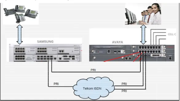
2.2 ER24 PBX setup
The existing ER24, Sunninghill, Gauteng, office telephony infrastructur two on-site, legacy PBX’s:
1. Emergency Call Centre PBX: Avaya PBX supporting 30 to 40 emergency call centre staff
2. General staff and administration: Samsung 7400 supporting 40 to 50 users
Figure 1 below presents a diagram of the telecoms in
Figure 1 – ER24 telephony infrastructure
Com.X Administrator Guide
SIP Gateway Requirements
ER24 wanted transparent voice connectivity independent of whether there was a network failure from their Telco providers.
ased connectivity across fibre as a primary out and inbound solution while maintaining Telkom PRI’s as redundancy should Activate Telecoms’ SIP network be unavailable.
ER24 PBX setup
The existing ER24, Sunninghill, Gauteng, office telephony infrastructur site, legacy PBX’s:
Emergency Call Centre PBX: Avaya PBX supporting 30 to 40 emergency call General staff and administration: Samsung 7400 supporting 40 to 50 users Figure 1 below presents a diagram of the telecoms infrastructure setup at ER24.
ER24 telephony infrastructure
Com.X Administrator Guide Page 5
ER24 wanted transparent voice connectivity independent of whether there was a
ased connectivity across fibre as a primary out and inbound solution while maintaining Telkom PRI’s as redundancy should Activate Telecoms’
The existing ER24, Sunninghill, Gauteng, office telephony infrastructure consisted of Emergency Call Centre PBX: Avaya PBX supporting 30 to 40 emergency call General staff and administration: Samsung 7400 supporting 40 to 50 users
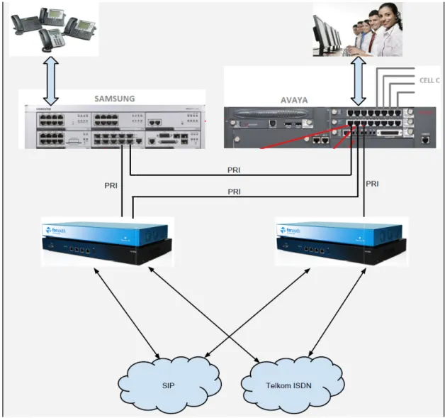
3 SIP Gateway platform architecture
3.1 IP Telephony solution
The proposed solution, as described in figure 2 below, consists of two Com.X2 SIP Gateway devices each with their own:
• SIP interconnect to Activate Telecom • Telkom PRI connection
In order to provide a flexible and dynamic, high availability interconnect between the existing PBX’s and the available Telecom and IP networks, the following load
balancing switch paths were provide
• Traffic failover between each Activate Telecom SIP service • Traffic failover between each Telkom PRI line
Figure 2 – Proposed, high
SIP Gateway platform architecture
IP Telephony solution
The proposed solution, as described in figure 2 below, consists of two Com.X2 SIP Gateway devices each with their own:
interconnect to Activate Telecom Telkom PRI connection
In order to provide a flexible and dynamic, high availability interconnect between the existing PBX’s and the available Telecom and IP networks, the following load
balancing switch paths were provided:
Traffic failover between each Activate Telecom SIP service Traffic failover between each Telkom PRI line
Proposed, high-level telephony architecture
The proposed solution, as described in figure 2 below, consists of two Com.X2 SIP
In order to provide a flexible and dynamic, high availability interconnect between the existing PBX’s and the available Telecom and IP networks, the following load
4 Solution design
4.1.1 Network diagramThe final platform network design diagram developed by shown in Figure 3.
Figure 3
4.1.2 Equipment list
The equipment list is indicated below:
• 1 x iTA-3P – codename 'Phoebe' • 1 x iTA-3P – codename 'Ganymede' • 1 x Com.X2 – codename
• 1 x Com.X2 – codename 'Ganymede' • Com.X2 and iTA power
• 10 x CAT-5 LAN cables
4.1.3 Network design
The network switch was partitioned into three partitions:
• Partition 1: ports 1
Com.X Administrator Guide
Solution design
Network diagramThe final platform network design diagram developed by Far South Networks is
Figure 3 – Network solution diagram
indicated below: codename 'Phoebe' codename 'Ganymede'
codename 'Phoebe' codename 'Ganymede' Com.X2 and iTA power
5 LAN cables
The network switch was partitioned into three partitions:
Partition 1: ports 1-8 reserved for the Phoebe iTA PRI ports
Com.X Administrator Guide Page 7
• Partition 2: ports 7 • Partition 3: ports 17
4.1.4 PRI configuration
The PRI within each iTA was configured as follows:
• phoebe PRI 1: Network mode, System timing, Drive clocking, E1 CRC
ETSI-ISDN, 16ms+NLP echo
• phoebe PRI 2: Network mode, System timing, Drive clocking, E1 CRC
ETSI-ISDN, 16ms+NLP echo cancellation
• phoebe PRI 3: Terminal mode, PRI priority 1 timing, E1 CRC
16ms+NLP echo cancellation
• ganymede PRI 1: Not configured (futu
• ganymede PRI 2: Network mode, System timing, Drive clocking, E1 CRC
ETSI-ISDN, 16ms+NLP echo cancellation
• ganymede PRI 3: Terminal mode, PRI priority 1 timing, E1 CRC
ISDN, 16ms+NLP echo cancellation
4.1.5 Trunk configuration
Two SIP trunks, one per Com.X2 were configured to carry traffic to and from the Activate Telecom SIP service provider (Neotel1 and Neotel2).
A SIP trunk was configured for load to provisioning inbound Activate Tele the Samsung system (lbToSamsung) A SIP trunk was configured for load
to outbound Traffic fail-over between the two An IAX trunk was configured for load
dedicated to outbound Telkom traffic fail
On each system, a Flexpath was created for receiving calls on each trunk interface, routed to the correct associated outbound route.
On each system, an outbound route was created for sending calls on each trunk interface.
On each system, a Flexpath was created for each load fail-over calls to the appropriate destination interface.
4.2 Call flow requirements
The following call flow requirements were agreed upon with was implemented in the Com.X
Partition 2: ports 7-16 reserved for the Ganymede iTA PRI ports Partition 3: ports 17 – 24 reserved for LAN connectivity
PRI configuration
each iTA was configured as follows:
phoebe PRI 1: Network mode, System timing, Drive clocking, E1 CRC ISDN, 16ms+NLP echo cancellation
phoebe PRI 2: Network mode, System timing, Drive clocking, E1 CRC ISDN, 16ms+NLP echo cancellation
phoebe PRI 3: Terminal mode, PRI priority 1 timing, E1 CRC-4, ETSI 16ms+NLP echo cancellation
ganymede PRI 1: Not configured (future PRI to Avaya)
ganymede PRI 2: Network mode, System timing, Drive clocking, E1 CRC ISDN, 16ms+NLP echo cancellation
ganymede PRI 3: Terminal mode, PRI priority 1 timing, E1 CRC ISDN, 16ms+NLP echo cancellation
Trunk configuration
trunks, one per Com.X2 were configured to carry traffic to and from the service provider (Neotel1 and Neotel2).
A SIP trunk was configured for load-balancing between the two Com.X2
Activate Telecom SIP traffic destined for the PRI connected to the Samsung system (lbToSamsung)
A SIP trunk was configured for load-balancing between the two Com.X2s, dedicated over between the two SIP services (lbSIP)
An IAX trunk was configured for load-balancing between the two Com.X2
dedicated to outbound Telkom traffic fail-over between the two Telkom PRIs (lbIAX) On each system, a Flexpath was created for receiving calls on each trunk interface, routed to the correct associated outbound route.
an outbound route was created for sending calls on each trunk On each system, a Flexpath was created for each load-balance trunk for routing of
over calls to the appropriate destination interface.
Call flow requirements
The following call flow requirements were agreed upon with Activate Telecom and implemented in the Com.X2 systems' configurations and tested:
the Ganymede iTA PRI ports
phoebe PRI 1: Network mode, System timing, Drive clocking, E1 CRC-4, phoebe PRI 2: Network mode, System timing, Drive clocking, E1 CRC-4,
4, ETSI-ISDN,
ganymede PRI 2: Network mode, System timing, Drive clocking, E1 CRC-4, ganymede PRI 3: Terminal mode, PRI priority 1 timing, E1 CRC-4,
ETSI-trunks, one per Com.X2 were configured to carry traffic to and from the balancing between the two Com.X2’s, dedicated
PRI connected to balancing between the two Com.X2s, dedicated
between the two Com.X2 Gateway’s, over between the two Telkom PRIs (lbIAX) On each system, a Flexpath was created for receiving calls on each trunk interface,
an outbound route was created for sending calls on each trunk balance trunk for routing of
• All calls inbound on
are routed to the Samsung 7400 via PRI 3 Ex ported Telkom
• All other calls inbound on
7400 via PRI 3 Ex ported Telkom(to be handled by the office)
• Congestion on trunks in the inbound direction results in busy 4.2.2 Outbound
• All calls originating from the Avaya on PRI 1 Ex Telkom are routed to Com.
1.1 via Neotel SIP 40
◦ Fail-over to Com.X 1.2 Neotel
◦ Fail-over to Com.X 1.1 TELKOM 1
◦ Fail-over to Com.X 1.2 TELKOM 2
• All calls originating from the Avaya on PRI 2 Ex Telkom are routed to Com.X
1.2 via Neotel1
◦ Fail-over to Com.X 1.1 Neotel
◦ Fail-over to Com.X 1.2 TELKOM 2
◦ Fail-over to Com.X 1.1 TELKOM 1
• All calls originating from the Samsung 7400 on PRI 3 Ex Telkom are routed to
Com.X 1.1 via Neotel
◦ Fail-over to Com.X 1.2 Neotel
◦ Fail-over to Com.X 1.1 TELKOM 1
◦ Fail-over to 4.2.3 Notes on capacity
If SIP trunk congestion is encountered on a Com.X and fail
capacity of the other Com.X SIP trunk being utilized, this in turn under load on the PRI trunks connected to the second Com.X might lead in th
turn trying to fail over to SIP on the first Com.X, resulting in fail
the second Com.X's TELKOM trunk. I.e. an indicator that more SIP capacity is required on a given Com.X would be that that Com.X's TELKOM trunk monitoring consistently shows increased traffic.
An indicator that the system's capacity as a whole is over when both Com.X TELKOM trunks consistently carry high load. Should SIP trunks or TELKOM trunks become unavailable, load
fail-over should continue in the manner described above until all trunk options have been exhausted.
Com.X 1.1 and 1.2 SIP trunks would be limited to match capacity using the "maxchannels" configuration field. If this should be configured on the Com.X SIP trunk as well.
4.3 Installation instructions
4.3.1 Physical unit installation and earthing
Please refer to the standard Com.X and iTA installation guides.
Com.X Administrator Guide
All calls inbound on Activate Telecom SIP with the Samsung 7400 DID range are routed to the Samsung 7400 via PRI 3 Ex ported Telkom
s inbound on Activate Telecom SIP are routed to the Samsung 7400 via PRI 3 Ex ported Telkom(to be handled by the office)
Congestion on trunks in the inbound direction results in busy
All calls originating from the Avaya on PRI 1 Ex Telkom are routed to Com. 1.1 via Neotel SIP 40
over to Com.X 1.2 Neotel1 over to Com.X 1.1 TELKOM 1 over to Com.X 1.2 TELKOM 2
All calls originating from the Avaya on PRI 2 Ex Telkom are routed to Com.X over to Com.X 1.1 Neotel2
over to Com.X 1.2 TELKOM 2 over to Com.X 1.1 TELKOM 1
All calls originating from the Samsung 7400 on PRI 3 Ex Telkom are routed to Com.X 1.1 via Neotel1
over to Com.X 1.2 Neotel1 over to Com.X 1.1 TELKOM 1 over to Com.X 1.2 TELKOM 2 Notes on capacity
If SIP trunk congestion is encountered on a Com.X and fail-over results in capacity of the other Com.X SIP trunk being utilized, this in turn under load on the PRI trunks connected to the second Com.X might lead in the second Com.X in turn trying to fail over to SIP on the first Com.X, resulting in fail-over to
the second Com.X's TELKOM trunk. I.e. an indicator that more SIP capacity is required on a given Com.X would be that that Com.X's TELKOM trunk monitoring
nsistently shows increased traffic.
An indicator that the system's capacity as a whole is over-utilized would be when both Com.X TELKOM trunks consistently carry high load.
Should SIP trunks or TELKOM trunks become unavailable, load-balance and er should continue in the manner described above until all trunk options
Com.X 1.1 and 1.2 SIP trunks would be limited to match Activate Telecom
using the "maxchannels" configuration field. If SIP capacity is increased, this should be configured on the Com.X SIP trunk as well.
Installation instructions
Physical unit installation and earthing
the standard Com.X and iTA installation guides.
Com.X Administrator Guide Page 9 SIP with the Samsung 7400 DID range
SIP are routed to the Samsung
All calls originating from the Avaya on PRI 1 Ex Telkom are routed to Com.X
All calls originating from the Avaya on PRI 2 Ex Telkom are routed to Com.X
All calls originating from the Samsung 7400 on PRI 3 Ex Telkom are routed to
over results in capacity of the other Com.X SIP trunk being utilized, this in turn under load on
e second Com.X in over to
the second Com.X's TELKOM trunk. I.e. an indicator that more SIP capacity is required on a given Com.X would be that that Com.X's TELKOM trunk monitoring
utilized would be
balance and er should continue in the manner described above until all trunk options
Activate Telecom SIP trunk capacity is increased,
4.3.2 Networking cabling
• Connect the 3x phoebe iTA LAN ports to the first bloc
Tenda TEH1226G switch (ports 2,4,6)
• Connect the 2x ganymede iTA LAN ports to the first block of 8 ports on the
Tenda TEH1226G switch (ports 12,14)
• Connect the phoebe X2's LAN 1 (the LAN port closest to the X2 power
supply) to the third
• Connect the ganymede X2's LAN 1 to the third block of 8 ports on the Tenda
TEH1226G switch (port 20)
• Connect the switch port 22 to the local LAN switch at the client site. • Connect the phoebe X2's LAN
• Connect the ganymede X2's LAN 2 to block 2 on the switch (port 16) • Connect the phoebe X2's LAN 3 to the Neotel router (right
• Connect the ganymede X2's LAN 3 to the Neotel router (right
• Connect the ganymede X2's LAN 4 to the phoebe X2's LAN 4 (LAN4 is just
left of LAN 3) 4.3.3 Primary rate ISDN
• Connect the phoebe iTA's PRI port 1 to Avaya • Connect the phoebe iTA's PRI port 2 to Samsung • Connect the phoebe iTA's PRI port 3 to Telkom • Leave ganymede's iTA port 1 open (future PRI) • Connect the ganymede iTA's PRI port 2 to Avaya • Connect the ganymede iTA's PRI port 3 to Telkom
4.4 Configuration instructions
4.4.1 Accessing the systems
Both X2s can be accessed via serial console, or via their default IPs on
Note that moving from the X2 power socket to the right, the LAN ports are numbered as follows: 1, 2, 4, 3.
Note also that LAN 1 (eth0) is configured as a DHCP client by default. Note also that LAN 4 (eth3) is reserved for load
Com.X2s and its configuration is specific and not the default. 4.4.2 Trunk configuration
(Mandatory) On both X2 systems, configure the Activate Telecom VPN as appropriate on LAN3.
Networking cabling
Connect the 3x phoebe iTA LAN ports to the first block of 8 ports on the Tenda TEH1226G switch (ports 2,4,6)
Connect the 2x ganymede iTA LAN ports to the first block of 8 ports on the Tenda TEH1226G switch (ports 12,14)
Connect the phoebe X2's LAN 1 (the LAN port closest to the X2 power supply) to the third block of 8 ports on the Tenda TEH1226G switch (port 18) Connect the ganymede X2's LAN 1 to the third block of 8 ports on the Tenda TEH1226G switch (port 20)
Connect the switch port 22 to the local LAN switch at the client site. Connect the phoebe X2's LAN 2 to block 1 on the switch (port 8) Connect the ganymede X2's LAN 2 to block 2 on the switch (port 16) Connect the phoebe X2's LAN 3 to the Neotel router (right-most LAN port) Connect the ganymede X2's LAN 3 to the Neotel router (right-most LAN port) Connect the ganymede X2's LAN 4 to the phoebe X2's LAN 4 (LAN4 is just
Primary rate ISDN
Connect the phoebe iTA's PRI port 1 to Avaya Connect the phoebe iTA's PRI port 2 to Samsung Connect the phoebe iTA's PRI port 3 to Telkom
ganymede's iTA port 1 open (future PRI) Connect the ganymede iTA's PRI port 2 to Avaya Connect the ganymede iTA's PRI port 3 to Telkom
Configuration instructions
Accessing the systems
Both X2s can be accessed via serial console, or via their default IPs on
Note that moving from the X2 power socket to the right, the LAN ports are numbered Note also that LAN 1 (eth0) is configured as a DHCP client by default.
Note also that LAN 4 (eth3) is reserved for load-balance connectivity between the Com.X2s and its configuration is specific and not the default.
Trunk configuration
(Mandatory) On both X2 systems, configure the Activate Telecom VPN as k of 8 ports on the Connect the 2x ganymede iTA LAN ports to the first block of 8 ports on the Connect the phoebe X2's LAN 1 (the LAN port closest to the X2 power
block of 8 ports on the Tenda TEH1226G switch (port 18) Connect the ganymede X2's LAN 1 to the third block of 8 ports on the Tenda Connect the switch port 22 to the local LAN switch at the client site.
2 to block 1 on the switch (port 8) Connect the ganymede X2's LAN 2 to block 2 on the switch (port 16)
most LAN port) most LAN port) Connect the ganymede X2's LAN 4 to the phoebe X2's LAN 4 (LAN4 is just
Both X2s can be accessed via serial console, or via their default IPs on the interfaces Note that moving from the X2 power socket to the right, the LAN ports are numbered
nectivity between the
(Optional) On both X2 systems, configure LAN1 with static IPs on the client's LAN (or determine the DHCP allocated IPs)
4.4.3 Custom configurations (no In /etc/asterisk/extensions_comma.conf ca
20 to facilitate trunk fail-over on PRIs where the Com.X2 plays the network role.
4.5 Test report
4.5.1 Functional testing
• The following functional tests were successfully performed (please refer to
Figure 3):
• Calls inbound on TE
• Calls inbound on TELKOM 2 routed to the Avaya via PRI Ex 2 Telkom
• Calls inbound on Com.X 1.1 Neotel SIP routed to the Samsung 7400 via PRI
3 Ex ported Telkom
• Calls inbound on Com.X 1.2 Neotel SIP routed to the
3 Ex ported Telkom via load
• Congestion on TELKOM 1 trunks in the inbound direction results in busy • Congestion on TELKOM 2 trunks in the inbound direction results in busy • Congestion on Neotel 1 in the inbound direction re
• Congestion on Neotel 2 in the inbound direction results in busy
• Calls originating from the Avaya on PRI 1 Ex Telkom routed to Com.X 1.1 via
Neotel SIP 40
o Fail-over to Com.X 1.2 Neotel SIP 30 o Fail-over to Com.X 1.1 TELKOM 1 o Fail-over to Com.X
• Calls originating from the Avaya on PRI 2 Ex Telkom are routed to Com.X 1.2
via Neotel SIP 30
o Fail-over to Com.X 1.1 Neotel SIP 40 o Fail-over to Com.X 1.2 TELKOM 2 o Fail-over to Com.X 1.1 TELKOM 1
• Calls originating from the Samsung 7400 on PRI 3
Com.X 1.1 via Neotel SIP 40
o Fail-over to Com.X 1.2 Neotel SIP 30 o Fail-over to Com.X 1.1 TELKOM 1 o Fail-over to Com.X 1.2 TELKOM 2
• PRI trunk disconnection fail
• Neotel trunk maxchannels capacity fail
4.5.2 Performance testing
Successfully placed > 82,000 calls over a 15 hour period at a rate of 1.5 calls / second.
Com.X Administrator Guide
(Optional) On both X2 systems, configure LAN1 with static IPs on the client's LAN (or determine the DHCP allocated IPs)
Custom configurations (no-GUI)
In /etc/asterisk/extensions_comma.conf cause code 27 was mapped to cause code over on PRIs where the Com.X2 plays the network role.
Functional testing
The following functional tests were successfully performed (please refer to Calls inbound on TELKOM 1 routed to the Avaya via PRI Ex 1 Telkom Calls inbound on TELKOM 2 routed to the Avaya via PRI Ex 2 Telkom
Calls inbound on Com.X 1.1 Neotel SIP routed to the Samsung 7400 via PRI 3 Ex ported Telkom
Calls inbound on Com.X 1.2 Neotel SIP routed to the Samsung 7400 via PRI 3 Ex ported Telkom via load-balance trunk
Congestion on TELKOM 1 trunks in the inbound direction results in busy Congestion on TELKOM 2 trunks in the inbound direction results in busy Congestion on Neotel 1 in the inbound direction results in busy
Congestion on Neotel 2 in the inbound direction results in busy
Calls originating from the Avaya on PRI 1 Ex Telkom routed to Com.X 1.1 via over to Com.X 1.2 Neotel SIP 30
over to Com.X 1.1 TELKOM 1 over to Com.X 1.2 TELKOM 2
Calls originating from the Avaya on PRI 2 Ex Telkom are routed to Com.X 1.2 over to Com.X 1.1 Neotel SIP 40
over to Com.X 1.2 TELKOM 2 over to Com.X 1.1 TELKOM 1
Calls originating from the Samsung 7400 on PRI 3 Ex Telkom are routed to Com.X 1.1 via Neotel SIP 40
over to Com.X 1.2 Neotel SIP 30 over to Com.X 1.1 TELKOM 1 over to Com.X 1.2 TELKOM 2
PRI trunk disconnection fail-over tested on all trunks
Neotel trunk maxchannels capacity fail-over on both Neotel trunks
Performance testing
Successfully placed > 82,000 calls over a 15 hour period at a rate of 1.5 calls /
Com.X Administrator Guide Page 11 (Optional) On both X2 systems, configure LAN1 with static IPs on the client's LAN (or
use code 27 was mapped to cause code over on PRIs where the Com.X2 plays the network role.
The following functional tests were successfully performed (please refer to LKOM 1 routed to the Avaya via PRI Ex 1 Telkom Calls inbound on TELKOM 2 routed to the Avaya via PRI Ex 2 Telkom Calls inbound on Com.X 1.1 Neotel SIP routed to the Samsung 7400 via PRI
Samsung 7400 via PRI Congestion on TELKOM 1 trunks in the inbound direction results in busy Congestion on TELKOM 2 trunks in the inbound direction results in busy
sults in busy Congestion on Neotel 2 in the inbound direction results in busy
Calls originating from the Avaya on PRI 1 Ex Telkom routed to Com.X 1.1 via
Calls originating from the Avaya on PRI 2 Ex Telkom are routed to Com.X 1.2
Ex Telkom are routed to
both Neotel trunks