Shape and Size Specific:
Fabrication, Characterization, and Application of Highly Tailored Biocompatible Hydrogel Particles for Use in Materials and Biomedical Settings
Kevin Patrick Herlihy
A dissertation submitted to the faculty of the University of North Carolina at Chapel Hill in partial fulfillment of the requirements for the degree of Doctor of Philosophy in the
Department of Chemistry (Polymer and Materials).
Chapel Hill 2009
Approved by
Joseph DeSimone
Valerie Ashby
Marcey Waters
Michael Rubenstein
Abstract Kevin Patrick Herlihy Shape and Size Specific:
Fabrication, Characterization, and Application of Highly Tailored Biocompatible Hydrogel Particles for Use in Materials and Biomedical Settings
(Under the direction of Joseph M. DeSimone)
This work details the method development of a bench top process designed to fabricate highly defined particles of uniform shape and size. In this method, perfluorinated elastomeric molds were patterned off of etched silicon wafers and other substrates. These molds were then filled with a pre-particle solution that was subsequently solidified by UV photoradical initiated polymerization. Particle harvesting by physical agitation and a variety of sacrificial adhesive layers was examined. Purification of particles was also explored using multiple techniques including: centrifugation, dialysis, and a variety of filtration techniques. Regioselective chemical and metallic surface functionalization was demonstrated. Direct particle analysis was performed using microscopic techniques and indirect analysis of particle loading and surface chemistry was performed using spectrophotometric, fluorescence, and mass spectrometry techniques.
To my cheerleader, nurse, wife, and bff.
To my parents.
The author would first like to thank Janine Nunes with whom I coauthored two manuscripts. Second, it is important to acknowledge the countless troubleshooting / brainstorming sessions that Elizabeth Enlow and I had. Third, Timothy Merkel deserves recognition and acknowledgement for his help in particle fabrication, his level headedness under pressure, and for helping me on the long nights spent during the animal studies as I dove headfirst into the unknown realm of radiochemistry. In addition the author would like to thank the army of scientists that helped him along the way: Curtis Bergquist for help with early particle design; Dr. Dorian Canelas for useful discussions on science and coauthoring a review on nanotherapeutics and imaging agents; Benjamin Evans and Lamar Mair of Prof. Richard Superfine’s Lab for helpful discussions on magneto-polymer composites; Briana Carstens of Prof. Richard Superfine’s lab for the vibrating magnetometry work; Dr. Wallace Ambrose and Amar Kumbhar of Chapel Hill Nanofabrication Labs for technical TEM assistance; Dr. C. Robert Bagnell for confocal microscopy assistance; Jeremy Niskala of Prof. Wei You’s lab for metal evaporation assistance; Carlos Villas and Prof. David Scheinberg of Memorial Sloan Kettering Cancer Center; Prof. Hong Yuan, Prof. Hongyu An, and Dr. Bryan Yoder of the Biomedical Research and Imaging Center of UNC Chapel Hill for help with small animal imaging; Dr. Gary Bordanero, Dr. Robert Ilic, and Dr. Meredith Metzler of the Cornell Nanofabrication Facility who were very helpful in the fabrication of silicon wafers with 2 x 2 x 1 µm3, 2 x 2 x 4 µm3, 2 x 2 x 6 µm3 rectangular features, and 10 x
features; Liquidia Technologies, Inc. for Fluorocur® and 80 x 360 nm and 80 x 2000 nm patterned PFPE molds; This work was supported by the STC program of the National
Science Foundation (CHE-9876674), National Institutes of Health Carolina Cancer Center
for Nanotechnology (5-U54-CA119373-02), and DARPA (07-4627). Finally, the author
Table of Contents Section 1: Particle Fabrication Methods Using the Particle
Replication In Non-wetting Template (PRINT)
Technique……….……..1
1.1 Overview of Particle Fabrication………….………1
1.1.1 Bottom-Up Approaches to Particle Fabrication………..…..2
1.1.2 Top-Down Approaches to Particle Fabrication……….…...4
1.1.2.1 Hard-Template Approaches to Top-Down Particle Fabrication……….………5
1.1.2.2 Microfluidics Approaches to Top-Down Particle Fabrication……….……...6
1.1.2.3 Mechanical Stretching as a Top-Down Approach to Particle Fabrication………...……….8
1.1.2.4 Photolithographic Approaches to Top-Down Particle Fabrication………...………...10
1.1.2.5 Imprint Lithography Approaches to Top-Down Particle Fabrication………...……...11
1.2 Particle Replication In Non-wetting Templates (PRINT)……….……..14
1.2.1 PRINT Overview………..…..14
1.2.2 Master Fabrication………...16
1.2.3 Mold Fabrication……….18
1.2.5 Particle Curing and / or Solidification………21
1.2.6 Particle Harvesting………...21
1.2.8 Particle Surface Modification………...…..26
1.2.9 Particle Characterization………...26
1.2.9.1 SEM……….27
1.2.9.2 TEM…..………...27
1.2.9.3 AFM……….…28
1.2.9.4 Particle Stability.………..29
1.2.9.5 Particle Concentration…….……….30
1.3 Summary……….…...31
References……….…...32
Section 2: Shape and Size Specific Contrast Agent Fabrication, Characterization and Early Biodistribution Studies………37
2.1 Introduction to Nanomedicine and Nanodiagnostics……….37
2.2 Background on Nanotherapeutics………..38
2.3 Background on Nanoparticle Imaging Agents………...44
2.3.1 MR Imaging………44
2.3.2 Positron Emission Tomography………..48
2.3.3 Near Infrared Fluorescence Imaging………..49
2.4 Multimodal Shape and Size Specific Contrast Agents Fabricated Using the PRINT Process………..49
2.4.1 Particle Composition………..50
2.4.2 Particle Fabrication, Harvesting, and Purification………..51
2.4.3 Particle Surface Functionalization………..56
2.4.3.1 Surface Functionalization with DOTA-bz-SCN………..56
2.4.3.3 “Cold” Copper Chelation……….59
2.4.3.4 64Cu Chelation………60
2.5 Particle Characterization………61
2.5.1 Particle Concentration and Iron Oxide Content Determination by Thermogravimetric Analysis………..61
2.5.2 Dynamic Light Scattering and Zeta Potential Analysis………..61
2.5.3 Determining Available Primary Amine Concentration by Kaiser Assay Analysis………61
2.5.4 Determining DOTA Surface Concentration by Arsenazo III Transchelation Assay Analysis………...63
2.5.5 Characterization of Near Infrared Particle Fluorescence………64
2.5.6 Characterization of MRI Particle Contrast……….65
2.5.7 Characterization of PRINT Particles as PET Contrast Agents………..66
2.6 In Vivo Imaging Study………...68
2.6.1 In Vivo PET/CT Results……….69
2.6.2 In Vivo Near Infrared Fluorescence Results………...74
2.6.3 In Vivo MRI Results………...77
2.7 Summary………78
2.8 Future Directions………...79
References………82
Section 3: Microscale Particle Fabrication and Analysis……….86
3.1.1 Introduction to the Alignment and Crystallization of
Electrically Polarizable Anisotropic Particles……….86
3.1.1.1 Particle Fabrication Background………..87
3.1.1.2 Dielectrophoresis……….88
3.1.2 Experimental………...89
3.1.2.1 Particle Composition………89
3.1.2.2 Master Fabrication………...90
3.1.2.3 Mold fabrication………...90
3.1.2.4 Monomer Solution………...90
3.1.2.5 Particle Fabrication………..91
3.1.2.6 Particle Harvesting………...92
3.1.2.7 Particle Purification……….93
3.1.2.8 Sample Preparation………..93
3.1.3 Experimental Setup……….93
3.1.3.1 Electrical Cell Setup………93
3.1.3.2 Imaging………94
3.1.3.3 Turbidity Experiments……….95
3.1.4 Results and Discussion………...95
3.1.4.1 Particle Stability………..95
3.1.4.2 Particle Fabrication Results……….97
3.1.4.3 Particle Alignment and Crystallization Experimental Results………..99
3.1.4.4 Dielectrophoresis Summary………...108
3.2.1 Introduction and motivation for the Fabrication of
Magneto-Polymer Composite Particles……….110
3.2.2 Fabrication of Magnetic Hydrogel Composites with Random and Linear Magnetic Domains………113
3.2.2.1 General Particle Composition………113
3.2.2.2 Nano-scale Particle Fabrication……….114
3.2.2.3 Micro-scale Particle Fabrication………115
3.2.2.4 Directionality of Linear Chains of Magnetite………117
3.2.3 Magnetic Manipulation of Microscale Composite Particles………..120
3.2.4 End-labeled Composite Particles and Their Use as Micromotors………...122
3.2.4.1 End-labeling Composite Particles………..122
3.2.4.1 Background of Micromotor Particles in H2O2………..124
3.2.4.2 Micromotor Particles in H2O2 in a Stationary Magnetic Field………...127
3.2.4.2 Micromotor Particles in H2O2 in a Rotating Magnetic Field………...129
3.2.5 Magneto-Polymer Composites Summary……….129
List of Tables
1.1 Comparison of swelling behavior of PDMS versus PFPE
coupons in a variety of organic solvents………15
2.1 Multimodal shape and size specific particle composition………...51
2.2 Zeta potential of 200 x 200 nm cylindrical particles as a
function of pH and number of PEGylations………59 2.3 Particle half-life in blood circulation………...72 2.4 Ratio of the AUC of the lungs to the liver and lungs to the
spleen at 45 minute and 24 hour exposure times p.i. as a
function of particle size………73
3.1 Particle dimensions and critical aggregation values………99
3.2 Particle composition and attributes of the PFPE mold
and films used for particle fabrication……….113
3.3 Translational particle velocities in stationary magnetic
List of Figures
1.1 Template-‐based particle fabrication techniques……….6
1.2 Microfluidic approaches to particle fabrication………...8
1.3 Particle fabrication by mechanical stretching………10
1.4 Photolithographic approaches to particle fabrication………..11
1.5 Schematic of the PRINT method……….13
1.6 Illustrative examples of particles made using the PRINT
method………16
1.7 Scanning electron micrograph of 200 x 200 nm PRINT
particles……….27
1.8 Transmission electron micrograph of magnetite filled
PRINT particle………28
1.9 Atomic force micrograph of a PFPE mold……….29
2.1 Schematic representation of the PRINT process……….40
2.2 Examples of magneto-‐polymer composites from the
literature………...46
2.3 AFM images of empty molds for each of the four particle
sizes………..52
2.4 SEM images of particles of each particle size fixed to a PET
harvesting layer………53
2.5 Titration of particle by addition of 25 mM NaOH………...54
2.6 SEM images of free particles of each particle size drop cast
from aqueous solution………..55
2.7 TEM images of all particle sizes containing iron oxide
nanoparticles………56
2.8 Zeta potential of DOTA-functionalized 200 x 200 nm
2.9 Standard curve showing the linear relationship of absorbance
at 405 nm vs primary amine concentration……….62
2.10 Standard curve demonstrating the linear relationship of
absorbance at 630 nm vs the concentration of DOTA……….64
2.11 NIRf phantom study of particles in 2 wt % agarose gel was performed to determine an estimate of the limit of
detection for particles in vivo………...65
2.12 T1 Map of standard dilution phantom (left) and plot of
T1 relaxation time vs particle concentration (right)………66
2.13 Cartoon of tail vein catheter setup………...69
2.14 Dynamic PET scan (t = 0 – 60 min) and two static scans (6 and 24 hrs) of a mouse injected with 200 x 200 nm
cylindrical particles………..71
2.15 Averaged SUV data (n = 3 mice) for particle accumulation
in the liver, spleen, lung and heart………...72
2.16 NIRf images of a control mouse with no injected particles (A), a mouse injected with 200 x 200 nm cylindrical particles
at 1.5 hrs (B), and the same mouse at 24 hrs (C)……….75
2.17 NIRf images of lungs (A), liver (B), spleen (C), and kidney
(D) of mice injected with 200 x 200 nm PRINT particles………...76
2.18 Particle accumulation determined by NIRf as a function of
particle size at 24 hrs p.i………..77
2.19 In vivo MRI scans of a mouse injected with 200 x 200 nm
cylindrical particles containing iron oxide nanocrystals………...78
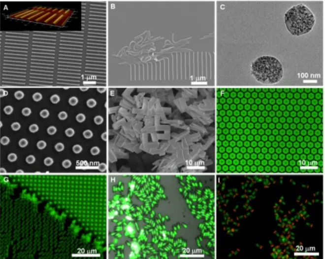
3.1 Literature examples of self-‐assembly of shape and size
specific particles………...87
3.2 Schematic of the PRINT method……….92
3.3 Dielectrophoretic cell schematic………94
3.4 Turbidity measurements of hexnut particles in three
3.5 Turbidity measurements of all four micron sized
particles in CTAB………..96
3.6 Scanning electron micrograph of each of the four particle
shapes……….98
3.7 Schematic describing particle orientation……….100
3.8 Fluorescence micrographs of particles dispersed and
aligned by dielectrophoresis………..102
3.9 Fluorescence micrographs and cartoon schematics of
crystalline particle configurations……….104
3.10 Low magnification fluorescence micrographs of aligned
particles in solution……….106
3.11 Fluorescence micrographs of hexnut and rod-‐shaped
particles on the gold electrode……….108
3.12 Atomic Force micrographs of particles on a harvesting
layer………..114
3.13 Scanning and Transmission electron micrographs of rice
and worm-‐shape particles containing magnetite……….115
3.14 Fluorescence micrograph of boomerang-‐shaped particles
in the mold with increasing amounts of magnetite……….116
3.15 Schematic detailing the alignment of chains of magnetite
in PRINT particles……….117
3.16 Fluorescence micrograph of particles with differing
orientations of magnetite……….119
3.17 Flourescence micrograph of magneto-‐polymer
composite particles aligned in a magnetic field……….121
3.18 SQUID magnetization curves of particles with magnetite
in different orientations within the particle………122
3.19 Schematic detailing the end-‐labeling and movement of
H2O2 rocket particles………..124
3.21 Multiframe fluorescence overlay of one H2O2 rocket in
H2O2 as magnetic direction is changed………127
3.22 Schematic detailing the microscope setup for H2O2
List of Abbreviations and Symbols
AC – Alternating Current
AEM – Aminoethyl methacrylate
AFM – Atomic Force Microscopy
AIBN – 2,2-bis-azobutronitrile
APMA – Aminopropyl methacrylamide
Ar – Argon
Au – Gold
AUC – Area Under the Curve
BRIC – Biomedical Research and Imaging Center
C4F8 – Octafluoroethylene
Ci – Curie
CNF - Cornell Nanoscale Science and Technology Facility
CT - Computed Tomography
CTAB – Hexadecyltrimethylammonium bromide
DEAP – Diethoxyacetophenone
DEP – Dielectrophoresis
d.i. – Deionized
DLS – Dynamic Light Scattering
DMF – Dimethylformamide
DMSO – Dimethylsiloxane
DOTA - 1,4,7,10-tetraazacyclododecane-1,4,7,10-tetraacetic acid
EDS – Energy Dispersive Spectroscopy
EDTA – Ethylendiamine tetraacetic acid
ESEM – Environmental Scannin Eelctron Microscope
Fe3O4 – Magnetite
FFF – Flow Field Fractionation
Gd – Gadolinium
H – Applied Magnetic Field
H2O2 – Hydrogen peroxide
HCl – Hydrochloric acid
HCPK – 1-hydroxycyclohexylphenyl ketone
HMDS – Hexamethyl disylazane
Hz – Hertz
i.d. - injected dose
IACUC – Institutional Animal Care and Use Committee
iTLC – Instant Thin Layer Chroatography
mN/m – MilliNewton per meter
MRI – Magnetic Resonance Imaging
N2 – Nitrogen
NH4OH – Ammonium hydroxide
NHS – N-hydroxy succinimide
NIRf – Near Infrared Fluorescence
nm – Nanometer
Pd – Palladium
PDMS – Poly(dimethyl siloxane)
PEG – Poly(ethylene glycol)
PET – Poly(ethylene terphthalate)
PET - Positron Emission Tomography
PFPE – Perfluoropolyether
PPE - Personal protective equipment
PRINT – Particle Replication In Non-wetting Templates
PS – Poly(styrene)
PTFE – Poly(tetrafluoroethylene)
PVA – Poly(vinyl alcohol)
PVDF – Poly(vinylidene fluoride)
PVP –Poly(vinyl pyrrolidone)
RES – Reticulo Endothelial System
ROI - Region of interest
SCK – Shell Crosslinked Knedel-like particles
SEM – Scanning Electron Microscopy
SPECT - single photon emission computed tomography
siRNA – small interfering RNA
SF6 – Sulfur hexafluoride
SFI-L – Step and Flash Imprint Lithography
SFL – Stop Flow Lithography
T – Tesla
TEM – Transmission Electron Microscopy
TFF – Tangential Flow Filtration
TGA – Thermogravimetric Analysis
UNC-CH – University of North Carolina at Chapel Hill
UV – Ultraviolet
V – Volt
VP - 1-vinyl-2-pyrrolidinone
λ – Denotes wavelength
µ – “micro”
µ – Micrometer
°C – Degrees Celsius
Section 1: Particle Fabrication Methods Using the Particle Replication In Non-wetting Template (PRINT) Technique
1.1 Overview of Particle Fabrication
Colloidal particles, those particles with an average diameter of 10 micrometers or
less, have been studied in detail for varied applications in catalysis, electronics,
photovoltaics, coatings, cosmetics, smart fluids, therapeutics, and diagnostics among others.
While the vast majority of colloidal particles are spherical in nature, nonspherical, or
anisotropic particles, have potential to lead to advancements in all of these applications and
more. Anisotropic colloidal particles, for example are capable of assembling into structures
which are distinct from the hexagonal close packed arrangements favored by spherical
particles and are of interest in the fields of memory storage, optical electronics, photonics and
sensors (see Section 2).1, 2
Anisotropic colloidal particles are exciting, however, not only because of the changes
in optical, electrical, and other material properties, but also because of a wealth of
advantageous biomedical properties. Precisely designed biodistribution profiles, for
example, are highly sought after and it is believed that shape specific colloids may hold the
key. In addition, enhanced tissue targeting and the ability to tote biologically relevant cargo
such as therapeutics or imaging agents make the study of these particles very intriguing.
Considerable effort has been devoted to the development of fabrication methods that
and surface chemistry. A number of different approaches towards particle fabrication are
briefly reviewed in this section with an emphasis on the control over shape and size that each
different technique is capable of. One technique in particular, the Particle Replication In
Non-wetting Templates (PRINT®) method is highlighted as an ideal method for the
fabrication of monodisperse colloids with precise control over the size, shape, material
composition, and surface chemistry of the resulting particles. The varying aspects of PRINT
are detailed below; from master and mold fabrication steps that lay the foundation of the
process all the way to finishing touches of particle fabrication including purification and
stability measurements. This section is a summary of lessons learned in particle fabrication
and is designed to provide a detailed snap shot of the ever-evolving PRINT process.
1.1.1 Bottom-Up Approaches to Particle Fabrication
Two broad approaches are amenable for the fabrication of anisotropic particles:
bottom-up and top-down techniques. Bottom-up approaches begin at the atomic or
molecular scale and build up to the desired particle size, while top-down methods process a
material on the desired size scale. The most commonly employed methods for the
production of mass quantities of particles on the colloidal length scale are bottom-up
synthetic approaches such as emulsion polymerization. In a typical process, a monomer is
emulsified via rapid stirring in a mobile phase that contains an initiator and a surfactant.
Upon heating to activate the initiator, spherical particles are nucleated in the surfactant
micelles and grow to the desired size. Particles obtained by emulsion methods are typically
spherical and can vary in size from tens of nanometers to several microns in diameter. The
particle size and the molecular weight of the polymers formed in emulsions are controlled
adsorbed onto the surface of these particles can be difficult to remove if undesired. While
this method is extremely scalable, the particles fabricated in this way are typically spherical
in shape, can have large polydispersities and are limited in chemical composition.
Particles with non-spherical shape are of increasing interest for biomedical
applications such as drug delivery, where the rod-like or corkscrew morphologies possessed
by many viruses and bacteria are suspected to have derived an evolutionary advantage from
their specific shapes.3 Crystals of many metals and metal-oxides can be grown into both
spherical and anisotropic shapes such as cubes, rods, discs and faceted polyhedra using
nucleation and arrested growth strategies.1, 4, 5 More complex branched structures can be
formed by sequential growth of dots and rods of different materials.6 Such nucleation and
growth methods are limited to inorganics and the shape selectivity is highly dependent on the
material and its crystal structure. Further, these inorganic materials often lack the capability
to encapsulate a cargo or undergo surface modification.
Bottom-up approaches for the fabrication of organic particles have received a great
deal of attention for use in biomedical applications such as imaging, gene or drug delivery.
These methods chiefly rely on self-assembly of amphiphilic molecules to create micelles,
vesicles, liposomes, and polymersomes. The hydrophobic interior is able to encapsulate a
hydrophobic cargo. While spherical particles have been the standard, increasing attention
has been directed towards higher aspect ratio particles (particles that are taller than they are
wide) that are achievable with control of the relative length of hydrophobic and hydrophilic
domains.3, 7-9
An example of high aspect ratio particles was recently demonstrated by Discher, et.
persistence and ability to encapsulate and deliver chemotherepeutics. The filomicelles were
prepared from block copolymers with lipid-like amphiphilicity, but a more symmetric ratio
of hydrophilic to hydrophobic blocks than is found in lipids. These filamentous particles
persisted in the circulation about ten times longer than spheres with similar surface
chemistry, and were successful in encapsulating and delivering a hydrophobic
chemotherapeutic to tumored mice.9 One criticism of these self-assembled systems is the
dynamic nature of the particles so assembled. With membrane components held together
with attractive forces rather than with covalent bonds, the structures generated can add or
lose components, making their size and shape more fluid than may be desired. The dynamic
nature of these self-assembled systems has been addressed by Wooley et al. with shell-cross
linked knedel-like particles (SCKs).10-13 These block copolymer micelles are modified with
reactive groups on the surface which can be chemically cross-linked after self-assembly,
giving superior stability to their structure.
1.1.2 Top-Down Approaches to Particle Fabrication
Top-down approaches to particle fabrication rely on tools, rather than surface energy
and thermodynamics like so many bottom-up approaches, to tailor the size and shape of
particles. “Crude” top-down methods are popular in the fabrication of bulk materials.
Examples of this include milling and grinding in which particle size distributions are highly
disperse and shape is very irregular. Sorting for particle size is possible using a variety of
techniques including sieves and fractionation. A number of new top-down techniques have
been developed that offer substantial benefits in the control over size and shape. Examples
of these techniques include template based, microfluidic, mechanical stretching, and
1.1.2.1 Hard-Template Approaches to Top-Down Particle Fabrication
Hard-template methods have been used to prepare nanowires, nanotubes and
nanorods.14-17 In this technology, porous templates are filled with one or more materials to
fabricate monodisperse nanoparticles. Traditionally, the templates are filled via
electrochemical means. This is accomplished by first depositing a sacrificial metal layer,
such as gold or silver, on one side of the template for electrical contact. Then, the material or
materials of interest are electrochemically deposited into the pores of the template. For
example, metals can be synthesized using the appropriate electroplating solution, and
conducting polymers can be synthesized via oxidative polymerizations. After deposition, the
template is dissolved yielding an ensemble of nanoparticles connected at the base to the
substrate metal. The connecting sacrificial metal layer is then dissolved to generate a
monodisperse suspension of high aspect ratio nanoparticles. Both tubes and solid wires or
rods can be prepared depending on the surface treatment of the template.18 One major
advantage of the template method is that segmented or multicomponent nanoparticles can be
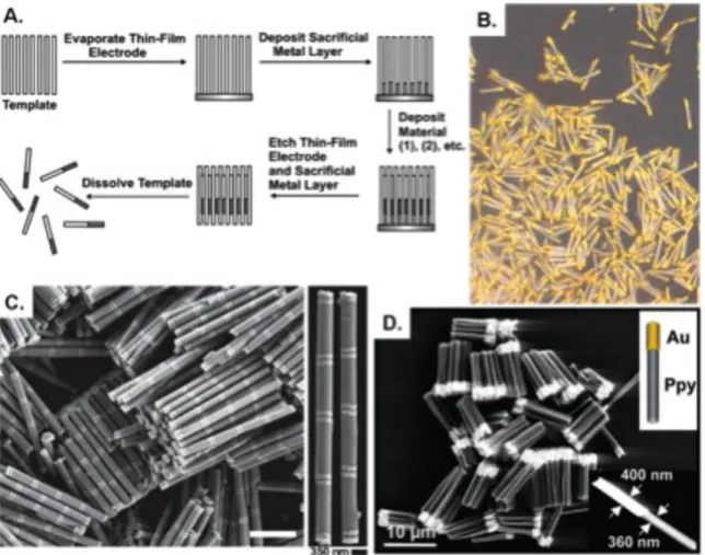
fabricated in a rational fashion (Figure 1.1).19, 20 This has led to an impressive breadth of
research into the area of post-fabrication modifications of segmented nanoparticles.21
Multicomponent nanorods can be selectively functionalized for different multiplexing,
Figure 1.1. (A) General scheme for nanorod synthesis via the deposition of materials into a nanoporous template,19 (B) Bright-field optical micrographs of Au/Pt/Au rods,22 (C) SEM images of Au-Ni multisegmented nanorods,23 and (D) SEM image of Au-polypyrrole rods.20
1.1.2.2 Microfluidics Approaches to Top-Down Particle Fabrication
One emerging strategy for the fabrication of particles with control over particle size
and shape is fabrication with microfluidic devices. In early microfluidic particle fabrication
studies, the shapes produced in these channels were limited to spheres, cylinders and
spherically derived shapes such as discs and ellipsoids. More complex and chemically
anisotropic shapes such as hemispheres25, core-shell25 and janus particles26 were produced by
confining the droplets with the geometry of the device and with coflowing laminar streams,
has developed photolithographically coupled approaches, which have produced more
complex shapes by use of a photolithographic mask.27, 28 Particles were crosslinked by the
UV light exposure almost instantaneously, and did not plug up the channel due to the oxygen
mediated inhibition of polymerization at PDMS surfaces, which left a thin layer of
unpolymerized monomer at the channel walls.29 Exposures across several fluid streams
resulted in the formation of janus type particles with two or more chemically distinct regions
on each particle.27, 30 Higher resolution has been achieved with the use of stop-flow
lithography (SFL), a process during which the flow of monomer was stopped briefly during
each exposure. Complex shapes have been formed with high resolution in the micron scale,
including a range of concave and convex sided pyramids, rectangles, and spheres, and
rectangular toroids - all with multiple, chemically distinct phases possible.28, 31
Microfluidic methods have demonstrated their versatility in terms of particle shape
and chemical anisotropy of the particles produced (see Figure 1.2). The emergence of SFL
techniques have increased the resolution of this technique though there are material
limitations; particles made in this way have been limited to polymerizable fluids and
selection of the mobile phase has been limited due to the swelling of the device material,
PDMS, in many solvents. Another limitation has been the size of particles which can be
produced with these methods. Particles on the order of 3-100 µm were readily fabricated, but
sub-micron particle sizes remain a challenge for microfluidic technology.
Figure 1.2. (A) Illustrations of the three main microfluidic geometries used for droplet formation,32 (B) A schematic used for continuous-flow lithography and (C) microparticles of varying shapes fabricated with this method,27 (D) Right: A schematic for the channel and flow configuration used for the formation of the bicolored janus particles shown on the left.33
1.1.2.3 Mechanical Stretching as a Top-Down Approach to Particle Fabrication
One relatively new method for the fabrication of shape and size specific colloids
relies on the mechanical stretching of spherical particles. Particle stretching was initially
used to deform polystyrene (PS) particles that were embedded in a polyvinyl alcohol (PVA)
film. Upon heating to a temperature at which the particles could deform, the film was
stretched, then rapidly quenched, yielding ellipsoidal particles upon dissolution of the PVA
fim.34 Recently, Champion et. al. reported the formation of complex shapes via a similar
method (Figure 1.3). In this method, as before, (PS) particles were embedded in a PVA film.
The PS particles were liquidized by addition of heat or solvent, allowing the PS to flow,
filling void spaces in the surrounding film, or to stretch with the film due to hydrogen
bonding based attraction to the surrounding film. Manipulation of the PS particles required
stretching protocol allowed for selective formation of over twenty distinct particle shapes
upon solidification of the particles by cooling or removal of solvent and subsequent release
from the PVA film.35
One distinct advantage of the particle stretching technique has been the ability to
compare differently shaped particles with identical volumes by preparing different particle
shapes from the same stock of spherical particles. Material compatibility is a concern for this
method, as the bulk of the literature deals with PS and poly(lactic-co-glycolic acid) (PLGA)
based particles – though one can imagine that many materials could be manipulated in this
way by adjusting the conditions used to fluidize the particles and the material in which the
particles are embedded. This method is versatile with respect to particle size, as spherical PS
particles with diameters from 60 nm to 100 µm have been subjected to these stretching
protocols. Polydispersity of the particles prepared by stretching methods was reflected by
the polydispersity in the spherical particles before stretching. Careful selection of a spherical
particle source could lead to the formation of more monodisperse populations of stretched
Figure 1.3. (A)The two general schemes used in stretching spherical particles to different shapes. In Scheme A, particles are liquefied prior to stretching the film, while Scheme B has the film stretched prior to particle liquidification. (B) Polystyrene particles prepared via the method shown in scheme A. (C) Polystyrene particles prepared Scheme B.35
1.1.2.4 Photolithographic Approaches to Top-Down Particle Fabrication
Photolithography, the workhorse of the semiconductor industry for high volume
manufacturing36, 37, has also been directly applied to the fabrication of discrete monodisperse
colloidal particles.38-41 A simple illustration of this process is shown in Figure 1.4A. Both
Mason et al.39 and Stroock et al.42 have reported using this type of approach to generate
highly monodisperse, shape-specific colloidal particles. Stroock et al.43 demonstrated the
ability to tailor the surface roughness of the particles by modifying the development
conditions (Figure 1.4 B). Mason et al.39 illustrated the shape versatility of this process by
English alphabet. The fabrication of the lithographically-derived particles, or LithoParticles
as coined by Mason, was also found to be amenable to the incorporation of both organic dyes
and nanoparticles such as iron oxide. It was even feasible to fabricate hybrid bilayer Janus
particles, through the successive exposure of two different masks.
Clear advantages of this type of processing include excellent shape fidelity down to
the submicrometer level and the ability to fabricate particles in a high throughput fashion. A
major stumbling block for using this process is the enormous capital required to continuously
run such an expensive lithographic exposure system. Another issue with this type of
processing is the limitations in the chemistries that can be used in the particle fabrication.
These issues have led to the development of alternative routes to LithoParticle production
that take advantage of templating, where only the initial reusable template requires
photolithography.44, 45
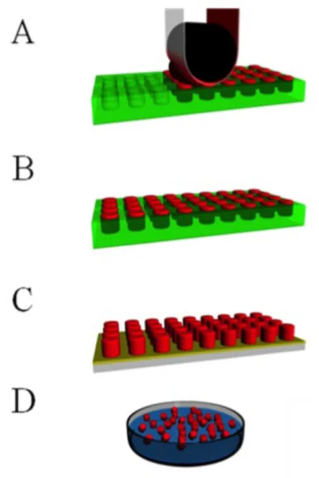
Figure 1.4. (A) Simple scheme showing the photolithographic fabrication of colloidal particles,42 (B) Cylindrical photoresist particles engineered with rough side walls (particle radius = 520 nm, height = 875 nm),43 (C) Photoresist particles of varying shapes (scale bars represent 3 µm): square donuts, square crosses, triangular prisms and pentagonal prisms
Imprint lithography based methods have emerged in recent years as promising
techniques for scalable fabrication of shape specific colloidal particles. Soft lithography
based techniques, which were pioneered by Whitesides et al. in the late 1990’s, begin with
the use of a rigid template which is used to fabricate an elastomeric mold, which can then be
used to replicate the shape of the original template in a molding or stamping process.46
Imprint methods were first envisioned as a high-resolution, low-cost alternative to traditional
photolithograpic techniques for micro- and nanoscale pattern replication rather than
fabrication of distinct particles. Particle fabrication has been a challenge due in large part to
the persistent formation of a residual layer of molded material, called a flash layer, which
connects the potential particles.47 Much attention has been directed towards the removal or
avoidance of this flash layer with the goal of particle fabrication. Step and flash imprint
lithography (S-FIL) uses a rigid, UV transparent template as a mold material, creating an
embossed film of particles from a UV curable material. The interconnecting flash layer is
removed by an etching step, with dissolution of a sacrificial layer yielding distinct
particles.48, 49 Removal of the flash layer via an oxygen plasma etch can be energetically
expensive and time consuming.
Soft lithography applications that utilize crosslinked poly(dimethyl siloxane) (PDMS)
elastomer, typically result in particles connected by a flash layer. Recently, microparticles
were fabricated with PDMS molds without formation of a flash layer by careful applications
of photocurable acryalte resins, as well as aqueous and organic solutions of polymers, to the
molds.50 Surface treatments were shown to increase or decrease the hydrophilicity of the
mold, facilitating mold-filling, mold de-wetting, and particle release.51, 52 PRINT technology
technique, allows for facile fabrication of distinct particles without formation of a flash layer
while maintaining many of the advantages of the soft lithography technique and avoiding
some of the difficulties associated with PDMS.53
1.2 Particle Replication In Non-wetting Templates (PRINT)
1.2.1 PRINT Overview
In 2004, Rolland et al. reported the synthesis of a new perfluoropolyether (PFPE)
based elastomer54, a material that proved to be more effective than PDMS as a template for
soft lithography based particle fabrication. Photocurable PFPE (FluorocurTM, Liquidia
Technoligies Inc., NC) was synthesized by endcapping a fluorinated PFPE diol (Solvay) with
isocyanatoethyl methacrylate to form PFPE dimethacrylate. The end-functionalized
fluorinated oil had a positive spreading coefficient allowing it to completely wet and
envelope the delicate details of a master template. Curing of the oil was accomplished under
UV light (365 nm, ~10-15,000 mJ/cm2) after the addition of a photoinitiator. The resulting
PFPE elastomers have three distinct advantages over silicone templates for use in soft
lithography. First the low surface energy of the elastomer (8-10 dyn/cm)55 facilitates the
removal of an excess flash layer. Other lithographic methods typically require an etch step to
remove this layer, complicating the scale up of these methods.46, 56 Second, PFPE was
observed to be compatible with a number of organic solvents that were incompatible with
silicone molds.54 It was found that, while both Sylgard 184 (a silicone material) and PFPE
molds exhibited negligible swelling in the presence of water and methanol, Sylgard 184
molds were permeable to toluene and dichloromethane. An examination of several other
common solvents and polymerizable organics showed a similar trend, with PDMS coupons
generally showing a higher retention of these organic fluids (table 1.1). With the elimination
of swelling, master-to-replica fidelity was improved and the reproduction of much smaller
feature sizes was possible. In 2006, Maynor et al. showed that a variety of nanoscale
nm polymeric toroidal micelles, and single walled carbon nanotubes with heights as low as 2
nm.55 Third, the highly fluorinated nature of the mold (similar to that of TeflonTM) facilitated
the removal of particles from the mold. In contrast, other soft lithography methods required
surface modification of the molds to facilitate particle removal.51, 52 A number of published
manuscripts are available describing a wide variety of particles fabricated using the PRINT
technique (Figure 1.6)8, 53, 57-64
Table 1.1. A comparison of swelling behavior, reported as the percent increase in weight of coupons of crosslinked elastomeric materials after soaking overnight. Traditional soft lithography mold material, poly (dimethylsiloxane) (PDMS), and PRINT mold material, perfluoropolyether (PFPE) were compared with regards to several solvents and polymerizable monomers.65
PDMS
(weight % uptake) PFPE (weight % uptake)
Water 0.37 ± 0.04 0.39 ± 0.16
Hexane 109.82 ± 1.41 1.72 ± 0.25
THF 145.46 ± 1.68 6.95 ± 0.08
DMSO 2.36 ± 0.50 1.98 ± 0.17
Isopropanol 17.65 ± 2.44 2.38 ± 0.06
Acetone 20.15 ± 1.05 4.81 ± 0.06
Poly (ethylene glycol) methyl ether 1.04 ± 0.45 0.36 ± 0.07
2-hydroxyethyl acrylate 1.45 ± 0.23 1.03 ± 0.22
N-Vinyl-2-pyrrolidone 5.55 ± 0.31 2.34 ± 0.27
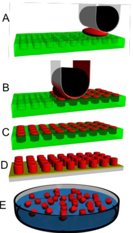
Figure 1.6. Illustrative examples of size, shape, composition, cargo and surface chemistry control with the PRINT process (A-B) 80 nm x 2000 nm worm-like cross-linked poly(ethylene glycol) (PEG) nanoparticles on a harvesting layer, inset showing AFM image of harvested layer, (C) 10 wt. % iron oxide-loaded 200 nm cylindrical cross-linked PEG particles, (D) siRNA-loaded 200 nm albumin nanoparticles harvested onto a medical adhesive, (E) boomerang-shaped linked PEG microparticles, (F) hexnut-shaped cross-linked PEG microparticles on a cyanoacrylate harvesting layer, (G-I) 2x2x6 mm cross-cross-linked PEG rectangular prisms showing increasing chemical anisotropy: (G) one-phase, (H) biphasic, and (I) triphasic. D62 and H, I.66
1.2.2 Master Fabrication
Typically, patterned silicon wafers were used as masters from which a pattern is
transferred to a PFPE mold. Fabrication of silicon masters was performed using standard
photolithographic instrumentation and techniques. In its most basic form, photolithography
passed through a patterned reticle. The light induces a change in solubility in the photoresist.
In a positive photoresist, whatever is exposed becomes soluble. This change in solubility is
typically due to the cleavage of a photoacid generator group pendant to the backbone of the
polymer. In negative photoresists crosslinking occurs upon exposure to light that eliminates
the ability to dissolve the exposed regions. After exposure and removal of the soluble
portion of the photoresist, one of any number of etching processes can be used to etch the
silicon. Finally, cleaning steps are used to remove residual photoresist from the wafer.
Achievable feature sizes for each technique are largely dictated by the wavelength of light
that is used to expose the photoresist.
Patterned masters with micron scale features were fabricated at the Cornell Nanoscale
Science and Technology Facility (CNF). Briefly, 4 x 4” chrome on glass reticles (50 mm
field size) were either fabricated using a Heidelberg DWL66 Mask Writer or they were
purchased from Holographix, LLC. Feature sizes in the reticle were 5 times the size of the
desired features of the master. Wafers were cleaned with 1:1 NH4OH:H2O2 then with 1:1
HCl: H2O2 and were rinsed with d.i. water and dried (a process known as metal-oxide
semiconductor (MOS) cleaning). Wafers were then primed for photoresist with hexamethyl
disylazane (HMDS) using a YES LP-III vacuum oven. Next, the wafers were placed in a
Brewer Science CEE Model 600 and were coated with SPR 220-3.0 photoresist which was
spun cast at 5000 rpm for 60 seconds. The wafers were baked at 115 °C for 60 seconds to
remove residual solvent then cooled to room temperature. Photoresist along the edge of the
wafer was removed to facilitate later etching steps. After edgebead removal, micron scale
feature sizes (0.5, 1, 2, 3, 5, 7 and 10 µm) were exposed into photoresist using a GCA
exposed photoresist was then developed with 300 MIF developer for 60 seconds using a
Hematech-Steag Wafer Processor. An O2 plasma clean was then performed to remove
excess photoresist. To etch the silicon, a Bosch Etch procedure was employed using a
Unaxis 770 couple plasma/reactive ion etcher. The etching process used C4F8, SF6, and Ar
gases for an etch rate of 1 µm/minute. Finally, any residual photoresist was removed from
the wafers in a two part process involving first, a two tank hot resist strip bath/rinse/dry cycle
and second, a 15 second oxygen plasma removal cycle a Branso P2000 barrel etcher. Silicon
masters were characterized by SEM.
Masters with smaller feature sizes (< 500 nm) were provided by Liquidia and were
typically made using 193 nm photolithography technology. Other lithographic techniques
with even higher resolution are available. E-beam photolithography for example, is capable
of creating 10-20 nm feature sizes. Anoter technique using self assembled block copolymer
masters have been shown to be effective in highly regular feature sizes smaller than 20 nm.67
1.2.3 Mold Fabrication
Initially, mold fabrication was performed by drop casting 20-30 mL of Fluorocur
resin onto a 6-8 inch diameter patterned silicon master template that was then cured
photochemically in a UV oven.53 Molds were released from the template by slowly peeling
them back from silicon wafer using PTFE tweezers so as not to scratch the fragile surface
features. Because of the delicate nature and the high cost associated with using large
quantities of Fluorocur Resin for the thick molds, the scale of particle production was
limited. With this in mind, a proprietary roll-to-roll system capable of producing thousands
of linear feet per day of PFPE molds on a flexible poly (ethyleneterephthalate) (PET)
more mechanically robust molds and reduces the Fluorocur resin requirements by several
orders of magnitude making the process more time effective, less costly, and highly scalable.
Thin molds have also been successfully fabricated in the lab. Typically, a 500 µL
aliquot of Fluorocur is gently spread over a silicon master using a sheet of PET specially
treated for adhesion with PFPE. Air bubbles are removed from between the master and the
PET by peeling the PET all the way off of the PFPE-wetted master surface and gently rolling
the PET back over the master using a small hand roller. The master/PFPE/PET sandwich is
then placed in a UV oven which is then purged of O2 using N2. The mold is cured for 3
minutes and allowed to cool to room temperature. The mold is then gently peeled off the
master revealing a clean mold bound to a PET backing sheet.
1.2.4 Mold Filling
Filling of any patterned mold is a process that relies heavily on surface energies of the
materials in play. In order to effectively fill the cavities, a pre-particle solution should have
the ability to partially wet the surface of the mold. Solutions capable of wetting the surface
of a mold are drawn into the mold cavities by capillary forces. At this point excess
pre-particles solution covers the entire surface of the mold in what is referred to as a flash layer.
Excess pre-particle solution was removed by first laminating the filled mold with a high
surface energy material (i.e. PET, surface energy = 42.1 mN/m)68 and second, peeling back
the laminate material. Capillary forces trap the liquid in the mold while excess solution
adheres preferentially to the high surface energy material and is wicked away, leaving
isolated reservoirs of pre-particle solution, thus eliminating the need for a scum removal step.
Film thickness of the pre-particle solution, like surface energy, also plays an
removal of excess solution difficult and often lead to the formation of scum. Films that are
too thin lead to patchy filling or shortened particles. As such, uniform films were drawn on a
PET sheet using a metal Mayer rod with grooved surface features and a mechanical film
coating instrument (R.D. Speicialties Inc). Film thickness was dictated by both the grooved
feature size of the Mayer rod and the concentration of the pre-particle solution. Best results
were observed when the film thickness was on the order of the feature height of the mold.
For example, a 200 nm tall particle would fill best with a 200 nm film. In addition, it was
determined that performing the filling and splitting steps in one continuous movement
provided the best results.
Unlike patterning on a solid substrate, or with a rigid patterned template which can be
time consuming, patterning of the pre-particle solution can be done in a continuous fashion
when the template and pre-particle solution are both on flexible backing. Other particle
fabrication methods like S-FIL involve a step by step procedure in which a master template is
brought into contact with a solid substrate in the presence of a pre-particle solution, a step
that can damage the master template if performed without care. In the PRINT process, after
a uniform film was cast on PET as described above, the PET was laminated to an empty
mold using an in-house single-nip lamination system. Lamination conditions (pressure,
speed, temperature, and humidity) were optimized for each new class of particle.
Monomer-based pre-particle films that flowed freely into the cavities of the mold and had low vapor
pressure were laminated at room temperature.61 Volatile monomers and other small
molecule systems required that the lamination temperature be reduced and that the lamination
sometimes required heat to raise the temperature of the film above the glass transition
temperature of the polymer allowing the polymer to flow into the mold.
1.2.5 Particle Curing and / or Solidification
While the majority of “Top Down” particle fabrication processes rely on
photochemical curing, particle solidification using the PRINT technique can be quickly
accomplished by a variety of different methods. Monomer systems incorporating a small
amount (~ 1 % or less) photochemical initiator such as 1-hydroxycylohexyl phenyl ketone or
2,2-diethoxyacetophenone (HCPK and DEAP, Aldrich) were cured in a UV chamber.63
Some monomeric pre-particle systems that were sensitive to light were instead cured
thermally using a temperature sensitive initiator such as 2,2-bis-azobutronitrile (AIBN,
Aldrich). Polymeric systems cast from a solvent were dried and solidified under vacuum
while neat polymeric systems were dropped below their glass transition temperatures causing
them to become glassy and solid. Small molecule and protein based “biological” systems
that were cast from a solution were typically lyophilized.62
Particle solidification, regardless of the chemical process of solidification, was
typically performed either closed-faced, with a PET sheet laminated to the surface of the
filled mold or open-faced69 with the filled mold exposed to a N2 purge. Solidified particles
trapped in the mold or bound to a harvesting layer of PET could be harvested immediately or
wound up and stored until harvesting at a later date.
1.2.6 Particle Harvesting
In early particle fabrication experiments using the PRINT method, removing particles
from the mold was initially performed by physical agitation of the particles with the sharp
First, this method was found to damage the surface of the molds creating large chunks of
PFPE mold that would have to be filtered out later. Second, scraping dry particles could
cause them to aerosolize. And third, the harvesting process was not scalable. With the
introduction of thinner molds from, scraping caused even more damage to the molds than
with the thick PFPE molds because there was less elastomeric material to dampen the force
of the scraping glass edge.
As a result, new harvesting techniques were developed that were more gentle, safe,
and scalable. If solidified with an open face as noted above, the particles in the mold could
be laminated to an adhesive layer such as poly(vinyl pyrrolidone) (PVP) or cyanoacrylate on
a flexible or rigid backing such as PET or glass slides. Once the adhesive solidified, the
mold was peeled away from the substrate revealing an array of free-standing particles. The
adhesive was then dissolved and the particles collected in solution. This method was found
to be especially useful for larger micron scale particles that required the strength of
cyanoacrylate to be removed from the mold.
While this method appears straightforward in its implementation, it can be difficult to
successfully harvest particles in this manner. The reasoning behind this, is that particles are
strongly trapped within the cavities of the mold by capillary forces and Van der Waals
interactions with the PFPE. As a result a great deal of force is required to remove the
particles from the mold. This means that any adhesive used to perform this task needs to
have strong interactions with the surface of the particle. Therefore the sacrificial adhesive
layer needs to be chosen with each particle’s surface chemistry in mind. Hydrophilic
If the particles were solidified with a closed face (laminated to PET), the particles
adhered to the raw PET once the mold was peeled back. This works well for particles that
are hydrophobic in nature (ie. triacrylate or poly(styrene)-co-poly(butadiene)). For particles
that are more hydrophilic (ie. particles with long PEG chains or charged monomers), the
surface energy of PET was readily increased through the process of corona surface treatment.
Pre-treated PET sheets (Melinex 453) were also used for higher surface energy removal of
hydrophilic particles. Caution here is necessary as curing particles in the presence of a
surface that is too similar in nature can lead to irreversible binding of the particles to the
surface. Once removed from the mold, free-standing particles that are physisorbed to a sheet
of PET can be harvested by lamination to another adhesive layer or by physical agitation
with a soft rubber cell scrapper in the presence of a solvent.
1.2.7 Particle Purification
Regardless of the fabrication method, after harvesting, particles made from
“Top-down” techniques generally require some form of purification to remove debris or residual
compounds from the fabrication process, and also to prepare particles for their intended use.
As mentioned above, when using AAO as a template, particle fragmentation often
occurred.70 Even particles that only required minimal manipulation by physical stretching
on a sheet of PVA required multiple rinsing steps to remove excess PVA from solution.35
Fortunately, a wide variety of purification methods are currently available and it is usually
possible to find at least one method that fits well with a particle fabrication technique.
Dialysis (>100,000 MWCO, Float-a-lyzer, Spectrum Labs, Inc) was originally used
for PRINT particle fabrication to remove impurities such as sol fraction and to exchange
because particles were often physisorbed to the membrane surface. In a typical purification,
spent solvent had to be switched for clean solvent at least three times over the course of 1-2
days.
Centrifugation is perhaps the simplest method of particle purification and it is used
widely as a quick method to rinse particles and separate various sized populations of particles
gravimetrically.58 In centrifugation, particles are spun out of solution under high centrifugal
forces. As particle size decreases, the centrifugal speed and the time required to effectively
pellet out particles effectively increases. Particle yield can be reduced when centrifugation
is halted prematurely. As such, purification of small stable particles, less than a few hundred
nanometers in diameter, can be quite time consuming requiring hours or days to fully pellet a
sample. Other problems including irreversible aggregation may be encountered when
particles are centrifuged for long periods (>1hr) at high speed (14,000 rpm / 20,000 G).
Additionally, resuspending pelleted particles by vigorous mixing and/or sonication can
damage particles composed of less robust matrix materials or with high aspect ratios as well
as fragile cargos, such as proteins and other biologically active cargo, and should be
performed with care.
Centrifugal filtration using 0.1 µm cutoff poly(vinylidene fluoride) (PVDF)
membranes (Microcon-MC, Millipore) proved to be an efficient alternative to standard
centrifugation. Lower speeds are required than normal filtration and therefore aggregation is
typically reversible. Unfortunately, once spun down, particles are partially adhered to the
PVDF membrane. The strength of particle adhesion to the membrane depends strongly on
both the chemistry of the particles as well as that of the membrane. Removal of particles
from its housing and sonicated in solution. While a variety of polymeric membranes and
pore sizes are available making this technique adaptable for a variety of particle fabrication
methods, particle loss is often dramatic (as much as 50% loss of mass), and the batch process
with repeated rinsing can be slow and therefore it is not ideal for high throughput particle
fabrication.
Filtration using indirect or tangential flow filtration (TFF) systems appeared to be the
most promising approach for particle purification. In TFF filtration systems such as KrosFlo
(Spectrum Labs, Inc) particle solutions traveled tangential to the membrane. Both
diafiltration as well as concentration are possible without changing particles from one set up
to another. Particle loss by adsorption to the membrane and to surfaces was reduced as
particles were not forced to interact directly with the membrane or multiple vials and/or pipet
tips. Stirred Cell filtration (Millipore), another indirect filtration method, was also examined.
While this method of purification appears promising, inadequate stirring can lead to filters
clogged with particles creating prolonged filtration times. Additionally, if the cell is allowed
to run dry, dramatic loss of particle yield is observed due to irreversible adhesion of the
particles to the filter membrane.
Other methods of particle purification are also under development. Magnetic
purification for example is currently being used for particles containing magnetic cargo.
While it was strictly limited to magnetic particles, this method, using magnetic columns
(Minisep, Miltenyi Biotec) appeared promising for purification and other functionalized
particle applications. In addition to magnetic filtration, Flow Field Fractionation (FFF) is of
interest for future purification and separation of particles as particle aggregation is not as
1.2.8 Particle Surface Modification
One unique feature of template based particle fabrication is that solidified particles,
either in the mold or on a harvesting layer of PET, are easily subjected to a number of
regiospecific chemical modifications.66 Chemical modification of particles while in the mold
made it possible to manipulate one face of the particle. Once removed from the mold,
modification of particles on a harvesting layer allowed the manipulation of the remaining
sides of the particle. This is an exciting development for a number of fields of research
including nano- and microrobotics 71-73 and targeted drug delivery.66 Ongoing research in our
lab is focused towards directed cellular uptake of regio-modified particles as well as the
beginnings of shape-specific building blocks for directed assembly in smart fluids and
microrobotics applications.
1.2.10 Particle Characterization
Particles were analyzed using a number of different techniques. Techniques for
imaging particles included scanning electron microscopy (SEM), transmission electron
microscopy (TEM), atomic force microscopy (AFM), optical and fluorescence microscopy.
Surface chemistry and stability was determined using dynamic light scattering (DLS), zeta
potential analysis, and turbidity as well as a number of other indirect assays that are
described in detail in later sections. Particle concentration was typically determined
gravimetrically using a thermogravimetric analysis (TGA) instrument. While individually,
each method provided one or two attributes of a particular particle sample, typically a
combination of the above characterization techniques was required to get the full picture of
what a particle sample was. Below are typical conditions and sample preparations for each
1.2.10.1 SEM
SEM was used as a method to rapidly examine particle morphology. Particle samples
were imaged by SEM in an array (ie. harvesting layer) or cast from solution. When cast from
solution, particles were thoroughly rinsed with filtered deionized (d.i.) water then drop cast in
low (0.001 mg / mL), medium (0.1 mg / mL), and high (1-10 mg / mL) concentrations onto a
clean glass slide. After drying at room temperature the particles were coated using with 3 - 5
nm gold / palladium using a Model 108 Auto Sputter Coater (Cressington Scientific
Instruments). Particles were then imaged using a Hitachi model S-4700 SEM at 2 kV
acceleration voltage. A typical SEM of 200 x 200 nm PEG-based PRINT particles is shown
in Figure 1.7.
Figure 1.7 Scanning electron micrograph of 200 x 200 nm cylindrical particles on a harvesting layer of PET.
TEM was often used to examine the loading of magnetic iron oxide into the core of
the particle. Samples were prepared by dipping a carbon-formvar coated TEM grid into
aqueous dispersion of particles of varying concentrations (see above). The samples were
wicked dry using a piece of filter paper and allowed to dry completely at room temperature.
Samples were then imaged as is using a Jeol 100 CX II instrument with a 40 kV acceleration
voltage operating in bright field mode. A typical example of a 200 x 200 nm particle with
encapsulated iron oxide nanoparticles is demonstrated in Figure 1.8.
Figure 1.8 Transmission electron micrograph of 200 x 200 nm cylindrical particle containing 10 wt % iron oxide nanocrystals.
Samples were typically imaged in an array in order to determine the depth of filling in
the mold itself or to determine the height of particles on a harvesting layer. Samples were
prepared for AFM by adhering a small square to the sample stage using cyanoacrylate
adhesive which was allowed to dry at room temperature for 10 minutes. The sample was
then imaged using a Nanosurf Easyscan 2 AFM (Nanoscience, Inc.) in dynamic contact
mode using an ACLA tip. Examination of an 80 x 2000 nm patterned PFPE mold by AFM is
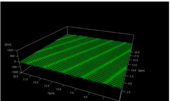
demonstrated in Figure 1.9.
Figure 1.9 Atomic force microscopy image of a patterned PFPE mold with 80 x 2000 nm “worm-like” surface features. The AFM image shows that the mold is clean and free of defects.
1.2.10.4 Particle Stability
Particle stability was determined either by dynamic light scattering or by turbidity
experiments, a spectrophotometric technique that monitors the transmittance of light through
electrolyte (1.0 mM NaCl). Typically, both Zeta and DLS experiments were performed at 25
°C and could be run in the same cuvette using the Malvern Instruments Zetasizer Nano ZS
equipped with an autotitrator. Particle polydispersity and hydrodynamic radius were
determined. Low polydispersity (PDI < 0.1) and particle sizes slightly larger than the feature
size of the mold used to make the particle indicated that the particles were stable and had not
formed large aggregates in solution. Particle isoelctric points were determined using this
instrument providing crucial information on the operational pH range of the particles.
Turbidity was useful in determining how stable concentrated samples of particles
were. Particle samples (5-20 mg/mL) were prepared in 0.2, 1.0, and 5.0% (w/v) aqueous
CTAB solutions. The particle sample in a cuvette (100 µL, QS) with a path length of 1 cm
was then vortex mixed and placed in a plate reader (Spectra Max M5, Molecular Devices). A
kinetic experiment was performed at 490 nm, and an absorbance reading was taken every 30
s for 1 h at 22 °C. All experiments were repeated three times to establish reproducibility.
The turbidity, τ, defined as the attenuation of the light beam by scattering when passing through a sample, was determined from equation 1.1, where Io is the incident intensity of
light, It is the transmitted intensity, and l is the optical path length. See Section 3 Chapter 2
on particle stability for an example of turbidity experiments.
€
λ=l−1ln(I
o/It) (eq. 1.1)
1.2.10.5 Particle Concentration
Accurate particle concentration was essential for all experiments and particle
analysis. Therefore a rapid, effective means of particle concentration determination using
TGA was developed. In a typical experiment, a 25 µL aliquot of purified particle dispersion