PDF: 09005aef822f5f67 / Source: 09005aef822f5fbb Micron Technology, Inc., reserves the right to change products or specifications without notice.
1
Technical Note
Booting from Embedded MMC
Introduction
MultiMediaCard (MMC) technology provides low-cost data storage media for many mobile applications. MMC benefits include:
• Royalty-free design
• Industry-standard interface
• High-performance, 8-bit, 52 MHz I/O interface
MMC devices handle NAND Flash chores such as wear leveling and error correction, freeing the host system from these tasks.
This technical note describes booting from an embedded MMC device—such as Micron’s e-MMC™ embedded memory—and provides supporting documentation for designers incorporating MMCs in their applications. It draws on the MMC specification published by the MultiMediaCard Association and includes details from that specifica-tion (the complete specificaspecifica-tion is available at: www.mmca.org/home).
Booting from
e
-MMC Embedded Memory
To implement Micron’s e-MMC solution as the single nonvolatile memory device in an embedded system, the system must boot up from the e-MMC device.
e-MMC embedded memory does not inherently support execute in place (XIP). Oper-ating system (OS) code and boot code can be stored in the e-MMC device, but the code must be copied (or shadowed) to RAM before it can be executed. Because of this, system designers must modify the boot process to support code shadowing from an e-MMC device. The benefits of this modification are the lower cost of e-MMC embedded memory as the storage media and the high performance of RAM as the XIP memory. This document focuses on booting from a Micron® e-MMC device in applications using a 32-bit ARM® processor. Each stage in the boot sequence process is described in detail. Terms and abbreviations used in this technical note are defined in Table 1.
Table 1: Terms and Abbreviations
Abbreviation Description Abbreviation Description
CID MMC device ID DAT MMC data signal
CMD MMC command signal MMC MultiMediaCard
CRC Cyclic redundancy code e-MMC Micron’s embedded memory device CSD Card-specific data
MMC Bus Description
MMC Bus Description
The CLK, CMD, and DAT[7:0] pins are used for all MMC bus communication (see Figure 1).
The CLK signal synchronizes data between the MMC device and the host (system processor) on the MMC bus. With each CLK LOW-to-HIGH cycle, a bit transfer occurs on the CMD and DAT lines. The CLK frequency can vary from 0 to 52 MHz depending on the current state of the MMC device.
The bidirectional CMD channel transfers commands from the host to the MMC device and transfers responses from the device back to the host. The CMD channel operates in 400 kHz open-drain mode during initialization of the MMC device. The CMD channel switches to a higher-frequency push-pull mode for fast READ, WRITE, and ERASE command transfers. Push-pull mode supports frequencies of up to 52 MHz. The host uses the ROD pull-up resistor on the CMD line to control transitions between open-drain and push-pull mode (see Figure 1).
The DAT channels support only push-pull mode and are bidirectional. Most data is read from or written to the MMC device via the DAT channels. DAT channels also indicate the device status (ready or busy) during some MMC commands.
Figure 1: MMC Bus
ROD RDAT RCMD
CMD
DAT[7:0]
CLK MMC
Host
MMC Device
e
-MMC Boot Sequence for 32-Bit ARM Processors
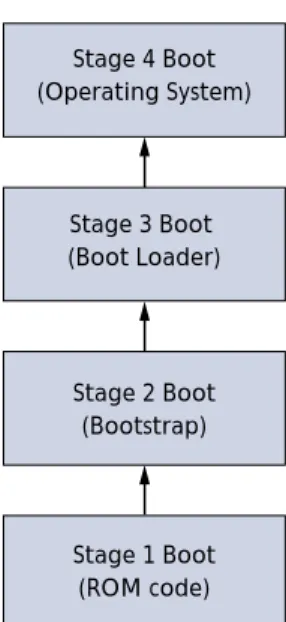
The boot sequence for a 32-bit ARM processor-based system involves the four steps shown in Figure 2.
• Stage 1: ROM code initializes the e-MMC device and copies (or shadows) the code for stage 2 from the e-MMC device to RAM. The ROM code then jumps to the RAM memory location containing the first instruction of the stage 2 code.
• Stage 2: Code runs in RAM. It bootstraps the system by shadowing the stage 3 boot-loader code from the e-MMC device to RAM. The stage 2 code then jumps to the RAM memory location containing the first instruction of the stage 3 code.
• Stage 3: Code also runs in RAM. It shadows the OS code from the e-MMC device to RAM. The stage 3 code then jumps to the RAM memory location containing the first instruction in the OS.
• Stage 4: The OS takes control of the system.
Figure 2: Boot Sequence
Three Methods for Accomplishing Stages 1–4
System designers have several methods available to them for initializing the e-MMC device and starting the transfer of boot code from the device. These methods are depen-dent on the specification and commands supported by Micron’s e-MMC device. They include:
• Boot method for e-MMC devices supporting MMCA Specification version 4.2. • Boot method for e-MMC devices supporting MMCA Specification version 4.3, MMC
Boot Sequence Option 1.
• Boot method for e-MMC devices supporting MMCA Specification version 4.3, MMC Boot Sequence Option 2.
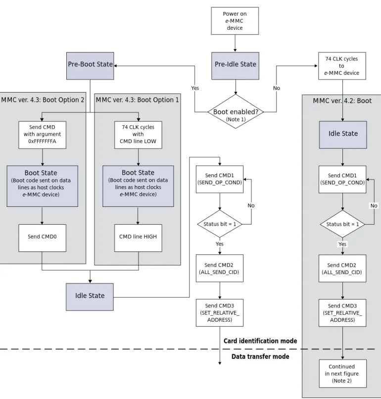
Figure 3 on page 4 defines the necessary steps required to accomplish booting from Micron’s e-MMC embedded memory for each of these three methods.
Stage 4 Boot (Operating System)
Stage 3 Boot (Boot Loader)
Stage 2 Boot (Bootstrap)
Stage 1 Boot (ROM code)
e-MMC Boot Sequence for 32-Bit ARM Processors
Figure 3: Boot from e-MMC DeviceNotes: 1. Enable via extended CSD register, byte 179 (see Table 2 on page 7). 2. This figure is continued in Figure 4 on page 5.
74 CLK cycles with CMD line LOW
74 CLK cycles to e-MMC device Power on e-MMC device Idle State Idle State
Pre-Boot State Pre-Idle State
MMC ver. 4.3: Boot Option 2 MMC ver. 4.3: Boot Option 1 MMC ver. 4.2: Boot
Boot State
(Boot code sent on data lines as host clocks
e-MMC device)
CMD line HIGH Send CMD
with argument 0xFFFFFFFA
Boot State
(Boot code sent on data lines as host clocks
e-MMC device)
Send CMD0
Send CMD1 (SEND_OP_COND)
Status bit = 1
Send CMD2 (ALL_SEND_CID)
Send CMD3 (SET_RELATIVE_
ADDRESS)
Card identification mode Data transfer mode
No Boot enabled? (Note 1) No Yes Yes Send CMD1 (SEND_OP_COND)
Status bit = 1
Send CMD2 (ALL_SEND_CID)
Continued in next figure
(Note 2) Send CMD3 (SET_RELATIVE_ ADDRESS) No Yes
e
-MMC Devices Supporting MMCA Specification ver. 4.2
MMCA version 4.2 e-MMC devices include support for 52 MHz operation and support densities greater than 2GB. While these devices do not have a specific boot mode, they can support boot operations via the method described below.
e
-MMC Initialization and Data Transfer
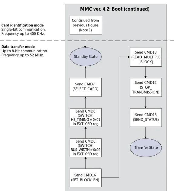
Before the boot code can be read from the device and copied into RAM for execution, the host system must initialize the e-MMC device with a series of commands. Figure 4 shows the boot code data transfer steps for version 4.2 e-MMC devices. The commands are described in Table 4 on page 12 and Table 5 on page 13.
Figure 4: e-MMC ver. 4.2 Boot: Data Transfer Mode
Notes: 1. See Figure 3 on page 4.
Transfer State Standby State
Send CMD6 (SWITCH) BUS_WIDTH = 0x02
in EXT_CSD reg Send CMD6
(SWITCH) HS_TIMING = 0x01
in EXT_CSD reg Send CMD7 (SELECT_CARD)
Send CMD16 (SET_BLOCKLEN)
Send CMD12 (STOP_ TRANSMISSION)
Send CMD13 (SEND_STATUS)
Send CMD18 (READ_MULTIPLE
_BLOCK) Continued from
previous figure (Note 1)
Card identification mode
Single-bit communication. Frequency up to 400 KHz.
Data transfer mode
Up to 8-bit communication. Frequency up to 52 MHz.
e-MMC Devices Supporting MMCA Specification ver. 4.3
e
-MMC Devices Supporting MMCA Specification ver. 4.3
The MMCA Specification 4.3-compliant devices are backward compatible and support MMCA Specification version 4.2 boot methods described previously. They also offer a simpler approach to reading boot code from the device, and either of two options can be used.
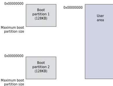
Version 4.3 e-MMC devices are equipped with two 128KB boot partitions; each is sepa-rated from the user data partition. The boot partitions cannot be addressed using normal MMC commands (see Figure 5). The system can be configured to boot from either boot partition using byte 179 of the extended CSD register (see Table 2 on page 7 for details).
Figure 5: e-MMC Boot Partitions
User area Boot
partition 1 (128KB)
Boot partition 2
(128KB)
0x00000000 0x00000000
Maximum boot partition size
Maximum boot partition size 0x00000000
The bus width of the e-MMC device can be configured using byte 177 of the Extended CSD register (see Table 3).
Table 2: Boot Partition Enable: Extended CSD Register Byte 179
Bit Field Value Description
7 Reserved
6 BOOT_ACK (nonvolatile) 0x0 No boot acknowledge sent (default)
0x1 Boot acknowledge sent during boot operation [5:3] BOOT_PARTITION_ENABLE (non-volatile). User selects boot data that will be sent to host
0x0 Device not boot enabled (default) 0x1 Boot partition 1 enabled for boot 0x2 Boot partition 2 enabled for boot 0x3–0x6 Reserved
0x7 User area enabled for boot [2:0]: BOOT_PARTITION_ACCESS. User selects boot partition for read and write operation
0x0 No access to boot partition (default) 0x1 R/W boot partition 1
0x2 R/W boot partition 2 0x3–0x7 Reserved
Table 3: Bus Width Setting for Boot Operations: Extended CSD Register Byte 177
Bit Field Value Description
[7:3] Reserved
2 RESET_BOOT_BUS_WIDTH (nonvolatile) 0x0 Reset bus width to x1 after boot operation (default) 0x1 Retain boot bus width after boot operation
[1:0] BOOT_BUS_WIDTH (nonvolatile)
0x0 x1 bus width in boot operation mode (default) 0x1 x4 bus width in boot operation mode
0x2 x8 bus width in boot operation mode 0x3 Reserved
e-MMC Devices Supporting MMCA Specification ver. 4.3
e
-MMC ver. 4.3 Boot Option 1
Details for implementing boot sequence option 1 include:
• The required boot-sequence steps shown in Figure 3 on page 4 for version 4.3 e-MMC devices.
• If the host sends any normal MMC commands before initiating boot, the device will be locked out of boot mode until the next power cycle.
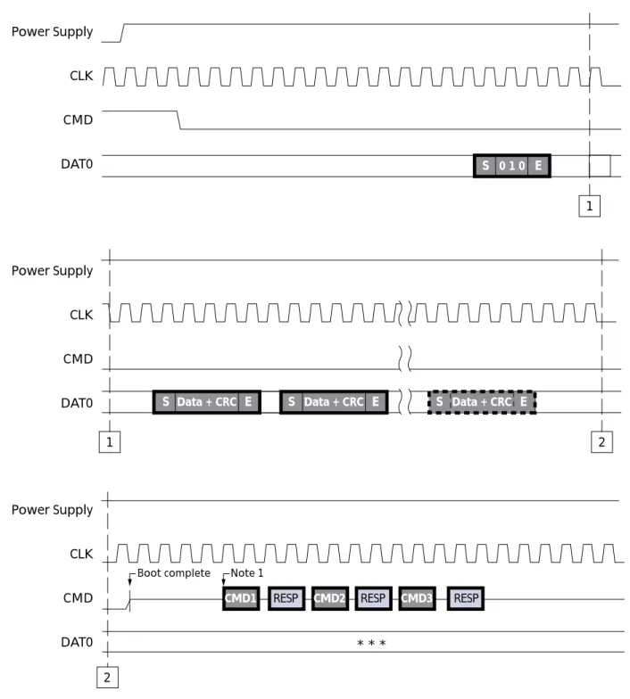
• Immediately after power-up, the host must hold the MMC CMD line LOW for 74 clock cycles. This tells the e-MMC device to access its boot partition.
• The host does not need to provide an address for the boot partition.
• If boot acknowledge is enabled, the e-MMC device responds to the CMD line LOW with a boot acknowledge pattern of “010” if it is bootable.
• There is a maximum of 50ms (typically 25ms) from CMD line LOW to boot acknowl-edge on DAT[0].
• The host can now read boot code in boot partition by clocking the e-MMC device. • Boot operation is terminated by CMD line HIGH or all contents of enabled boot
parti-tion are sent to host.
• A minimum of 56 clocks are required after terminating boot.
• The device returns to open-drain mode at the end of boot (CMD line driver only). • See Figure 6 on page 9 for additional details.
Figure 6: MMC Specification ver. 4.3 Boot Sequence Option 1
Notes: 1. MIN: 8 clocks + 48 clocks = 56 clocks required from CMD line HIGH to next MMC command.
Power Supply CLK CMD DAT0
Power Supply CLK CMD DAT0
Power Supply CLK CMD DAT0
CMD1 RESP CMD2 RESP CMD3 RESP
S 0 1 0 E
Note 1
* * * 2
1
2 1
S Data + CRC E S Data + CRC E S Data + CRC E
e-MMC Devices Supporting MMCA Specification ver. 4.3
e
-MMC ver. 4.3 Boot Option 2
Details for implementing boot sequence option 2 include:
• The required boot sequence steps shown in Figure 3 on page 4 for e-MMC version 4.3 devices.
• If the host sends any normal MMC commands before initiating boot, the device will be locked out of boot mode until the next power cycle.
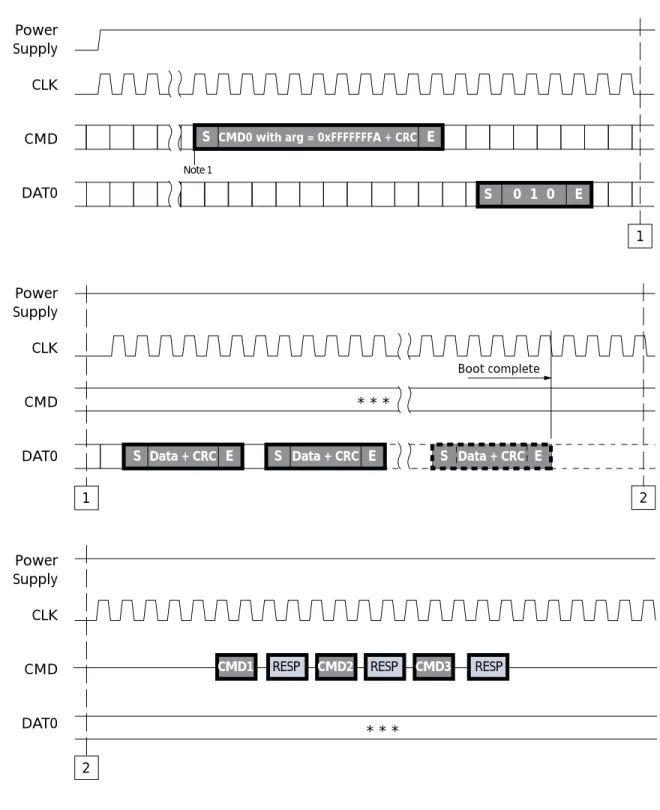
• Immediately after power-up, the host sends CMD 0 with argument 0xFFFFFFFA to tell the e-MMC device to access the boot partition.
• If boot acknowledge is enabled, the e-MMC device responds to the CMD line LOW with a boot acknowledge pattern of “010” if it is bootable.
• The host can now read boot code in the boot partition by clocking the e-MMC device. • There is a maximum of 1 second from the end bit of CMD0 to the start of boot data on
the DAT line(s).
• Boot operation is terminated only by the host sending CMD0 RESET or all contents of the enabled boot partition sent to host.
Figure 7: MMC Specification ver. 4.3 Boot Sequence Option 2
Notes: 1. After power is stable, a minimum of 74 clocks are required before issuing the boot com-mand start bit.
Power Supply CLK
CMD
DAT0
Power Supply CLK
CMD
DAT0
Power Supply CLK
CMD
DAT0
CMD0 with arg = 0xFFFFFFFA + CRC E
S S
0 1 0 E
S Data + CRC E Note 1
* * *
Data + CRC E
S S Data + CRC E
1
1
CMD1 RESP CMD2 RESP CMD3 RESP
* * * 2
2
Verifying Boot Code in e-MMC ver. 4.3
Verifying Boot Code in
e
-MMC ver. 4.3
To verify boot code after it is programmed into the e-MMC device, use the following process:
• The host sends a SELECT command to put the device into transfer state.
• The host sends a SWITCH command to set BOOT_PARTITION_ACCESS[2:0] bits in extended CSD byte[179].
• The host reads boot data using a single- or multiple-block READ command with the specific addressing mode supported by the device; i.e., byte addressing or sector addressing.
• The host sends a SWITCH command to clear BOOT_PARTITION_ACCESS[2:0] bits in extended CSD byte[179].
Command Definitions and Registers
Tables 4–6 provide the command definitions and registers designers will need to correctly implement an e-MMC embedded memory device in their designs.
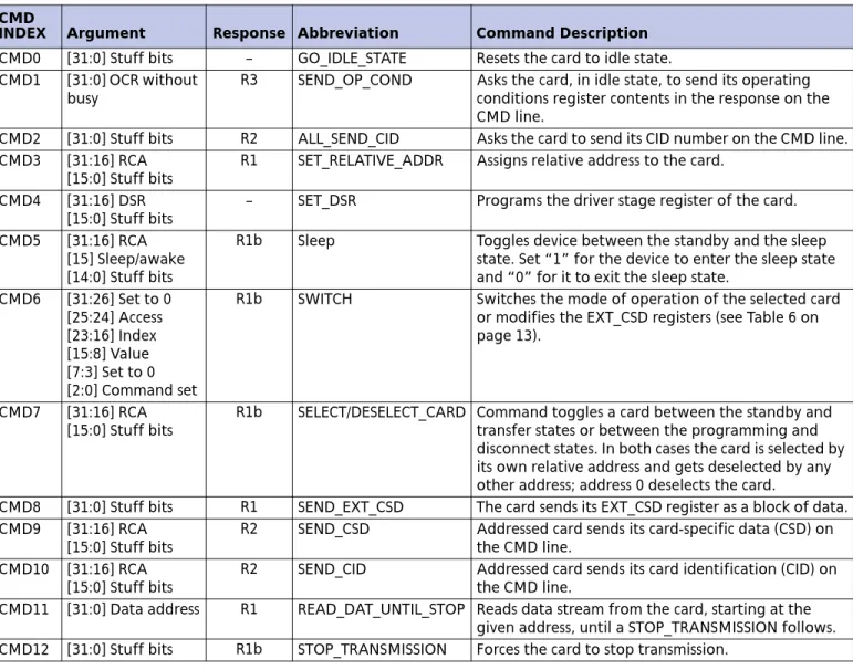
Table 4: MMC Basic Commands CMD
INDEX Argument Response Abbreviation Command Description
CMD0 [31:0] Stuff bits – GO_IDLE_STATE Resets the card to idle state. CMD1 [31:0] OCR without
busy
R3 SEND_OP_COND Asks the card, in idle state, to send its operating conditions register contents in the response on the CMD line.
CMD2 [31:0] Stuff bits R2 ALL_SEND_CID Asks the card to send its CID number on the CMD line. CMD3 [31:16] RCA
[15:0] Stuff bits
R1 SET_RELATIVE_ADDR Assigns relative address to the card.
CMD4 [31:16] DSR [15:0] Stuff bits
– SET_DSR Programs the driver stage register of the card.
CMD5 [31:16] RCA [15] Sleep/awake [14:0] Stuff bits
R1b Sleep Toggles device between the standby and the sleep state. Set “1” for the device to enter the sleep state and “0” for it to exit the sleep state.
CMD6 [31:26] Set to 0 [25:24] Access [23:16] Index [15:8] Value [7:3] Set to 0 [2:0] Command set
R1b SWITCH Switches the mode of operation of the selected card or modifies the EXT_CSD registers (see Table 6 on page 13).
CMD7 [31:16] RCA [15:0] Stuff bits
R1b SELECT/DESELECT_CARD Command toggles a card between the standby and transfer states or between the programming and disconnect states. In both cases the card is selected by its own relative address and gets deselected by any other address; address 0 deselects the card.
CMD8 [31:0] Stuff bits R1 SEND_EXT_CSD The card sends its EXT_CSD register as a block of data. CMD9 [31:16] RCA
[15:0] Stuff bits
R2 SEND_CSD Addressed card sends its card-specific data (CSD) on the CMD line.
CMD10 [31:16] RCA [15:0] Stuff bits
R2 SEND_CID Addressed card sends its card identification (CID) on the CMD line.
CMD13 [31:16] RCA [15:0] Stuff bits
R1 SEND_STATUS Addressed card sends its status register.
CMD14 [31:0] Stuff bits R1 BUSTEST_R A host reads the reversed bus testing data pattern from a card.
CMD15 [31:16] RCA [15:0] Stuff bits
– GO_INACTIVE_STATE Sets the card to inactive state.
CMD19 [31:0] Stuff bits R1 BUSTEST_W A host sends the bus test data pattern to a card.
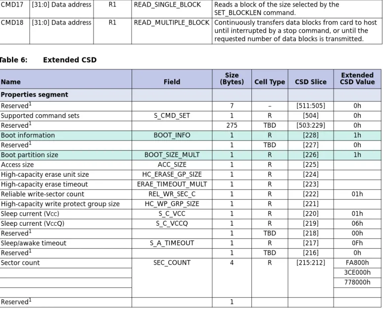
Table 5: MMC Block-Oriented Read Commands CMD
INDEX Argument Response Abbreviation Command Description
CMD16 [31:0] Block length R1 SET_BLOCKLEN Sets the block length (in bytes) for all following block commands (READ and WRITE). Default block length is specified in the CSD.
CMD17 [31:0] Data address R1 READ_SINGLE_BLOCK Reads a block of the size selected by the SET_BLOCKLEN command.
CMD18 [31:0] Data address R1 READ_MULTIPLE_BLOCK Continuously transfers data blocks from card to host until interrupted by a stop command, or until the requested number of data blocks is transmitted.
Table 6: Extended CSD
Name Field (Bytes)Size Cell Type CSD Slice CSD ValueExtended
Properties segment
Reserved1 7 – [511:505] 0h
Supported command sets S_CMD_SET 1 R [504] 0h
Reserved1 275 TBD [503:229] 0h
Boot information BOOT_INFO 1 R [228] 1h
Reserved1 1 TBD [227] 0h
Boot partition size BOOT_SIZE_MULT 1 R [226] 1h
Access size ACC_SIZE 1 R [225]
High-capacity erase unit size HC_ERASE_GP_SIZE 1 R [224] High-capacity erase timeout ERAE_TIMEOUT_MULT 1 R [223]
Reliable write-sector count REL_WR_SEC_C 1 R [222] 01h High-capacity write protect group size HC_WP_GRP_SIZE 1 R [221]
Sleep current (VCC) S_C_VCC 1 R [220] 01h
Sleep current (VCCQ) S_C_VCCQ 1 R [219] 06h
Reserved1 1 TBD [218] 00h
Sleep/awake timeout S_A_TIMEOUT 1 R [217] 0Fh
Reserved1 1 TBD [216] 0h
Sector count SEC_COUNT 4 R [215:212] FA800h
3CE000h 778000h
Reserved1 1
Table 4: MMC Basic Commands (continued) CMD
Command Definitions and Registers
Notes: 1. Reserved bits should be read as “0.” Minimum write performance for 8-bit at
52 MHz
MIN_PERF_W_8_52 1 R [210]
Minimum read performance for 8-bit at 52 MHz
MIN_PERF_R_8_52 1 R [209]
Minimum write performance for 8-bit at 26 MHz and 4-bit at 52 MHz
MIN_PERF_W_8_26_4_5 2
1 R [208]
Minimum read performance for 8-bit at 26 MHz and 4-bit at 52 MHz
MIN_PERF_R_8_26_4_52 1 R [207]
Minimum write performance for 4-bit at 26 MHz
MIN_PERF_W_4_26 1 R [206]
Minimum read performance for 4-bit at 26 MHz
MIN_PERF_R_4_26 1 R [205]
Reserved 1 TBD [204]
Power class for 26 MHz at 3.6V PWR_CL_26_360 1 R [203] 00h Power class for 52 MHz at 3.6V PWR_CL_52_360 1 R [202] 00h Power class for 26 MHz at 1.95V PWR_CL_26_195 1 R [201] 00h Power class for 52 MHz at 1.95V PWR_CL_52_195 1 R [200] 00h
Reserved1 3 [199:197] 0h
Card type CARD_TYPE 1 R [196] 3h
Reserved1 1 TBD [195] 0h
CSD structure version CSD_STRUCTURE 1 R [194] 2h
Reserved1 1 TBD [193] 0h
Extended CSD revision EXT_CSD_REV 1 R [192] 3h
Modes Segment
Command set CMD_SET 1 R/W [191] 0h
Reserved1 1 [190] 0h
Command set revision CMD_SET_REV 1 RO [189] 0h
Reserved1 1 [188] 0h
Power class POWER_CLASS 1 R/W [187] 0h
Reserved1 1 [186] 0h
High-speed interface timing HS_TIMING 1 R/W [185] 0h
Reserved1 1 [184] 0h
Bus width mode BUS_WIDTH 1 WO [183] 0h
Reserved1 1 [182] 0h
Erased memory content ERASED_MEM_CONT 1 RO [181] 0h
Reserved1 1 [180] 0h
Boot configuration BOOT_CONFIG 1 R/W [179] 0h
Reserved1 1 [178] 0h
Boot bus width1 BOOT_BUS_WIDTH 1 R/W [177] 0h
Reserved1 1 [176] 0h
High-density erase group definition ERASE_GROUP_DEF 1 R/W [175] 0h
Reserved1 175 [174:0] 0h
Table 6: Extended CSD (continued)
Name Field
Size
(Bytes) Cell Type CSD Slice
Extended CSD Value
®
8000 S. Federal Way, P.O. Box 6, Boise, ID 83707-0006, Tel: 208-368-3900 [email protected] www.micron.com Customer Comment Line: 800-932-4992
Micron, the M logo, and the Micron logo are trademarks of Micron Technology, Inc.All other trademarks are the property of their respective owners.
Summary
MMC devices provide low-cost, high-performance, industry-standard data storage media for many mobile applications. These devices free the host processor from routine tasks such as wear leveling and error correction. By enabling systems to boot from MMC, designers can use an MMC device as a single, nonvolatile memory source, thus reducing costs and achieving higher performance than they can obtain from other data storage options.
Revision History
Revision History
Rev. C . . . 6/08
• Product name changed from Managed NAND to e-MMC embedded memory.
Rev. B . . . .10/07
Rev. A . . . 8/07
![Figure 1: MMC Bus R OD R DAT R CMD CMD DAT[7:0] CLKMMCHost MMC Device](https://thumb-us.123doks.com/thumbv2/123dok_us/8502844.2275261/2.918.252.799.531.984/figure-mmc-bus-dat-cmd-cmd-clkmmchost-device.webp)