http://www.sciencepublishinggroup.com/j/eas doi: 10.11648/j.eas.20190402.11
ISSN: 2575-2022 (Print); ISSN: 2575-1468 (Online)
Numerical Simulation of Centrifugal Pump and Effect of
Impeller Geometry on Its Performance
Mohamed Hassan Gobran
1, Mostafa Mohamed Ibrahim
1, *, Ramy
Elsayed
Shaltout
1,
Mahmoud Ahmed Shalaby
21Mechanical Power Engineering Department, Faculty of Engineering, Zagazig University, Zagazig, Egypt 2
Jushi Egypt for Fiberglass Industry S.A.E, Port Said, Egypt
Email address:
*
Corresponding author
To cite this article:
Mohamed Hassan Gobran, Mostafa Mohamed Ibrahim, Ramy Elsayed Shaltout, Mahmoud Ahmed Shalaby. Numerical Simulation of Centrifugal Pump and Effect of Impeller Geometry on Its Performance. Engineering and Applied Sciences. Vol. 4, No. 2, 2019, pp. 21-29. doi: 10.11648/j.eas.20190402.11
Received: April 2, 2019; Accepted: May 15, 2019; Published: June 4, 2019
Abstract:
In the presented paper, the effect of impeller geometric parameters on the performance of centrifugal pump has been investigated. This study was performed for different flow rates and rotational speeds, allowing to obtain the performance curve for the centrifugal pump. Three dimensional computational fluid dynamic simulation of the impeller and volute for a centrifugal pump has been performed using ANSYS CFX software (a high-performance computational fluid dynamics software tool that delivers reliable and accurate solutions). The pump has an outside impeller diameter of 205 mm, impeller outlet width of 16 mm, rotational speed 1450 rpm, seven impeller blade and a specific speed of 28. By increasing the impeller outer diameter and outlet width, both net head and power consumed are increased. In addition, it was noticed that the best efficiency point (BEP) was achieved at volume flow rate higher than design flow rate. The performed simulations indicated that; by changing the impeller outer diameter from 200 mm to 210 mm, the flow rate of BEP increases about by 14.7%. By changing the impeller outlet width from 14 mm to 18 mm, the flow rate of BEP increased by about 9%, and the efficiency of BEP reduced by approximately 0.5%. It was also noticed that, increasing the rotational speed will cause an increase in the net head and consumed power. An increase of 13.8% for the flow rate of BEP was observed when changing the rotational speed from 1400 rpm to 1500 rpm, with the same BEP.Keywords:
Centrifugal Pump, Impeller Diameter, Rotational Speed, Impeller Width1. Introduction
In recent years, centrifugal pump have been increasingly utilized for various purposes, such as irrigation, water supply, steam power plants, oil refineries, air conditioning systems. Due to the vast application it is very important that centrifugal pump should work efficiently. Studies by the United States Department of Energy/Lawrence Berkeley National Laboratory and the European Commission show that more than 20% of the global motor electrical energy consumption is consumed by pumps. It was illustrated that pumps consume 22% of the industrial energy consumption, hence it presents an area which has great energy saving potential [1].
Based on the main pioneering researches on the centrifugal pump, the performance as a function of impeller geometry was investigated, and the obtained results were used for the design and selection of these pumps
Li investigated experimentally and numerically the effect of fluid viscosity on the performance of centrifugal oil pumps [2-7]. Based on his results, the high viscosity leads to rapid increase in the disc friction losses over outside of the impeller shroud and hub. The viscosity of fluid causes a flow reduction in the impeller and volute. Furthermore, Li found that there is a wide wake near the blade suction side of the centrifugal pump impeller. The optimum number was obtained of blades for the impeller when fluids with different viscosities are pumped.
tools. Their method was based on the geometrical design and the performance analysis [8]. Their design tool took into account models and correlations resulting from experimental data dealing with many ranges of industrial centrifugal pumps which constitute a significant database.
Kergourlay et al. investigated numerically the effect of separated blades on the flow field of water in centrifugal pumps [9]. The presence of the spiltters increases the head rise compared to the original impeller due to the increase of the impeller slip factor which helps conduction of the flow.
An experimental and numerical study was carried out by Shojaeefard et al. on the effect of the impeller blade’s outlet angle of the centrifugal pump [10, 11]. When the blade outlet angle increases, the width of wake at the outlet of impeller decreases. This observed phenomenon causes an improvement in centrifugal pump performance when handling viscous fluids.
Grepsas et al. investigated numerically the impeller blade design in centrifugal pumps by dynamic algorithm [12]. They obtained flow analysis was used to conduct parametric studies of the effect of some geometric parameters of a centrifugal pump impeller. Their results showed that their modifications could have a significant impact on its performance.
The numerical analysis carried out by Spence and Amaral-Teixeira investigated the geometrical variations on the pressure pulsations and performance characteristics of a centrifugal pump [13]. Their results concentrated on selected locations around the pump and provided the detailed information regarding the pressure pulsation close to the impeller outlet, in the volute and in the leakage flow region.
Cheah et al. investigated numerically the internal flow in a centrifugal pump having an impeller with six twisted blades by using a three-dimensional Navier-Stokes code with a standard k−ε two-equation turbulence model [14]. A
detailed analysis of the results at design load,
(
Q
design)
, andoff-design conditions,
(
Q=0.43 Qdesign and Q=1.45 Qdesign)
,were presented. Their results showed that the impeller passage flow at design point is quite smooth and follows the curvature of the blade. When operating at off-design load, the flow pattern has changed significantly from the well-behaved flow pattern at design load condition.
The performance of a centrifugal pump with a five blade impeller was numerically investigated by Guleren and Pinarbasi at low rotating speed of 890 rpm [15]. The k−ε
turbulence model has been used in computational used by Guleren. Flow characteristics were assumed to be stalled in the appropriate region of flow rate levels of 1.31–2.86 L/s. Being below design conditions, there is a consistent high-speed leakage flow in the gap between the impeller and the diffuser from the exit side of the diffuser to the beginning of the volute.
Asuaje et al. performed a 3D-CFD simulation of impeller and volute of a centrifugal pump using CFX code with a specific speed of 32 [16]. The flow simulation was carried out for several impeller blades and volute tongue relative
positions. The velocity and pressure field were calculated for different flow rates, allowing to obtain the radial thrust on the pump shaft.
Spalart-Allmaras on equation turbulence model has been used by Cui et al. to numerically investigate the effect of number of splitting blades on the flow characteristics using long, mid and short blades [17]. The relative velocity distribution, pressure distribution and static pressure rise at the design point were obtained for the regular impeller with only long blades and three complex impellers with long, mid or short blades.
Anagnostopoulos simulated 3D turbulent flow in a radial pump impeller for a constant rotational speed of 1500 rpm using standard k−ε turbulence model [18]. A number of geometric variables are introduced for the parameterization of the impeller
geometry allowing also for easy design modifications. They presented the characteristic performance curves for the entire load range of the impeller are constructed, and their pattern is found reasonable and in agreement with theory.
Anagnostopoulos developed numerical methodology to simulate the turbulent flow in a 2D centrifugal pump impeller using the k−ε turbulence model [19]. The predicted overall efficiency curve of the pump was found to agree very well with the corresponding experimental data. The developed numerical optimization algorithm was combined with the evaluation software in order to find the impeller geometry that maximizes the pump efficiency, using as free design variables the blade angles at the leading and the trailing edge.
The effect of various geometrical parameters on improving the performance of centrifugal pump was numerically investigated by Bacharoudis et al. [20]. It was concluded that, by increasing the blade angle, the performance curve becomes smoother and flatter for the whole range of the flow rates. When pump operated at nominal capacity, the gain in the head is more than 6% when the outlet blade angle increases from 200 to 500.
Weidong et al. investigated numerically the effect of impeller outlet width on performance of deep well centrifugal pump [21]. The performance results indicted that the oversize impeller outlet width leads to poor pump performances and increasing shaft power. The proposed research enhances the theoretical basis of pump design to improve the performance and reduce the manufacturing cost of deep-well centrifugal pump.
Singh et al. investigated numerically the relationships among the impeller eye diameter, vane exit angle and width of the blade at exit [22]. Different pump models were studied by varying critical design parameters to different levels. Optimal pump design is formulated using Response surface method. The objective functions were defined as the total head and the total efficiency at the design flow-rate.
pump test rig. Five main impeller geometric characteristics were chosen as the research target to carry out the orthogonal experiment. The best programs for pump efficiency and head were obtained through the variance analysis method. The results demonstrated that the impeller outlet width has the largest effect on both pump efficiency and head.
Mentzos et al. investigated numerically the complex internal flows in water pump impellers, thus facilitating the design of pumps [24]. The commercial three-dimensional Navier-Stokes code Fluent, with a standard k−ε
turbulence model was used to simulate the problem under examination. The calculation predicted the flow pattern and the pressure distribution in the untwisted blade passages and the overall performances and the head-capacity curve were discussed.
The current work is numerical investigates the effect of impeller geometry on the centrifugal pump performance.
2. Physical Model
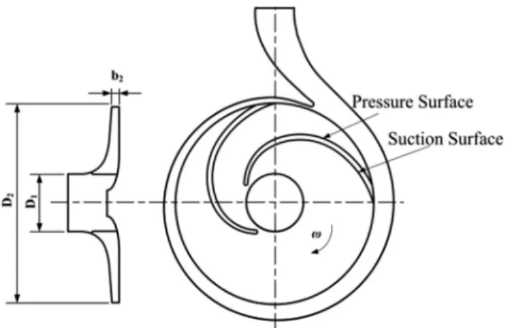
Three-dimensional (3D) single-stage and single-suction centrifugal pump was employed. The centrifugal pump design parameters are as follows: flow rate Q=52.5 m h3 , head H=12.75 m , rotating speed N =1450 rpm , and specific speed ns=28. Figure 1 shows the centrifugal pump main dimensions. Table 1 shows the main geometric parameters of the centrifugal pump.
Figure 1. Centrifugal pump main dimensions.
Table 1. Main geometric parameters of the centrifugal pump.
Parameter Value
1
D 109 mm
2
D 205 mm
2
β 270
b 16 mm
Z 7
3. Computational Model
3.1. Fundamental Equations
The fundamental equations are employed to describe the flow characteristics in the centrifugal pump, which
include two main parts: continuity equation and motion equation, corresponding with mass conservation law and momentum conservation law.
(
i)
0i
u
t x
∂
∂ + =
∂ ∂
ρ ρ
(1)
2 3
j j
i i i
j i
j i j j i i j
u u
u u p u
u f
t x x x x x x x
∂ ∂ ∂ + ∂ = −∂ + ∂ ∂ + − ∂
∂ ∂ ∂ ∂ ∂ ∂ ∂ ∂
ρ ρ ρ µ µ (2)
Where:
ρ
=The fluid densityu
=
The fluid velocityi
f
=
The body force p=The pressure=
µ
The fluid dynamic viscosity3.2. Turbulence Model
RNG K−
ε
turbulent model proposed by Yakhot and Orzag was employed to deal with turbulent flow [25]. In the centrifugal pump, the impeller is the rotating part whose rotation effects could be fully dealt by the turbulent dissipation rate( )
ε
equation in this turbulent model. On the other hand, the RNG K−ε
turbulent model has high-precision, which could guarantee the accuracy of the numerical results.( )
(
i)
(
)
k t k
i j j
ku
k k
G
t x x x
∂
∂ + = ∂ + ∂ + +
∂ ∂ ∂ ∂
ρ
ρ
α µ µ
ρε
(3)( )
(
)
2(
)
1 2
i
k t
i j j
u
C G C
t x k k x x
∂
∂ + = + ∂ + ∂
∂ ∂ ε ε ∂ ε ∂
ρε
ρε ε ρε α µ µ ε
(4)
2
t
k C = µ µ ρ
ε (5)
Where: k =The turbulent kinetic energy
=
ε
The turbulent dissipation ratet
=
µ
The turbulent viscosityk
G
=
The generation term of turbulent kinetic energy which is caused by the mean velocity gradient1
C
ε,C
2ε,α
k,α
ε,C
µ= Empirical coefficients1 1.42
Cε= C2ε =1.68 αk =1 .3 9 αε =1.39 Cµ =0 .0 9
3.3. Mesh Characteristics
field structure. This is because the flow field properties variation such as pressure and velocity at these regions are expected to be substantial. Figure 2 shows the meshes of the centrifugal impeller and the mesh assembly of the whole flow field.
Grid sensitivity test was performed using six mesh sizes of the to divide the grid of the model. The grid numbers are 280410, 410260, 512242, 614560, 718766, 810315 and 907472, were examined as indicated in Figure 3. The final mesh number used in the computational analysis in this paper was set to 810315.
Figure 2. Mesh sensitivity analysis.
Figure 3. Mesh of impeller and volute.
3.4. Boundary Conditions
Centrifugal pump impeller domain is considered as rotating frame of reference with a rotational speed. A standard k−ε turbulence model has been activated in the model solver. Non slip boundary conditions have been imposed over the impeller blades, hub and shroud. Inlet static pressure and outlet mass flow rate are given based on flow rate as boundary conditions. Convergence precision of residuals is considered as 10-5. Three dimensional incompressible Navier-Stokes equations are solved with Ansys-CFX Solver.
4. Results and Discussion
The developed numerical model is applied to reproduce the performance characteristic curves of the standard centrifugal pump. Different simulations were carried out for different flow rates changing from 30 to 64 m3/h.
The computed curves are drawn in Figures 4, 5 and 6 for the original centrifugal pump with parameters 1450 rpm, Impeller outer diameter 205 mm, Impeller blade thickness 5mm, impeller outlet width of 16 mm, and impeller outlet blade angle 270.
Figure 4 shows the H −Q curve for the centrifugal pump. It is clear that for the centrifugal pump by increasing the volume flow rate the net fluid head is decreased.
Figure 5 illustrates the P−Q curve for the centrifugal
pump. It is clear that for the centrifugal pump by increasing the volume flow rate the power consumed by the centrifugal pump is increased.
Figure 6 depicts the η−Q curve for the centrifugal
pump. It is clear that that the maximum overall efficiency is about 70.1% and is achieved for Q=52.5 m h3 .
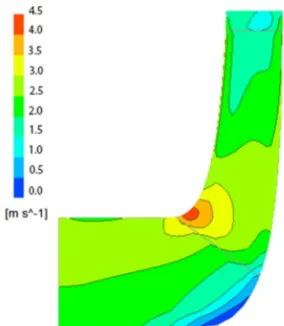
The velocity contours in the pump are plotted in Figure 7 for the impeller and volute at design flow rate
3 52.5
design
Q = m h. The volute tongue zone presents a strong recirculation of the fluid particles at the gap between the volute tongue and the impeller periphery.
Figure 8 demonstrates the pressure distribution within the impeller and volute casing when the pump is operating at design flow rate 52.5 3
design
Q = m h . The pressure increases gradually along streamwise direction within impeller blade-to-blade passage and has higher pressure on pressure surface than suction surface for each plane. However, the developed pressure inside the impeller and volute is not so uniform. The isobar lines are not all perpendicular to the pressure side of the blade inside the impeller passage, this indicated that there is a potential of flow separation because of the pressure gradient effect.
Figure 4. H−Qcurve. Volume Flow Rate [m3/h]
H
e
a
d
[m
]
30 35 40 45 50 55 60 65
Figure 5. P−Qcurve.
Figure 6. η −Q curve.
Figure 7. Velocity distribution inside impeller and volute.
Figure 8. Pressure distribution inside impeller and volute.
Volume Flow Rate [m3
/h]
P
o
w
e
r
[k
W
]
30 35 40 45 50 55 60 65
1.6 1.8 2 2.2 2.4 2.6 2.8 3
Volume Flow Rate [m3/h]
E
ff
ic
ie
n
c
y
[%
]
30 35 40 45 50 55 60 65
4.1. Effect of Impeller Diameter
In this section the effect of changing the impeller outer diameter on the centrifugal pump performance characteristic curves is introduced. The numerical simulation of the Centrifugal pump is carried out for different flow rates changing from 30 to 64 m3/h. The obtained performance curves are plotted for centrifugal pump with parameters; rotational speed 1450 rpm, Impeller blade thickness 5mm, impeller outlet width of 16 mm, and impeller outlet blade angle 270. The impeller outer diameter has different values of 200, 205, 210 mm.
Figure 9 shows the H −Q curve for the centrifugal pump. By increasing the volume flow rate, the net fluid head is decreased for the same impeller diameter. while, increasing the impeller outer diameter the net fluid head as well as the consumed power is increased.
Figure 10 shows the P−Q curve for the centrifugal
pump. It is noticed that by increasing the volume flow rate the power consumed by the centrifugal pump is increased for the same impeller diameter.
Figure 11 illustrates the η−Q curve for the centrifugal
pump. It is clear that that the best point efficiency is achieved for Qdesign =52.5 m3 hfor impeller diameter of 205mm. By increasing the impeller diameter the best point efficiency achieved at volume flow rate higher than Qdesign . By
increasing the impeller diameter the best efficiency point achieved at volume flow rate higher than Qdesign. The flow
rate and pump efficiency at BEP with different impeller diameter was summarized in Table 2. From 200 mm to 210 mm of impeller outlet diameter, the flow rate of BEP increased about by 14.7%, with the same BEP.
Table 2. Flow rate and efficiency at BEP for different impeller diameter.
Impeller Diameter (mm) 200 205 210
Flow Rate Q Qdesign 0.928 1 1.075
Efficiency, %η 70.10 70.10 70.10
Figure 9. H−Qcurvefor different impeller diameter.
Figure 10. P−Q curvefor different impeller diameter.
Figure 11. η −Qcurvefor different impeller diameter.
4.2. Effect of Rotational Speed
This section defines the effect of changing impeller rotational speed on the centrifugal pump performance characteristic curves. The computational analysis of Centrifugal pump is carried out for different flow rates changed from 30 to 64 m3/h. The computed curves are presented for centrifugal pump with parameters; impeller outer diameter 205 mm, Impeller blade thickness 5mm, impeller outlet width of 16 mm, and impeller outlet blade angle 270. The impeller rotational speed has different values of 1400, 1450, 1500 rpm.
Figure 1 demonstrates the H −Q curve for the centrifugal pump. For the defined centrifugal pump in this paper, by increasing the volume flow rate the net fluid head is decreased for the same rotational speed. By increasing the impeller rotational speed the net fluid head increases and the power consumed by the centrifugal pump is also increases.
Figure 13 shows the P−Q curve for the centrifugal pump. It is clear that for the centrifugal pump by increasing the volume flow rate the power consumed by
Volume Flow Rate [m3/h]
H
e
a
d
[m
]
25 30 35 40 45 50 55 60 65 70 10
10.5 11 11.5 12 12.5 13 13.5 14 14.5 15 15.5 16
D=210 mm D=205 mm D=200 mm
Volume Flow Rate [m3
/h]
P
o
w
e
r
[k
W
]
25 30 35 40 45 50 55 60 65 70 1.2
1.6 2 2.4 2.8 3.2 3.6 4
D=210 mm D=205 mm D=200 mm
Volume Flow Rate [m3/h]
E
ff
ic
ie
n
c
y
[%
]
25 30 35 40 45 50 55 60 65 70 58
60 62 64 66 68 70 72 74
the centrifugal pump is increased for the same impeller rotational speed..
Figure 14 depicts the η−Q curve for the centrifugal
pump. It is clear that that the best point efficiency is achieved for 52.5 3
design
Q = m h for impeller rotational speed of 1450 rpm. By increasing the impeller rotational speed the best point efficiency achieved at volume flow rate higher than Qdesign . By increasing the impeller
rotational speed the best point efficiency achieved at volume flow rate higher than Qdesign. The flow rate and
pump efficiency at BEP with different impeller rotational speed was summarized in Table 3. From 1400 rpm to1500 rpm of impeller rotational speed, the flow rate of BEP increased about by 13.8%, and the same BEP.
Table 3. Flow rate and efficiency at BEP for different rotational speed.
impeller rotational speed (rpm) 1400 1450 1500
Flow Rate Q Qdesign 0.932 1 1.070
Efficiency, %η 70.10 0.10 70.10
Figure 12. H−Qcurvefor different impeller rotational speed.
Figure 13. P−Q curvefor different impeller rotational speed.
Figure 14.η −Qcurvefor different impeller rotational speed.
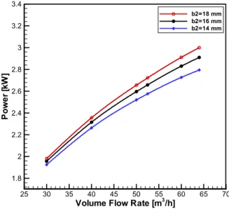
4.3. Effect of Impeller Outlet Width
In this section study the effect of Impeller outlet width on the centrifugal pump performance characteristic curves. Centrifugal pump is solved for different flow rates changing from 30 to 64 m3/h. The obtained performance curves are plotted for centrifugal pump with parameters; impeller outer diameter 205 mm, Impeller rotational speed, Impeller blade thickness 5mm, and impeller outlet blade angle 270. The impeller outlet width has different values of 14, 16, 18 mm.
Figure 15 presents the H −Q curve for the centrifugal
pump. It is clear that for the centrifugal pump by increasing the volume flow rate the net fluid head is decreased for the same impeller outlet width. By increasing the impeller outlet width the net fluid head is increased and the power consumed is also increased.
Figure 16 shows the P −Q curve for the centrifugal pump. It is clear thatthe power consumed by the centrifugal pump is increased, by increasing the volume flow rate for the same impeller outlet width..
Figure 17 defines the η−Q curve for the centrifugal
pump. It is clear that that the best point efficiency is achieved
for 3
52.5
design
Q = m h for impeller outlet width of 16mm. By increasing the impeller outlet width the best point efficiency achieved at volume flow rate higher than Qdesign.
By decreasing the impeller outlet width the best point efficiency achieved at volume flow rate lower than Qdesign.
The flow rate and pump efficiency at BEP with different impeller outlet width was summarized in Table 4. From 14 mm to18 mm of impeller outlet width, the flow rate of BEP increased about by 9%, and the efficiency of BEP reduced by 0.5% approximately.
Table 4. Flow rate and efficiency at BEP for different blade width.
Blade outlet width (mm) 14 16 18
Flow Rate Q Qdesign 0.96 1 1.05
Efficiency, %η 70.30 70.10 69.80
Volume Flow Rate [m3
/h]
H
e
a
d
[m
]
25 30 35 40 45 50 55 60 65 70 10
10.5 11 11.5 12 12.5 13 13.5 14 14.5 15 15.5 16
N=1500 rpm N=1450 rpm N=1400 rpm
Volume Flow Rate [m3
/h]
P
o
w
e
r
[k
W
]
25 30 35 40 45 50 55 60 65 70 1.2
1.6 2 2.4 2.8 3.2 3.6 4
N=1500 rpm N=1450 rpm N=1400 rpm
Volume Flow Rate [m3
/h]
E
ff
ic
ie
n
c
y
[%
]
25 30 35 40 45 50 55 60 65 70 58
60 62 64 66 68 70 72 74
Figure 15. H−Qcurve for different impeller outlet width.
Figure 16. P−Qcurvefor different impeller outlet width.
Figure 17. η −Qcurvefor different impeller outlet width.
5. Conclusions
From the numerical results and discussions for the effects of impeller parameters on the centrifugal pump performance, the following conclusions are drawn:
1. Both net fluid head and power consumed are increased with the increasing of impeller outer diameter.
2. By increasing the impeller diameter the best efficiency point achieved at volume flow rate higher than Qdesign .
When impeller diameter changes from 200 mm to 210 mm, the flow rate of BEP increased about by 14.7%, with the same BEP.
3. Both net fluid head and power consumed are increased with the increasing of the impeller rotational speed.
4. By increasing the impeller rotational speed the best point efficiency achieved at volume flow rate higher than
design
Q . When impeller rotational speed changes from 1400
rpm to1500 rpm, the flow rate of BEP increased about by 13.8%, and the same BEP.
5. Both net fluid head and power consumed are increased with the increasing of the impeller outlet width.
6. By increasing the impeller outlet width the best point efficiency achieved at volume flow rate higher than Qdesign.
When impeller outlet width changes fom 14 mm to18 mm, the flow rate of BEP increased about by 9%, and the efficiency of BEP reduced by 0.5% approximately.
Notation
b Impeller width (m) BEP Best Efficiency Point
CFD Computational Fluid Dynamic D1 Impeller inlet diameter (m) D2 Impeller outlet diameter (m) H Net fluid head
K Turbulent kinetic energy N Rotational Speed (rpm)
s
n
Specific speedQ Volume flow rate (m3 /h) Z Number of blades
t
µ
Turbulent viscosity (Pa.s)t
µ
Viscosity (Pa.s)ε
Turbulent dissipation rate1
β
Inlet blade angle (0)2
β
Outlet blade angle (0)References
[1] K. Rajput, "Textbook of fluid mechanics and hydraulic machines", Revised Edition, S.chand 2010.
[2] W. Li and Hu ZM, "An experimental study on performance of centrifugal oil pump", Fluids Mach 1997, 25(2), 3–7.
Volume Flow Rate [m3/h]
H
e
a
d
[m
]
25 30 35 40 45 50 55 60 65 70 10.5
11 11.5 12 12.5 13 13.5 14 14.5 15 15.5
b2=18 mm b2=16 mm b2=14 mm
Volume Flow Rate [m3/h]
P
o
w
e
r
[k
W
]
25 30 35 40 45 50 55 60 65 70
1.8 2 2.2 2.4 2.6 2.8 3 3.2 3.4
b2=18 mm b2=16 mm b2=14 mm
Volume Flow Rate [m3/h]
E
ff
ic
ie
n
c
y
[%
]
25 30 35 40 45 50 55 60 65 70
58 60 62 64 66 68 70 72 74
[3] W. Li and D. Deng, "Reynolds number of centrifugal oil pumps and its effects on the performance", Pump Technol 1999 (3), 3-10.
[4] W. Li, "Effects of viscosity of fluids on centrifugal pump performance and flow pattern in the impeller", International Journal of Heat and Fluid Flow, 2000, 2(21), 207–212.
[5] W. Li, " Numerical study on behavior of a centrifugal pump when delivering viscous oils – Part 1: Performance", International Journal of Turbo and Jet Engines, 2008, 25, 61-79.
[6] W. Li, "The sudden-rising head effect in centrifugal oil pumps", World Pumps, 2000, 149(2000), 34-36.
[7] W. Li, "Influence of the number of impeller blades on the performance of centrifugal oil pumps" World Pumps, 2002, 32–35.
[8] M. Asuaje, F. Bakir, S. Kouidri and R. Rey, "Inverse design method for centrifugal impellers and comparison with numerical simulation tools", International Journal of Computational Fluid Dynamics, 2004, 18(2), 101–110. [9] G. Kergourlay, M. Younsi, F. Bakir and R. Rey, "Influence
of splitter blades on the flow field of a centrifugal pump: Test-analysis comparison", International Journal of Rotating Machinery, 2007, Article ID 85024, 13 pages. [10] M. Shojaee, F. Boyaghchi and M. Ehghaghi, "Experimental
study and three dimensional numerical flow simulation in a centrifugal pump when handling viscous fluids", IUST International Journal of Engineering Science, 2006, 17(3-4), 53-60.
[11] M. Shojaee and F. Boyaghchi, "Studies on the influence of various blade outlet angles in a centrifugal pump when handling viscous", American Journal of Applied Sciences 2007, 4(9), 718–724.
[12] V. Grapsas, F. Stamatelos, JS. Anagnostopoulos, and D. Papantonis, "Numerical study and optimal blade design of a centrifugal pump by evolutionary algorithms", In: 12th International Conference, KES 2008 Zagreb, Croatia, September 3-5, 2008 Proceedings, 26-33.
[13] R. Spence and J. Teixeira, "A CFD parametric study of geometrical variations on the pressure pulsations and performance characteristics of a centrifugal pump", Computers & Fluids, 6 (38), 1243–1257.
[14] K. Cheah, T. Lee, S. Winoto and Z. Zhao, "Numerical flow simulation in a centrifugal pump at design and off-design conditions", International Journal of Rotating Machinery, 2007, Article ID 83641, 8 pages.
[15] K. Guleren and A. Pinarbasi, "Numerical simulation of the stalled flow within a vaned centrifugal pump", J. Mechanical Engineering Science, 2004, 425–435.
[16] M. Asuaje, F. Bakir, S. Kouidri, F. Kenyery and R. Rey, "Numerical modelization of the flow in centrifugal pump: volute influence in velocity and pressure fields", International Journal of Rotating Machinery 2005:3, 244– 255.
[17] C. Boaling, Z. Zuchao, Z. Jianci and C. Ying, "The flow simulation and experimental study of low-specific-speed high-speed complex centrifugal impellers', Chinese J. Chem. Eng., 2006, 14(4) 435-441.
[18] J. Anagnostopoulos, "Numerical calculation of the flow in a centrifugal pump impeller using Cartesian grid", Proceedings of the 2nd WSEAS Int. Conference on Applied and Theoretical Mechanics, Venice, Italy, November 20-22, 2006.
[19] J. Anagnostopoulos, A fast numerical method for flow analysis and blade design in centrifugal pump impeller", Journal of computer and fluid, 2008, pp 284-289.
[20] E. Bacharoudis, A. Filios, M. Mentzos and D. Margaris, “Parametric Study of a Centrifugal Pump Impeller by Varying the Outlet Blade Angle” The Open Mechanical Engineering Journal, 2008, 2, 75-83.
[21] S. Weidong, Z. Ling, L. Weigang, P. Bing, and L. Tao, “Numerical Prediction and Performance Experiment in a Deep well Centrifugal Pump with Different Impeller Outlet Width”, Chinese Journal Of Mechanical Engineering, 2013, 1 (26).
[22] R. Singh and M. Nataraj, “Parametric Study And Optimization Of Centrifugal Pump Impeller By Varying The Design Parameter Using Computational Fluid Dynamics: Part-I” Journal of Mechanical and Production Engineering (JMPE), 2012, 2(2), 87-97.
[23] L. Zhou and W. Shi “Performance Optimization In A Centrifugal Pump Impeller By Orthogonal Experiment And Numerical Simulation” Advances in Mechanical Engineering, 2013, Article ID 385809, 7 pages.
[24] M. Mentzos, A. Filios, M. Margarisp and D. Papanikas, “CFD prediction of flow through a centrifugal pump impeller,” 1st International Conference on Experiments/Process/System Modelling/Simulation/Optimization, 2005, Athens, 6-9 July, 1-8.