Abstract—Database design is an important activity in software development. EER diagram is one of diagrams, which is used in database design because EER diagram is a graphical representation and easy to understand between users and developers. Relational database constraints are important since database designers should consider when they design database. These constraints help database designers design database that meet, all user requirements. However, database designers cannot identify the constraints in the EER diagram. If database designers use the diagram without specifying constraints and transform it into relational database schema, the relational database schema may not meet all data requirements of users. This paper proposes a tool for generating database schema from EER diagram, written in XML format. The goals of this tool are transforming an EER diagram to relational database schema and allowing database designers specify relational database constraints in relation. The results of this tool are relational database schema with constraints according to user requirements, database schema, and data dictionary.
Index Terms—EER diagram, Relational database constraints, EER to relational mapping
I. INTRODUCTION
ECENTLY, database applications have become widespread in several enterprises, banks, universities, and hospitals. These database applications help them collect and access their data easily and correctly. Therefore, each application should be designed to meet all user requirements. The first step of database design is to collect and analyze user requirements. The second step is conceptual design that database designers need to define entities, attributes, relationships, and relational database constraints. The third step is logical design and the result of this step is relational database schema. The last step is physical database design.
Entity relationship (ER) diagram has become a popular diagram for database design because it is a graphical representation and easy to understand between database designers and users. ER diagram [1] consists of entities, attributes, and relationships. Extended Entity Relationship (EER) diagram [2] has all ER diagram concepts and has concepts of superclasses, subclasses, specializations, and
Manuscript received December 03, 2011; revised January 09, 2012. Lisa Simasatitkul is with Department of Computer Engineering, Faculty of Engineering, Chulalongkorn University, Bangkok Thailand (e-mail: [email protected])
Taratip Suwannasart is with Department of Computer Engineering, Faculty of Engineering, Chulalongkorn University, Bangkok Thailand (e-mail: [email protected])
generalizations. This diagram is developed to support complex software applications. However, database designers cannot specify constraints in ER and EER diagram, so they have to specify these constraints in relational tables later. The aim of this paper is to present a tool for generating relational database schema from EER diagram, written in XML format. This tool allows database designers to identify relational database constraints in any relation. Such constraints are entity integrity constraint, domain constraint, and referential integrity constraint. The rest of this paper is divided into seven sections. Section 1 is introduction. Section 2 is related work. Section 3 describes EER to relational mapping and relational database constraints. Section 4 shows architecture of our tool. Section 5 is the features of our tool. Case studies are shown in Section 6. The last section, we conclude our work.
II. RELATED WORK
A. ERDraw: An XML-based ER- diagram Drawing and Translation Tool
This paper [3] presents an XML-based ER diagram drawing and translation tool, named ERDraw. The tool supports drawing ER diagrams and translating an ER diagram to relational database schema automatically. This paper focuses only on binary relationship types, but does not concern about specialization relationships. Therefore, the tool developed from this work cannot transform EER diagram to relational database schema.
B. A Java based Parser Software for Converting XML Documents to the ER Model and Relational Databases
This paper [4] presents a tool for converting XML documents and their data to an ER model and a relational database schema respectively. The tool also creates relational database schema in Access database. However, the tool does not support EER diagram, so it cannot convert EER diagram into relational database schema.
III. BACKGROUND
A. EER to Relational Mapping
There are nine steps of mapping an EER diagram to relational, proposed by Elmasri and Navathe [2] as follows:
Step 1 Mapping of Regular Entity. A relation is created for each regular entity and all the simple attributes of an entity is created. The primary key of relation is derived from key attribute of the entity.
A Tool for Generating Relational Database
Schema from EER Diagram
Lisa Simasatitkul and Taratip Suwannasart
Step 2 Mapping of Weak Entity. A relation is created for each weak entity and all the simple attributes of an entity is created. The primary key of relation is the combination of owners' primary key and the weak entity's partial key. The foreign key of relation is primary key of owner relation.
Step 3 Mapping of Binary 1: 1 Relationship Types.
Relations corresponding to the entity types that participating in 1:1 relationship are identified. Then, any relation with a foreign key is chosen. A foreign key of relation is a primary key of the other relation.
Step 4 Mapping of Binary 1: N Relationship Types.
Two relations are identified for each binary 1:N relationship. A foreign key of the relation at N-side contains the primary key of the relation at 1-side.
Step 5 Mapping of Binary M: N Relationship Types.
A new relation is created for each binary M: N relationship type. The primary keys and foreign keys of the new relation are the primary of each relation that corresponding to the entity types participated in M: N relationship.
Step 6 Mapping of N-ary Relationship Types. A new relation is created for each n-ary relationship type. The primary keys and foreign keys of the new relation are the primary key of each relation that corresponding to the entity types participated in n-ary relationship.
Step 7 Mapping of Multivalued attribute. A new relation is created for each multivalued attribute. The primary key of the new relation is the combination of the multivalued attribute that corresponding to multivalued attribute in the entity and a new attribute of the new relation.
Step 8 Mapping of Specialization types. In this step, a relation is created for each superclass and all the simple attributes of superclass are created. The primary key of superclass relation is derived from primary key of superclass. Next, a relation is created for each subclass and all the simple attributes of subclass are also created. The primary key of subclass relation is derived from primary key of superclass.
Step 9 Mapping of Union types.
There are 2 cases in this step. The first case, superclasses have the different primary keys. A relation is created for each superclass and subclass. All the simple attributes of superclass and subclass are created. The primary key of superclass relation is derived from primary key of superclass. Then, a new attribute is created for primary key of subclass relation.
The second case, superclasses has the same primary key. A relation is created for each superclass and subclass; all the simple attributes of superclass and subclass are also created. The primary key of superclass relation and subclass is derived from primary key of superclass relation.
B. Relational Database Constraints
Relational database constraints [5], [6] are constraints that database designers should specify at relational database. These constraints guarantee that data is correct and not redundancy. Relational database constraints consist of entity integrity constraint, domain constraint, and referential integrity constraint.
Entity integrity constraint specifies that a primary key should be in every table; the key must be a unique value and
cannot be null value.
Domain constraint considers association of possible value in every attribute. Possible constraints of "attributes" domain are data type, range of data, not null, unique, and default value.
Referential integrity constraint considers a foreign key attributes in a table. Values of a foreign key attributes are the same as the values of the primary key attributes of the parent relation. This tool focuses of the delete options and update options that are "on delete no action", "on delete cascade", "on delete set null", on delete set default", "on delete restrict", "on update no action", "on update cascade", "on update set null", "on update set default" and "on update restrict".
IV. ARCHITECTURE OF OUR TOOL
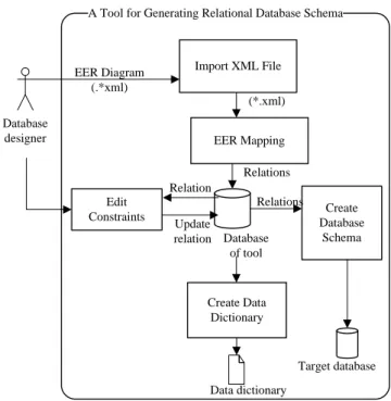
This paper we present a tool for generating a relational database schema from EER diagram, which is developed by Java language (JDK 6.0). This tool generates data dictionary and database schema, written in SQL script. The overall of architecture of the tool is shown in Fig. 1. This tool is composed of modules as follows:
A Tool for Generating Relational Database Schema
Import XML File EER Mapping Edit Constraints Create Data Dictionary Create Database Schema Database designer EER Diagram (.*xml) (*.xml) Relation Relations Update relation Relations Data dictionary Database of tool Target database
Fig. 1. An architecture of a tool
A. Importing XML File
The process of this module receives an EER diagram from database designers. The EER diagram written in XML should contain entities, attributes, and primary keys.
B. EER Mapping
XML file is separated into regular entities, weak entities, superclasses, subclasses, attributes, binary relationship types, specializations, unions, and primary keys. In this module, we use DOM (Document Object Model) to separate for each element. At first, we separate specialization
attribute, primary key and multivalued attribute respectively. The second step, the EER diagram written in XML, is converted into relations based on Elmasri and Navathe concept [2]. Relations are recorded into the database of our tool. Moreover, if there are any data type specified in the EER diagram, they are also recorded into the database as well. The results of this module are relations consisting of their name, attributes, primary keys, and foreign keys.
C. Editing Constraints
This module allows database designers to edit relational database constraints. The tool retrieves relations from database. Database designers are able to specify relational database constraints for any relation. These constraints follow requirements specification. The constraints are then recorded in the database of our tool. The constraints are entity integrity constraint, domain constraint and referential integrity constraint. In addition, database designers can add comments of attributes and relations in this step. Then, the comments are recorded in the database of our tool.
D. Creating Data Dictionary
This module generates data dictionary for created relational database schema using iText 5.0.2 library. The data dictionary consists of all relation names, attributes of the relations, data type of each attribute, primary keys, foreign keys, entity integrity constraint, domain constraint, and referential integrity constraint.
E. Creating Database Schema
This module generates SQL script (*.sql). The script can be used by both MySQL database and Oracle database. All relations, which are mapped from EER, are retrieved from the database of our tool to create relational database schema in SQL script. An example of SQL script is shown in Fig. 2.
create table Person( id integer not null unique, email varchar(20) not null, name varchar(20) not null, primary key(id, name)); Fig. 2. An example of SQL script.
V. FEATURES OF OUR TOOL
This section we present features of our tool. The features of a tool for generating a relational database schema from EER diagram are as follows:
A. Importing XML File
After the tool receive XML file from database designers, the tool transforms EER into relation as shown in Fig. 3. There are two parts in this screen. The part number 1 shows all of relation names that are retrieved from the database of our tool. For each relation, database designers can select to see relation details. Each attribute of the relations in the part number 2 shows data type, not null value, unique, and default value.
Fig. 3. The main screen
B. EER Mapping
EER diagram written in XML is converted into relation automatically.
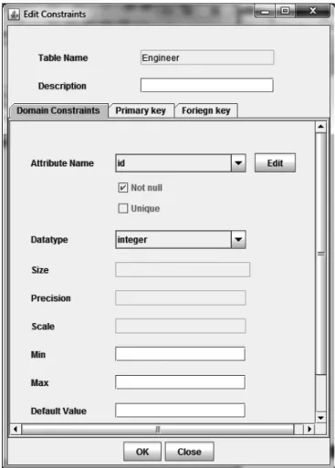
C. Editing Constraints
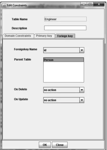
Database designers can specify domain constraint for each attribute as show in Fig. 4. Moreover, database designers can specify referential integrity constraint for each foreign key as show in Fig. 5.
Fig. 5. The screen of specify referential integrity constraint
D. Adding/Deleting Attribute
Database designers can add or delete attributes.
E. Generating Data Dictionary
This feature helps database designers generate data dictionary easily. This data dictionary can be saved in PDF format. The data dictionary consists of all relation names, attributes of the relations, data type of each attribute, primary keys, foreign keys, domain constraint, referential integrity constraint, and entity integrity constraint. An example of data dictionary is shown in Fig. 6.
Table Name: Engineering Attribute Name Data type Key Not null Unique Default Value Domain id integer PK, FK Not null name text PK, FK Not null idEngineer integer PK Not
null
Unique Foreign key Constraints
Foreign key name Reference table Column reference On delete On Update id Person id no action no action name Person name no action no action Column detail
Attribute Name Comment
id name idEngineer etype
Fig. 6. An example of data dictionary
F. Generating Database Schema
Database designers can create database schema in MySQL database and Oracle database automatically.
G. Generating SQL Script
This feature generates SQL script based on relation automatically. This script can be saved in text file.
VI. EMPIRICAL STUDIES
To test our tool, we use two software systems which are Institutional Key Performance Indicators Collecting System [7] and Order Food System.
A. Institutional Key Performance Indicators Collecting System
This system consists of regular entities, weak entities, 1: 1 binary relationship types, 1: N binary relationship types and M: N relationship types. The tool converts EER diagram, written in XML format into relation. The numbers of relation are 26 relations. Each relation has the primary key, attributes, and foreign keys. Table I shows relations of the system. After that, we specify relational database constraints for each relation. Then, we use this tool for generating SQL script. An example of script is shown in Fig. 7. This script includes relational database constraints according to user requirements. Finally, we execute this script with database. We found that this script generates relational database schema correctly.
create table Centers( id integer not null unique ,
center_name varchar(45) not null unique , primary key(id));
create table Departments( id integer not null unique , centers_id integer not null ,
department_name varchar(45) not null unique , primary key(id));
alter table Departments add foreign key (centers_id) references Centers(id) on delete restrict on update cascade;
Fig. 7. An example of SQL script for Institutional Key Performance Indicators Collecting System
TABLEI
RELATIONS OF INSTITUTIONAL KEY PERFORMANCE INDICATORS
COLLECTING SYSTEM Relation Name Number of
Attribute Number of Primary key Number of Foreign key Center 2 1 0 Department 3 1 1 KPI 11 1 5 Objective 2 1 0 Project 4 1 1
B. Order Food System
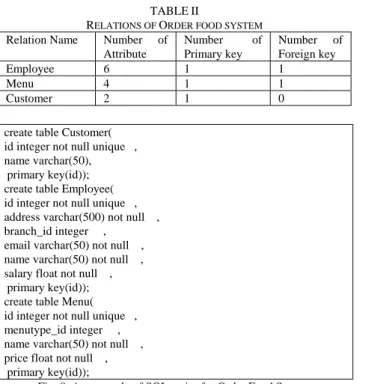
This system consists of regular entities, weak entities, superclasses, subclasses, 1:N relationship types, M: N relationship types, n-ary relationship type, specialization, and union. The tool converts EER diagram, written in XML format into relations. The numbers of relation are 24 relations. Each relation has the primary key, attributes, and foreign keys. Table II shows relations of the system. Then,
we use this tool generates SQL script. An example of script is shown in Fig. 8.
TABLEII
RELATIONS OF ORDER FOOD SYSTEM
Relation Name Number of Attribute Number of Primary key Number of Foreign key Employee 6 1 1 Menu 4 1 1 Customer 2 1 0
create table Customer( id integer not null unique , name varchar(50), primary key(id)); create table Employee( id integer not null unique , address varchar(500) not null , branch_id integer ,
email varchar(50) not null , name varchar(50) not null , salary float not null , primary key(id)); create table Menu( id integer not null unique , menutype_id integer , name varchar(50) not null , price float not null , primary key(id));
Fig. 8. An example of SQL script for Order Food System
VII. CONCLUSION
This paper presents a tool for generating relational database schema from EER diagram, written in XML format. The process of this tool receives EER diagram, written in XML format. Next, transforms it into relation. In this step, database designers can specify relational database constraints. Then the tool generates relational database schema. The results of this tool are relational database schema with constraints according to user requirements, database schema, and data dictionary. The advantages of this tool are database schema with constraints. In the future, we will develop this tool can generate test cases of relational database constraints. In addition, we will develop reverse engineering process for this tool. The tool will receive SQL script from database designers extract it into relation, attributes, and relationship.
REFERENCES
[1] P. Chen, "The Entity-Relationship Model: Toward a Unified a View of Data," ACM Transactions on Database Systems, vol. 1, pp. 9-36, 1976.
[2] R. Elmasri and S. B. Navathe, Fundamentals of Database Systems
(5th Edition). Boston, MA, USA: Addison-Wesley Longman
Publishing Co., Inc., 2006.
[3] S. Xu, Y. Li, and S. Lu, "ERDraw: An XML-Based ER Diagram Drawing and Translation Tool," 2003.
[4] S. Bagui and D. Walker, "A Java Based Parser Software for Converting XML Documents to the ER Model and Relational Databases," in SWWS, 2006, pp.166-169.
[5] P. Tongrak and T. Suwannasart, "A Tool for Generating Test Cases From Relational Database Constraints Testing," in Computer Science and Information Technology, 2009. ICCSIT 2009, 2nd IEEE International Conference on, Aug 2009, pp. 435-439.
[6] N. Sharma and et al., Database Fundamentals (1st Edition). Canada: IBM Corporation 2010.
[7] K. Tulayanisaka, "Institutional Key Performance Indicators Collecting System," Master's project, Department of Computer Engineering, Faculty of Engineering, Chulalongkorn University, 2009.
Lisa Simasatitkul received B.Sc. degree in Information Technology at the King Mongkut's Institute of Technology Ladkrabang in 2008. She is a master student in the Department of Computer Engineering, faculty of Computer Engineering at Chulalongkorn University. Her research interests are software engineering.
Taratip Suwannasart received Ph.D. degree in computer science at the Illinois Institute of Technology in 1996. She is working as an association professor in the Department of Computer Engineering, faculty of Computer Engineering at Chulalongkorn University. Her research interests are software engineering especially software testing and software quality assurance.